EP0178107B1 - Überziehen optischer Fasern - Google Patents
Überziehen optischer Fasern Download PDFInfo
- Publication number
- EP0178107B1 EP0178107B1 EP85306977A EP85306977A EP0178107B1 EP 0178107 B1 EP0178107 B1 EP 0178107B1 EP 85306977 A EP85306977 A EP 85306977A EP 85306977 A EP85306977 A EP 85306977A EP 0178107 B1 EP0178107 B1 EP 0178107B1
- Authority
- EP
- European Patent Office
- Prior art keywords
- fibre
- coating
- applicator
- frame
- concentricity
- Prior art date
- Legal status (The legal status is an assumption and is not a legal conclusion. Google has not performed a legal analysis and makes no representation as to the accuracy of the status listed.)
- Expired
Links
- 238000000576 coating method Methods 0.000 title claims abstract description 37
- 239000011248 coating agent Substances 0.000 title claims abstract description 36
- 230000003287 optical effect Effects 0.000 title description 2
- 239000000835 fiber Substances 0.000 claims abstract description 36
- 239000013307 optical fiber Substances 0.000 claims description 6
- 238000000034 method Methods 0.000 claims description 5
- 238000012544 monitoring process Methods 0.000 claims description 2
- 239000000463 material Substances 0.000 abstract description 2
- 239000003365 glass fiber Substances 0.000 description 5
- 230000008878 coupling Effects 0.000 description 2
- 238000010168 coupling process Methods 0.000 description 2
- 238000005859 coupling reaction Methods 0.000 description 2
- 239000011521 glass Substances 0.000 description 2
- 238000004519 manufacturing process Methods 0.000 description 2
- 230000003068 static effect Effects 0.000 description 2
- NIXOWILDQLNWCW-UHFFFAOYSA-M Acrylate Chemical compound [O-]C(=O)C=C NIXOWILDQLNWCW-UHFFFAOYSA-M 0.000 description 1
- JHWNWJKBPDFINM-UHFFFAOYSA-N Laurolactam Chemical compound O=C1CCCCCCCCCCCN1 JHWNWJKBPDFINM-UHFFFAOYSA-N 0.000 description 1
- 229920000299 Nylon 12 Polymers 0.000 description 1
- 239000012530 fluid Substances 0.000 description 1
- 239000000155 melt Substances 0.000 description 1
- 230000005499 meniscus Effects 0.000 description 1
- 239000011253 protective coating Substances 0.000 description 1
Images


Classifications
-
- B—PERFORMING OPERATIONS; TRANSPORTING
- B05—SPRAYING OR ATOMISING IN GENERAL; APPLYING FLUENT MATERIALS TO SURFACES, IN GENERAL
- B05C—APPARATUS FOR APPLYING FLUENT MATERIALS TO SURFACES, IN GENERAL
- B05C3/00—Apparatus in which the work is brought into contact with a bulk quantity of liquid or other fluent material
- B05C3/02—Apparatus in which the work is brought into contact with a bulk quantity of liquid or other fluent material the work being immersed in the liquid or other fluent material
- B05C3/12—Apparatus in which the work is brought into contact with a bulk quantity of liquid or other fluent material the work being immersed in the liquid or other fluent material for treating work of indefinite length
-
- C—CHEMISTRY; METALLURGY
- C03—GLASS; MINERAL OR SLAG WOOL
- C03C—CHEMICAL COMPOSITION OF GLASSES, GLAZES OR VITREOUS ENAMELS; SURFACE TREATMENT OF GLASS; SURFACE TREATMENT OF FIBRES OR FILAMENTS MADE FROM GLASS, MINERALS OR SLAGS; JOINING GLASS TO GLASS OR OTHER MATERIALS
- C03C25/00—Surface treatment of fibres or filaments made from glass, minerals or slags
- C03C25/10—Coating
- C03C25/12—General methods of coating; Devices therefor
- C03C25/18—Extrusion
Definitions
- This invention relates to the manufacture of optical fibres, particularly to coating a fibre.
- An optical fibre for telecommunications comprises a glass fibre drawn from a thicker glass rod (preform) in a high temperature furnace.
- the diameter of the fibre is measured by a monitor and interfaced with the speed at which the fibre is drawn in order to control the diameter of the fibre. It is also arranged to control movement of the preform chuck to maintain the position of the fibre-line below the furnace.
- Bare glass fibre has a strength which is easily degraded by the smallest of surface flaws. At least one durable protective coating is applied as soon as practical to the bare glass fibre to preserve the near flawless surface of a freshly drawn fibre. To give maximum protection any coating must be concentric about the fibre. A non-contacting concentricity monitor is used to monitor, and provide information to adjust the coating concentricity.
- fibre coatings are applied in a fluid state and under a degree of pressure onto the bare glass fibre as it passes through a coating applicator. Concentricity is adjusted by movement of the coating applicator about a static fibre-line.
- One method of adjustment is to translate the applicator in the horizontal plane (i. e. the plane perpendicular to the fibre-line). This method is found to be satisfactory when used with applicators with a « self-centering • coating capability, although drawbacks have been encountered.
- the response time to adjustments is long and a slight movement of the ideally static fibre-line results ; US patent 4321072 shows such an arrangement.
- a method of coating an optical fibre comprising drawing the fibre through a coating applicator having an entrance orifice and an exit orifice, and monitoring the concentricity of the coating on the fibre, characterised by tilting the applicator (6) about a pivot point (x, y) at or close to the lower exit orifice 10A to adjust and thereby maintain the desired concentricity of the coating (36) on the fibre (36').
- apparatus for coating an optical fibre comprising a coating applicator having an entrance orifice and an exit orifice through which the fibre passes, and means for mounting the applicator so both orifices are substantially concentric about the fibre-line, characterised by means (14, 15) for tilting the applicator (6) about a pivot point (x, y) at or close to the lower exit orifice (10A) in order to adjust and thereby maintain the desired concentricity of the coating (36) on the fibre (36').
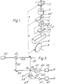
- a glass preform 1 is held in a preform chuck 2 which is adjustable in a horizontal plane to maintain the position of the fibre line below the furnace 3.
- the high temperature furnace 3 melts the preform and the glass fibre 4 is drawn by the fibre drawing wheel 9.
- the diameter of the fibre 4 is monitored by a fibre diameter monitor 5 which is interfaced electronically with the fibre drawing wheel 9 in order to control the fibre diameter.
- the monitor 5 also controls movement of the preform chuck 2 to maintain the fibre-line position below the furnace.
- the fibre enters a coating applicator 6 which is tiltably mounted to tilt about x and y axes under the control of a coating concentricity monitor 7 to maintain the coating, which may be Nylon 12 or acrylate, concentric with the fibre.
- a coating applicator 6 which is tiltably mounted to tilt about x and y axes under the control of a coating concentricity monitor 7 to maintain the coating, which may be Nylon 12 or acrylate, concentric with the fibre.
- the coating is cured in a curing stage 8.
- Concentricity adjustments are effected by guidance from the top orifice which restrains the fibre movement and situates it into the centre of the lower orifice. Response time has been found to be almost instantaneous. The fibre-line remains constant below the applicator during adjustments and so avoids complications connected with subsequent coating stages.
- Fig. 2 this has various cut-away lines X1 and X6 in Fig. 2B, and X2, X3, X4, X5 in Fig. 2A, for clarity.
- X4 (Fig. 2A) cuts away most of the near side wall of frame 11 to reveal frame 12
- X5 cuts away the near side wall of frame 12 to reveal chamber 10 and actuator 19.
- the applicator comprises a chamber 10 mounted on a first frame 12 which is pivotally mounted at Y on a second frame 11 to pivot about the y axis.
- Frame 11 in turn is pivotally mounted at X on a support frame 13 for pivotting the chamber 10 about the x axis.
- Pivot X is shown within the cut-away line X3 removing parts of the frames 11 and 13 for clarity in Fig. 2A.
- An electric actuator 14 is mounted at 14A on the frame 13 and is coupled at 14B to the frame.
- the coupling 14B is shown within the cut-away line X1 in Fig. 2B which has cut away the second Y pivot for clarity.
- Actuator 14 is the y-actuator for pivotting the chamber 10 and frame 12 about the y-axis.
- a second electric actuator 15 is mounted at 15A (Fig. 2B) on the support frame 13 and coupled at 15B to the second frame 11. This coupling 15B is shown within the cut-away line X2 which has cut away parts of the frame 11 and 13 for clarity in Fig. 2A.
- Actuator 15 is the x-actuator for pivotting the chamber 10, and frames 11 and 12, about the x-axis with respect to the support frame 13.
- the support frame 13 is mounted on a mounting bracket 16 in such a way that it can slide horizontally i. e. parallel to the x and y axis to shift the x-axis laterally and shift the y axes laterally so that the exit orifice 10A of the chamber 10 can be initially aligned with the fibre line as shown in Fig. 1.
- Linear actuators 17 and 18 are arranged to move the frame 13 to laterally shift the x and y axes, respectively, via slides 17A and 18A respectively.
- the linkeage mechanism 17B of one of the actuators (17) and which includes 45° DAVAL gears is shown within the cut away line X6 which cuts away part of the support frame 13 for clarity in Fig. 2B.
- the third linear actuator 19 is also provided to adjust the height of the applicator via a slide mounted on the frame 12.
- the height of the exit orifice of the chamber 10 can be adjusted so that it is level with the x and y tilt axes.
- the chamber 10 is mounted via a mount 10C on a wedge bracket 10D, in turn mounted on the slide of actuator 19.
- the concentricity monitor shown in Fig. 1 is shown in more detail in Fig. 3. It comprises essentially a light source 30, in this case a He-Ne laser, directed through a 50/50 beam splitter 31 which provides orthogonal beams 32 and 33 which are reflected through 90° by mirrors 34, 35 on to the fibre 36 which has just been coated.
- the coated fibre 36 produces scatter patterns 37, 38 which are symmetrical about central axes 39, 40 and displayed on transluscent screens 41, 42.
- the two light scatter patterns will be symmetrical in nature when the coating is concentric on the fibre, but become asymmetric for small coating eccentricities.
- the patterns are electronically detected by detector 43 and 44 which feed differential amplifiers 45, 46, whereby the asymetries are resolved and the necessary drive signals representative of the eccentricities are derived from respective power supplies 47, 48 to drive the motors of actuators 14 and 15 to adjust the tilts to maintain the desired concentricity.
- the coating chamber 10 can be as described in our co-pending British patent application 8403617 published 2153708 and this is shown schematically in Fig. 4 as a sectional view.
- the chamber contains the coating material IOE under pressure from port 10F and this rises to form a meniscus M just above the upper orifice 10B and around the approaching bare fibre 36'.
Landscapes
- Chemical & Material Sciences (AREA)
- Life Sciences & Earth Sciences (AREA)
- Geochemistry & Mineralogy (AREA)
- Engineering & Computer Science (AREA)
- Chemical Kinetics & Catalysis (AREA)
- General Chemical & Material Sciences (AREA)
- General Life Sciences & Earth Sciences (AREA)
- Materials Engineering (AREA)
- Organic Chemistry (AREA)
- Surface Treatment Of Glass Fibres Or Filaments (AREA)
- Optical Fibers, Optical Fiber Cores, And Optical Fiber Bundles (AREA)
- Coating Apparatus (AREA)
- Medicinal Preparation (AREA)
- Materials For Medical Uses (AREA)
- Application Of Or Painting With Fluid Materials (AREA)
Claims (5)
Priority Applications (1)
| Application Number | Priority Date | Filing Date | Title |
|---|---|---|---|
| AT85306977T ATE40877T1 (de) | 1984-10-10 | 1985-09-30 | Ueberziehen optischer fasern. |
Applications Claiming Priority (2)
| Application Number | Priority Date | Filing Date | Title |
|---|---|---|---|
| GB8425610 | 1984-10-10 | ||
| GB08425610A GB2165668B (en) | 1984-10-10 | 1984-10-10 | Coating optical fibres |
Publications (2)
| Publication Number | Publication Date |
|---|---|
| EP0178107A1 EP0178107A1 (de) | 1986-04-16 |
| EP0178107B1 true EP0178107B1 (de) | 1989-02-22 |
Family
ID=10567984
Family Applications (1)
| Application Number | Title | Priority Date | Filing Date |
|---|---|---|---|
| EP85306977A Expired EP0178107B1 (de) | 1984-10-10 | 1985-09-30 | Überziehen optischer Fasern |
Country Status (12)
| Country | Link |
|---|---|
| US (1) | US4631078A (de) |
| EP (1) | EP0178107B1 (de) |
| JP (1) | JPS6191047A (de) |
| CN (1) | CN1012571B (de) |
| AT (1) | ATE40877T1 (de) |
| AU (1) | AU571164B2 (de) |
| CA (1) | CA1226411A (de) |
| DE (1) | DE3568325D1 (de) |
| ES (1) | ES8705344A1 (de) |
| GB (1) | GB2165668B (de) |
| IN (1) | IN165280B (de) |
| ZA (1) | ZA857778B (de) |
Families Citing this family (11)
| Publication number | Priority date | Publication date | Assignee | Title |
|---|---|---|---|---|
| JPH0454191Y2 (de) * | 1987-10-29 | 1992-12-18 | ||
| EP0346723A1 (de) * | 1988-06-14 | 1989-12-20 | The Boeing Company | Verfahren und Vorrichtung zur Herstellung einer beschichteten optischen Faser mit besonderer Querschnittsform |
| US4899688A (en) * | 1988-11-14 | 1990-02-13 | E. I. Du Pont De Nemours And Company | Spin coating apparatus |
| JPH0791092B2 (ja) * | 1990-09-17 | 1995-10-04 | 住友電気工業株式会社 | 光フアイバ用樹脂塗布装置 |
| TW324788B (en) * | 1995-10-06 | 1998-01-11 | Sumitomo Electric Industries | Coating apparatuse for optical fiber |
| JPH10196341A (ja) | 1997-01-13 | 1998-07-28 | Nissan Motor Co Ltd | 内燃機関におけるオイルパンの制振構造 |
| US6520237B1 (en) * | 2000-07-24 | 2003-02-18 | Illinois Tool Works Inc | Variable spacing strand coating system and method |
| CN101005755B (zh) * | 2006-12-12 | 2011-04-20 | 中国乐凯胶片集团公司 | 一种电磁波屏蔽膜及其制造方法 |
| CN105271826B (zh) * | 2015-11-03 | 2018-11-23 | 江苏通鼎光棒有限公司 | 一种改善光纤筛选强度和涂覆同心度的装置及方法 |
| CN107056089A (zh) * | 2017-04-28 | 2017-08-18 | 成都中住光纤有限公司 | 一种光纤涂覆模座的在线调节系统 |
| CN106892556A (zh) * | 2017-04-28 | 2017-06-27 | 成都中住光纤有限公司 | 一种光纤拉丝夹头的在线调节系统 |
Family Cites Families (8)
| Publication number | Priority date | Publication date | Assignee | Title |
|---|---|---|---|---|
| US4042723A (en) * | 1976-05-12 | 1977-08-16 | Bell Telephone Laboratories, Incorporated | Method for monitoring the properties of plastic coatings on optical fibers |
| JPS54142320A (en) * | 1978-04-24 | 1979-11-06 | Fujitsu Ltd | Resin coated container for optical communication line |
| US4194462A (en) * | 1978-08-21 | 1980-03-25 | Corning Glass Works | Optical waveguide coating assembly |
| FR2469727A1 (fr) * | 1979-11-16 | 1981-05-22 | Thomson Csf | Procede de centrage automatique d'une fibre optique dans un revetement de protection primaire, et dispositif utilise pour la mise en oeuvre de ce procede |
| US4264649A (en) * | 1979-12-26 | 1981-04-28 | Corning Glass Works | Method for coating optical waveguide filaments |
| JPS57135740A (en) * | 1981-02-09 | 1982-08-21 | Showa Electric Wire & Cable Co Ltd | Resin coating apparatus of optical fiber |
| US4410344A (en) * | 1981-09-28 | 1983-10-18 | Western Electric Company, Inc. | Optical waveguide fiber draw guiding and coating method and apparatus |
| JPS5918130A (ja) * | 1982-07-21 | 1984-01-30 | Nippon Telegr & Teleph Corp <Ntt> | 光フアイバの被覆方法 |
-
1984
- 1984-10-10 GB GB08425610A patent/GB2165668B/en not_active Expired
-
1985
- 1985-09-30 EP EP85306977A patent/EP0178107B1/de not_active Expired
- 1985-09-30 DE DE8585306977T patent/DE3568325D1/de not_active Expired
- 1985-09-30 AT AT85306977T patent/ATE40877T1/de active
- 1985-10-02 US US06/782,930 patent/US4631078A/en not_active Expired - Lifetime
- 1985-10-03 IN IN810/DEL/85A patent/IN165280B/en unknown
- 1985-10-08 JP JP60222908A patent/JPS6191047A/ja not_active Withdrawn
- 1985-10-08 AU AU48392/85A patent/AU571164B2/en not_active Expired - Fee Related
- 1985-10-09 ZA ZA857778A patent/ZA857778B/xx unknown
- 1985-10-09 CA CA000492574A patent/CA1226411A/en not_active Expired
- 1985-10-09 CN CN85107960A patent/CN1012571B/zh not_active Expired
- 1985-10-10 ES ES547773A patent/ES8705344A1/es not_active Expired
Also Published As
| Publication number | Publication date |
|---|---|
| AU4839285A (en) | 1986-04-17 |
| AU571164B2 (en) | 1988-03-31 |
| ZA857778B (en) | 1986-06-25 |
| US4631078A (en) | 1986-12-23 |
| CA1226411A (en) | 1987-09-08 |
| GB2165668B (en) | 1988-03-02 |
| GB8425610D0 (en) | 1984-11-14 |
| EP0178107A1 (de) | 1986-04-16 |
| DE3568325D1 (en) | 1989-03-30 |
| GB2165668A (en) | 1986-04-16 |
| CN1012571B (zh) | 1991-05-08 |
| ES8705344A1 (es) | 1987-05-01 |
| ES547773A0 (es) | 1987-05-01 |
| ATE40877T1 (de) | 1989-03-15 |
| JPS6191047A (ja) | 1986-05-09 |
| CN85107960A (zh) | 1986-07-02 |
| IN165280B (de) | 1989-09-09 |
Similar Documents
| Publication | Publication Date | Title |
|---|---|---|
| EP0178107B1 (de) | Überziehen optischer Fasern | |
| US5226101A (en) | Method of laser polishing fiber optic connectors | |
| US9477042B2 (en) | Large diameter optical waveguide splice | |
| US5233200A (en) | Method and apparatus for contactless monitoring of tension in a moving fiber | |
| US5948134A (en) | Apparatus for forming a fiber optic coupler by dynamically adjusting pulling speed and heat intensity | |
| AU631834B2 (en) | An optical device | |
| CA1151876A (en) | Method for automatic centering of an optical fiber within a primary protective cladding and a device employed for carrying out said method | |
| KR100222347B1 (ko) | 광섬유 피복 방법 및 그 장치 | |
| CA2061516C (en) | Method of producing optical-fiber coupler | |
| CA2126726A1 (en) | Device and method for light beam splitting for dual sensor flame detector | |
| EP0091738B1 (de) | Präzises Einstellen optischer Fasern | |
| JP2866154B2 (ja) | 光ファイバーコーティングの制御 | |
| US4726677A (en) | Autofocused lightguide preform profiler | |
| US6588235B2 (en) | Method of centering a fiber core in a multiple-crucible method | |
| US6925839B2 (en) | Method for making capillary splice | |
| US6836370B2 (en) | Collimator for ready fitting to an optical device with precise optical alignment without need for adjusting positions or angles to compensate for offsets during assembly | |
| US6854293B2 (en) | Method for fusion splicing of optical fibers | |
| US6735360B2 (en) | Apparatus of making collimators for precise alignment of optical paths without need for adjusting positions or angles to compensate for offsets or deviations during optical device assembly | |
| US20020136490A1 (en) | MEMS optical switch including tapered fiber with hemispheric lens | |
| WO2002083585A1 (en) | Filament housing for fiber splicing and lens fabrication processes | |
| JPH04149503A (ja) | 光ファイバカプラの製造用延伸台 | |
| JPH03154009A (ja) | 光フアイバカプラの製造装置 | |
| JPH09243847A (ja) | フィルタ挿入型光導波路の製造方法及び製造装置 |
Legal Events
| Date | Code | Title | Description |
|---|---|---|---|
| PUAI | Public reference made under article 153(3) epc to a published international application that has entered the european phase |
Free format text: ORIGINAL CODE: 0009012 |
|
| AK | Designated contracting states |
Kind code of ref document: A1 Designated state(s): AT BE CH DE FR GB IT LI LU NL SE |
|
| 17P | Request for examination filed |
Effective date: 19860617 |
|
| 17Q | First examination report despatched |
Effective date: 19870622 |
|
| GRAA | (expected) grant |
Free format text: ORIGINAL CODE: 0009210 |
|
| AK | Designated contracting states |
Kind code of ref document: B1 Designated state(s): AT BE CH DE FR GB IT LI LU NL SE |
|
| PG25 | Lapsed in a contracting state [announced via postgrant information from national office to epo] |
Ref country code: SE Effective date: 19890222 Ref country code: NL Effective date: 19890222 Ref country code: LI Effective date: 19890222 Ref country code: IT Free format text: LAPSE BECAUSE OF FAILURE TO SUBMIT A TRANSLATION OF THE DESCRIPTION OR TO PAY THE FEE WITHIN THE PRESCRIBED TIME-LIMIT;WARNING: LAPSES OF ITALIAN PATENTS WITH EFFECTIVE DATE BEFORE 2007 MAY HAVE OCCURRED AT ANY TIME BEFORE 2007. THE CORRECT EFFECTIVE DATE MAY BE DIFFERENT FROM THE ONE RECORDED. Effective date: 19890222 Ref country code: CH Effective date: 19890222 Ref country code: BE Effective date: 19890222 Ref country code: AT Effective date: 19890222 |
|
| REF | Corresponds to: |
Ref document number: 40877 Country of ref document: AT Date of ref document: 19890315 Kind code of ref document: T |
|
| REF | Corresponds to: |
Ref document number: 3568325 Country of ref document: DE Date of ref document: 19890330 |
|
| ET | Fr: translation filed | ||
| REG | Reference to a national code |
Ref country code: CH Ref legal event code: PL |
|
| NLV1 | Nl: lapsed or annulled due to failure to fulfill the requirements of art. 29p and 29m of the patents act | ||
| PG25 | Lapsed in a contracting state [announced via postgrant information from national office to epo] |
Ref country code: LU Free format text: LAPSE BECAUSE OF NON-PAYMENT OF DUE FEES Effective date: 19890930 |
|
| RAP2 | Party data changed (patent owner data changed or rights of a patent transferred) |
Owner name: STC PLC |
|
| PLBE | No opposition filed within time limit |
Free format text: ORIGINAL CODE: 0009261 |
|
| STAA | Information on the status of an ep patent application or granted ep patent |
Free format text: STATUS: NO OPPOSITION FILED WITHIN TIME LIMIT |
|
| 26N | No opposition filed | ||
| REG | Reference to a national code |
Ref country code: FR Ref legal event code: EM |
|
| REG | Reference to a national code |
Ref country code: GB Ref legal event code: 732E |
|
| REG | Reference to a national code |
Ref country code: FR Ref legal event code: TP |
|
| PGFP | Annual fee paid to national office [announced via postgrant information from national office to epo] |
Ref country code: FR Payment date: 20010813 Year of fee payment: 17 |
|
| REG | Reference to a national code |
Ref country code: GB Ref legal event code: IF02 |
|
| PG25 | Lapsed in a contracting state [announced via postgrant information from national office to epo] |
Ref country code: FR Free format text: LAPSE BECAUSE OF NON-PAYMENT OF DUE FEES Effective date: 20030603 |
|
| REG | Reference to a national code |
Ref country code: GB Ref legal event code: 732E |
|
| REG | Reference to a national code |
Ref country code: FR Ref legal event code: ST |
|
| REG | Reference to a national code |
Ref country code: GB Ref legal event code: 732E |
|
| PGFP | Annual fee paid to national office [announced via postgrant information from national office to epo] |
Ref country code: GB Payment date: 20030924 Year of fee payment: 19 |
|
| PGFP | Annual fee paid to national office [announced via postgrant information from national office to epo] |
Ref country code: DE Payment date: 20031009 Year of fee payment: 19 |
|
| PG25 | Lapsed in a contracting state [announced via postgrant information from national office to epo] |
Ref country code: GB Free format text: LAPSE BECAUSE OF NON-PAYMENT OF DUE FEES Effective date: 20040930 |
|
| PG25 | Lapsed in a contracting state [announced via postgrant information from national office to epo] |
Ref country code: DE Free format text: LAPSE BECAUSE OF NON-PAYMENT OF DUE FEES Effective date: 20050401 |
|
| GBPC | Gb: european patent ceased through non-payment of renewal fee |
Effective date: 20040930 |