EP0178276A2 - Motorantrieb/Steuerstromkreis - Google Patents
Motorantrieb/Steuerstromkreis Download PDFInfo
- Publication number
- EP0178276A2 EP0178276A2 EP85850313A EP85850313A EP0178276A2 EP 0178276 A2 EP0178276 A2 EP 0178276A2 EP 85850313 A EP85850313 A EP 85850313A EP 85850313 A EP85850313 A EP 85850313A EP 0178276 A2 EP0178276 A2 EP 0178276A2
- Authority
- EP
- European Patent Office
- Prior art keywords
- winding
- motor
- current
- control circuit
- drive
- Prior art date
- Legal status (The legal status is an assumption and is not a legal conclusion. Google has not performed a legal analysis and makes no representation as to the accuracy of the status listed.)
- Withdrawn
Links
Images

Classifications
-
- H—ELECTRICITY
- H02—GENERATION; CONVERSION OR DISTRIBUTION OF ELECTRIC POWER
- H02P—CONTROL OR REGULATION OF ELECTRIC MOTORS, ELECTRIC GENERATORS OR DYNAMO-ELECTRIC CONVERTERS; CONTROLLING TRANSFORMERS, REACTORS OR CHOKE COILS
- H02P8/00—Arrangements for controlling dynamo-electric motors rotating step by step
- H02P8/12—Control or stabilisation of current
Definitions
- the present invention relates to an energy controlling circuit used in connection with a motor and, in particular, to a stepping motor drive/control circuit for minimizing energy losses in the stepping motor.
- the drive/ control circuit of the present invention was created to permit the transfer or delivery of energy remaining in a winding to another winding in a bifilar stepping motor and thereby minimize energy dissipation in the motor.
- the circuit of the present invention also resulted in a substantial reduction in the weight of the electrical and mechanical stepping motor assembly.
- a large, heavy transformer is used in supplying power to the stepping motor.
- the drive/control circuit disclosed herein does not require such a transformer but relies on the circuit itself to provide the necessary voltage level, and concomitantly the necessary current to the motor windings. As a result, the weight of the stepping motor system is significantly minimized because a heavy transformer is not used.
- a stepping motor drive/control circuit in which energy is transferred from a previously excited motor winding to a subsequently excited motor winding to minimize energy dissipation in the motor and thereby maximize the power efficiency of the motor.
- the drive/ control circuit includes a common inductor or choke which is electrically connected at both of its ends or sides to both windings of a bifilar stepping motor.
- a first side of the common inductor is connected to each of the two motor windings through a catch diode.
- the second side of the common inductor is connected to each of the center taps of the two motor windings.
- the motor windings are electrically connected to a number of controlled switch means or units.
- each comprises two coils.
- four switch units are provided, one of the four coils being electrically connected to one of the four switch units.
- the switch units are operably connected to a controller which controls the opening and the closing of the switch units in a predetermined manner.
- the manner of opening and closing the switch units is intended to generate a sinusoid-shaped motor current. This current is detected using a sensing resistor which communicates with a controller.
- the controller opens and closes the switch units based on the current sensed.
- a primary current is generated which passes through the first motor winding due to the collapsing magnetic field associated therewith.
- the primary current passes through the catch diode in electrical communication with the first winding, and which catch diode is now forward biased by the back emf of the common inductor and the previously energized coil.
- the primary current also passes through the common inductor.
- a secondary current path is created in the opposite direction through the first winding to the second winding, which enables the energy of the first winding to be transferred to the second winding.
- This path for secondary current also includes the same catch diode, with the current of the secondary path being less in magnitude than the current through the primary path so that the resulting current through the catch diode is in the direction from the anode to the cathode of the catch diode.
- a stepping motor drive/control circuit which makes use of energy present in a previously excited motor winding by transferring such existing energy to another winding of the motor. Such a transfer of energy improves the efficiency of the motor since less energy is required from the supplied power to properly energize a motor winding coil.
- a common inductor is used that results in the further advantage of reducing the weight of the motor assembly in that a heavy transformer is not required to receive the line voltage which provides power to the motor.
- the common inductor of the inventive circuit enables a large, rectified supply voltage to be applied to the circuit so that a sufficiently large current is generated in the motor windings.
- a drive/ control circuit for use with a stepping motor having at least two windings.
- the present invention is characterized by the transfer of energy from a previously excited motor winding to a subsequently excited motor winding.
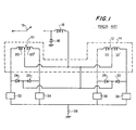
- FIG. 1 illustrates a prior art conventional drive circuit connected to two windings 10, 12 of a bifilar stepping motor 14.
- the supply voltage V is applied to a control switch 15 and rectified by a diode 16 and applied to a choke or inductor 18 whenever the control switch 15 is closed. Both the diode 16 and the inductor 18 are provided on the input or upstream side of the stepping motor 14.
- the windings 10, 12 include the coils 20, 20', and 22, 22', respectively, each of these coils being defined using the center tap of the windings 10, 12.
- One side of the inductor 18 is electrically connected to the center tap of each of the two windings 10, 12.
- the drive control circuit of the prior art system includes four catch diodes 24, 26, 28, 30, each of which is used to prevent a direct current path from the inductor 18 to one of the switches 32, 34, 36, 38, one of which is normally closed during use of the stepping motor 14.
- the catch diodes 24-30 are also used to prevent the formation of a current path to a motor winding coil other than the desired winding coil which is to be energized.
- Each of the catch diodes 24-30 is electrically connected to the downstream side of the inductor 18.
- the prior art circuit also includes a sensing resistor 39 electrically connected to the switches 32-38.
- the prior art circuit of Fig. 1 outputs a current to the sensing resistor 39 in a manner controlled by the control switch 15.
- a current having a pulse waveform is generated in the motor windings 10, 12.
- the frequency of the pulse waveform corresponds to the frequency of the opening/closing of the control switch 15.
- more than one switch 32-38 is closed at any instance in time.
- swtiches 32, 36 are closed simultaneously so that greater power is generated by the motor 14.
- the prior art circuit of Fig. 1 does not transfer energy or current from a first winding to a second winding of the bifilar stepping motor.
- the current present in the winding 10 is dissipated in the winding 10.
- the prior art circuit and the operation thereof do not result in the efficient use of the energy produced in the windings 10, 12. Additionally, because the prior art circuit relies on a pulse current waveform being generated, the stepping motor shaft moves in discrete steps. As the following discussion indicates, the present invention generates a sinusoidal current signal so that a relatively smooth motor shaft movement occurs.
- the present invention provides an apparatus for transferring the previously generated energy in a motor winding using, in a preferred embodiment, the combination of elements illustrated in Fig. 2.
- a bifilar stepping motor 40 is shown having a pair of windings 42, 44.
- the winding 42 comprises coils 46, 46' while winding 44 comprises coils 48, 48'.
- Coils 46, 46' are defined using a center tap electrically connected to a first or downstream side of a common inductor 50.
- the coils 48, 48' are also defined using a center tap electrically connected to the same first side of the common inductor 50.
- the common inductor 50 forms a part of the stepping motor drive/control circuit 52.
- the circuit 52 further includes catch diodes 54, 56, 58, 60, switch units 62, 64, 66, 68, a controller 70, and current sensing resistor 72.
- Each of the catch diodes 54-60 is electrically connected between a second or upstream side of the common inductor 50 and one of the coils 46, 46', 48, 48'.
- Each of the switch units 62-68 is electrically responsive to and in communication with one of the coils 46, 46', 48, 48'.
- each of the switch units 62-68 includes a Darlington transistor and a built in catch diode for circuit protection.
- the controller 70 is electrically connected to the switch units 62-68 and controls the opening and closing thereof.
- the controller 70 acts to close only one of the four switch units 62-68 at any one time, and the rate of closing one switch unit and opening a second switch unit is about 19.2 KHz.
- the stepping motor 40 acts like an AC synchronous motor.
- a sinusoidal current waveform is generated in the stepping motor 40 which results in a smooth movement of the motor shaft.
- the opening/closing of the switch units 62-68 is at a faster rate than the frequency of the sinusoidal current generated by the stepping motor 40.
- the sinusoidal current is basically made up of a number of average currents present in the winding coils. Each average current is essentially an average magnitude of current present in the winding coil during the time one of the switch units 62-68 was closed.
- the frequency of the opening/closing of the switch units 62-68 is relatively fast so that the change in current in the winding coil due to the opening of a switch unit 62-68 is very small in comparison with the average current present in the coil during the opening/closing sequence.
- the controller 70 is able to generate the desired, both in amplitude and frequency, sinusoidal current waveform for producing a desired motor shaft rotation.
- one period of the generated sinusoidal current results in a 7.2 degree movement of the motor shaft.
- the frequency of the sinsuoidal current signal increases, the rotational movement of the motor shaft increases also.
- the common inductor 50 and the catch diodes 54-66 in conjunction with the opening and closing of the switch units 62-68, cause current to be removed from one winding 42, 44 and transferred to the other of the two windings 42 or 44.
- current is not transferred most efficiently because the current in the stepping motor 40 is not constant due to the decay of the current over time between the opening of one switch unit 62-68 and the closing of another switch unit 62-68. Additionally, the inductance of the conductor 50 cannot be infinite.
- FIG. 3 shows a portion of the schematic representation of Fig. 2 in order to illustrate the current paths that result upon opening of the switch unit 62 and the subsequent closing of the switch unit 66.
- coil 46 of the winding 42 is energized and current has a path from the rectified line voltage through the common inductor 50, the coil 46, the switch unit 62, and the sensing resistor 72.
- the current energizes or excites the coil 46 for use in causing a desired movement of the shaft of the stepping motor 40.
- the switch unit 62 is opened and then the switch unit 66 is closed.
- the winding 46 acts, at least to a first approximation, like a constant current source in that the amount of current passing through the coil 46 remains substantially the same as that passing therethrough when the switch unit 62 was closed.
- a primary current path for this current is through a path including the diode 54 and the common inductor 50. This current path results because the diode 54 is forward biased with the opening of the switch unit 62.
- a secondary current is also developed through the coil 46 of the winding 42, but in the opposite direction of the primary current. That is, with the closing of the switch unit 66, a current path is provided from the rectified line voltage V through the diode 54, the winding coil 46, the winding coil 48, the switch unit 66, and the sensing resistor 72. A portion of the secondary current takes this current path while the remaining portion of the secondary current passes from the winding coil 46 to the common inductor 50.
- the magnitude of the primary current through the winding coil 46 is greater in magnitude than the secondary current through the winding coil 46 in the opposite direction.
- the secondary current is in a direction from the cathode to the anode of the diode 54
- the resulting current through the diode 54 is from anode to cathode.
- the transfer of energy from one of the motor windings 42, 44, in this example, from the winding 42, to another of the motor windings, namely winding 44, is in the form of that portion of the secondary current passing to the winding coil 48.
- This transfer of current reduces the amount of current required to be generated by the line voltage through the common inductor 50 when the switch unit 66 is closed. As a result, the dissipation of energy in the winding 42 and the common inductor 50 is minimized, and the efficiency of the stepping motor 40 is increased.
- the inductance of the common inductor 50 is 2-5 times as great in magnitude as the inductance of each of the winding coils 46,46',48, 48'. In arriving at this preferred range, greater transfer of energy occurs from a previously excited winding to a subsequently excited winding when the inductance of the common inductor 50 is relatively much greater than the inductance of the winding coils 46,46', 48,48'. This result occurs essentially because the common inductor 50 and the subsequently excited winding coil, in the present example winding coil 48, are electrically in parallel.
- the magnitude of the secondary current through the subsequently excited winding coil becomes greater as the magnitude of the inductance of the common inductor 50 is increased relative to the inductance of the subsequently excited winding coil.
- the magnitude of the inductance of the common inductor 50 cannot be made too great, otherwise the current rise time through the common inductor is too large and the response time of the stepping motor 40 becomes unacceptable.
- the present invention also minimizes energy losses at greater stepping rates of switch unit closures, unlike prior art drive or control circuits. At greater stepping rates with the accompanying change in the direction of magnetism, greater energy losses result in the conventional stepping motor. This energy is therefore not properly utilized. Such energy losses do not occur in the present invention because of the use of the common inductor 50 having a relatively large inductance. The inductor 50 effectively and efficiently handles the high frequency current due to the high switching rates so that magnetic losses resulting from the switching are less than prior art circuits.
- the magnetic position of the motor is different from the expected, actual position of the motor shaft due to the fact that at any instance in time the current may be different than that current required to effect a desired motor shaft movement.
- the motor shaft is unable to move rapidly enough in response to such current. Instead, the motor shaft reacts to an average current. As an end result, significant accuracy is still achieved with respect to obtaining a desired motor shaft position.
- the common inductor 50 permits the application of a relatively large rectified supply voltage to the stepping motor 40 without possible damage to the motor windings 42, 44. This occurs because a substantial portion of the rectified supply voltage remains across the common inductor 50 having a relatively large inductance.
- the common inductor 50 eliminates the need for a heavy transformer on the input side to the stepping motor 40. In so doing, the weight of the motor is appreciably reduced.
- switch unit 62-68 With respect to the opening and closing of the switch units 62-68, although more than one switch unit 62-68 may be closed at any one time, in the preferred operation only one switch unit 62-68 is closed at a given time and, therefore, only one sensing resistor 72 need be utilized because current is passing only through one switch unit 62-68 at a time. Accordingly, because only switch unit 62-68 is closed at one time, the amount of current transferred to the subsequently excited winding coil is maximized since the amount of current from the previously excited winding through the common inductor 50 is minimized.
- the present invention is able to utilize previously generated energy in a subsequently excited motor winding.
- the circuit of the present invention and the operation thereof thereby increases the power efficiency of the stepping motor.
- An inductor common to both windings of the bifilar stepping motor is important in providing the desired transfer of current in the preferred embodiment. Additionally, because the common inductor is able to provide the same functions as a heavy transformer, the weight of the motor assembly is reduced as the rectified line voltage can be applied directly to the common inductor. Furthermore, high frequency current generated as a result of the relatively fast opening and closing of switches is properly handled by the large inductance of the common inductor and energy losses in the stepping motor are thereby reduced.
Landscapes
- Engineering & Computer Science (AREA)
- Power Engineering (AREA)
- Control Of Stepping Motors (AREA)
- Dc Machiner (AREA)
Applications Claiming Priority (2)
| Application Number | Priority Date | Filing Date | Title |
|---|---|---|---|
| US65877584A | 1984-10-09 | 1984-10-09 | |
| US658775 | 1984-10-09 |
Publications (2)
| Publication Number | Publication Date |
|---|---|
| EP0178276A2 true EP0178276A2 (de) | 1986-04-16 |
| EP0178276A3 EP0178276A3 (de) | 1987-07-01 |
Family
ID=24642643
Family Applications (1)
| Application Number | Title | Priority Date | Filing Date |
|---|---|---|---|
| EP85850313A Withdrawn EP0178276A3 (de) | 1984-10-09 | 1985-10-07 | Motorantrieb/Steuerstromkreis |
Country Status (3)
| Country | Link |
|---|---|
| EP (1) | EP0178276A3 (de) |
| JP (1) | JPS61167400A (de) |
| ES (1) | ES8703693A1 (de) |
Cited By (3)
| Publication number | Priority date | Publication date | Assignee | Title |
|---|---|---|---|---|
| CN113826179A (zh) * | 2019-05-15 | 2021-12-21 | 赖茵豪森机械制造公司 | 用于执行运行设备的至少一个切换设备的切换的方法以及用于运行设备的至少一个切换设备的驱动系统 |
| US20220277906A1 (en) * | 2019-05-15 | 2022-09-01 | Maschinenfabrik Reinhausen Gmbh | Method for carrying out a switchover of at least two switching means for equipment, and drive system for at least two switching means in equipment |
| CN113826179B (zh) * | 2019-05-15 | 2026-05-08 | 赖茵豪森机械制造公司 | 用于执行运行设备的至少一个切换设备的切换的方法以及用于运行设备的至少一个切换设备的驱动系统 |
Family Cites Families (2)
| Publication number | Priority date | Publication date | Assignee | Title |
|---|---|---|---|---|
| US3444447A (en) * | 1966-09-22 | 1969-05-13 | Mesur Matic Electronics Corp | Multi-phase step motor control circuits including means for supplementing the normal energization of the windings |
| US4468601A (en) * | 1982-07-02 | 1984-08-28 | The Perkin-Elmer Corporation | Stepper motor control |
-
1985
- 1985-10-07 EP EP85850313A patent/EP0178276A3/de not_active Withdrawn
- 1985-10-08 ES ES547667A patent/ES8703693A1/es not_active Expired
- 1985-10-09 JP JP22388985A patent/JPS61167400A/ja active Pending
Cited By (5)
| Publication number | Priority date | Publication date | Assignee | Title |
|---|---|---|---|---|
| CN113826179A (zh) * | 2019-05-15 | 2021-12-21 | 赖茵豪森机械制造公司 | 用于执行运行设备的至少一个切换设备的切换的方法以及用于运行设备的至少一个切换设备的驱动系统 |
| US20220223357A1 (en) * | 2019-05-15 | 2022-07-14 | Maschinenfabrik Reinhausen Gmbh | Method for carrying out a switchover of at least one switching means for equipment, and drive system for at least one switching means for equipment |
| US20220277906A1 (en) * | 2019-05-15 | 2022-09-01 | Maschinenfabrik Reinhausen Gmbh | Method for carrying out a switchover of at least two switching means for equipment, and drive system for at least two switching means in equipment |
| US11948761B2 (en) * | 2019-05-15 | 2024-04-02 | Maschinenfabrik Reinhausen Gmbh | Method for carrying out a switchover of at least two switching means for equipment, and drive system for at least two switching means in equipment |
| CN113826179B (zh) * | 2019-05-15 | 2026-05-08 | 赖茵豪森机械制造公司 | 用于执行运行设备的至少一个切换设备的切换的方法以及用于运行设备的至少一个切换设备的驱动系统 |
Also Published As
| Publication number | Publication date |
|---|---|
| EP0178276A3 (de) | 1987-07-01 |
| ES8703693A1 (es) | 1987-02-16 |
| ES547667A0 (es) | 1987-02-16 |
| JPS61167400A (ja) | 1986-07-29 |
Similar Documents
| Publication | Publication Date | Title |
|---|---|---|
| AU673178B2 (en) | Variable reluctance drive system | |
| EP0506408B1 (de) | Steuerschaltung mit Energierückgewinnung für einen Reluktanzmotor | |
| AU619096B2 (en) | Current chopping strategy for switched reluctance machines | |
| EP0802623B1 (de) | Umrichterschaltung für geschaltete mehrphasige induktive Last | |
| US5686805A (en) | Repulsion motor | |
| US4607322A (en) | Energy recovery snubber | |
| EP0178615A2 (de) | Stromversorgungssysteme für induktive Elemente | |
| US5070292A (en) | Pulse-width modulated circuit for driving a load | |
| EP0739078A3 (de) | Elektromagnetische Rotationsmaschine | |
| US4295083A (en) | Pulsed energy stepping motor power control unit | |
| GB2273212A (en) | Converter for switched reluctance motor | |
| US5764019A (en) | Control circuit and system for a switched reluctance machine and method of operating | |
| JP4302470B2 (ja) | スイッチトリラクタンス機械とともに用いられる回路 | |
| KR100632805B1 (ko) | 고주파 교류 발전기 자계의 공진 여진을 위한 장치 | |
| US4908563A (en) | Method and device for braking a squirrel-cage motor | |
| EP0178276A2 (de) | Motorantrieb/Steuerstromkreis | |
| JPH0970172A (ja) | 電気調整器 | |
| US4709314A (en) | Superconducting rectifier for the conversion of a relatively low alternating current into a relatively high direct current | |
| RU2099850C1 (ru) | Способ управления асинхронным двигателем с фазным ротором | |
| US5221885A (en) | Low-power dual voltage drive circuit and method | |
| US4418309A (en) | Two phase induction motor circuit with series connected center-tapped stator windings | |
| US4017786A (en) | Transformer saturation control circuit for a high frequency switching power supply | |
| CA1124319A (en) | Chopping power supply for a bifilar stepping motor | |
| EP0138301B1 (de) | Hochspannungsschaltnetzteil | |
| JPH09182492A (ja) | Igbtパワー・トランジスタ用の絶縁ゲート駆動部を持つコンパクトな高効率電子モータ・コントローラおよびその分散型電源 |
Legal Events
| Date | Code | Title | Description |
|---|---|---|---|
| PUAI | Public reference made under article 153(3) epc to a published international application that has entered the european phase |
Free format text: ORIGINAL CODE: 0009012 |
|
| AK | Designated contracting states |
Kind code of ref document: A2 Designated state(s): AT DE FR GB IT SE |
|
| PUAL | Search report despatched |
Free format text: ORIGINAL CODE: 0009013 |
|
| AK | Designated contracting states |
Kind code of ref document: A3 Designated state(s): AT DE FR GB IT SE |
|
| STAA | Information on the status of an ep patent application or granted ep patent |
Free format text: STATUS: THE APPLICATION HAS BEEN WITHDRAWN |
|
| 18W | Application withdrawn |
Withdrawal date: 19870919 |
|
| RIN1 | Information on inventor provided before grant (corrected) |
Inventor name: FELLINGER, MICHAEL W. |