EP0178543A2 - Verfahren zum Kontrollieren der Form einer durch einen Erodierdraht bearbeiteten Oberfläche und Vorrichtung zur Durchführung dieses Verfahrens - Google Patents
Verfahren zum Kontrollieren der Form einer durch einen Erodierdraht bearbeiteten Oberfläche und Vorrichtung zur Durchführung dieses Verfahrens Download PDFInfo
- Publication number
- EP0178543A2 EP0178543A2 EP85112517A EP85112517A EP0178543A2 EP 0178543 A2 EP0178543 A2 EP 0178543A2 EP 85112517 A EP85112517 A EP 85112517A EP 85112517 A EP85112517 A EP 85112517A EP 0178543 A2 EP0178543 A2 EP 0178543A2
- Authority
- EP
- European Patent Office
- Prior art keywords
- wire
- discharges
- numbers
- counting
- circuit
- Prior art date
- Legal status (The legal status is an assumption and is not a legal conclusion. Google has not performed a legal analysis and makes no representation as to the accuracy of the status listed.)
- Granted
Links
Images

Classifications
-
- B—PERFORMING OPERATIONS; TRANSPORTING
- B23—MACHINE TOOLS; METAL-WORKING NOT OTHERWISE PROVIDED FOR
- B23H—WORKING OF METAL BY THE ACTION OF A HIGH CONCENTRATION OF ELECTRIC CURRENT ON A WORKPIECE USING AN ELECTRODE WHICH TAKES THE PLACE OF A TOOL; SUCH WORKING COMBINED WITH OTHER FORMS OF WORKING OF METAL
- B23H7/00—Processes or apparatus applicable to both electrical discharge machining and electrochemical machining
- B23H7/02—Wire-cutting
- B23H7/04—Apparatus for supplying current to working gap; Electric circuits specially adapted therefor
Definitions
- Known methods for detecting machining faults during cutting by electroerosion of a part by means of a wire consist in measuring the deviation of the wire relative to a straight line joining its guides, either by a direct measurement of this deviation between the part and one of the guides, ie from the relative movements of the guides of the wire with respect to the part. This deflection of the wire causes a cutting error or a bending of the machined surface of the part in the case of a finishing phase.
- machining faults can also appear on the machined surface even if the wire is straight between its guides.
- One of the causes of these faults is the uneven state of pollution of the dielectric along the machining zone, the effect of which is to vary the spark distance between the wire and the part. along the same lines as pollution.
- These faults can also be due to deposits of material on the part at certain points in the machining area.
- the invention aims to detect faults machining in question. To this end, the invention is defined as stated in claim 1.
- a weight can be assigned to each discharge during counting, depending on the machining current consumed during this discharge.
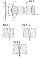
- FIG. 1 illustrates a simple case, where the cutting wire 1 stretched between the guides 2 moved from A to B when cutting a piece 3 of thickness H.
- the movement of the wire in advance relative to to part 3, as well as the various attractive and repulsive forces acting on the wire during sparking make that once arrived at B, the wire (then designated by the) instead of being straight between its guides ( designated at this time by 2 ') will have a curvature that drags behind the right joining the guides, which will result in a defect of usi swims if the cutting path in a plane normal to this right describes a marked curve at this point.
- the Z axis represents a coordinate parallel to the right joining the guides 2 and the Y axis a coordinate along which is reported the number N 1 of discharges detected in each of the eight sectors from the start of machining. If it is assumed for simplicity that the value of the machining current - and therefore the amount of eroded material - has remained the same for all discharges, then the amount of material removed in each sector S i will be proportional to the number N i of discharges carried out in this sector.
- each of these numbers Ni and a reference value which in the simplest case may be the average N of all N 1 , make it possible to determine the form that the wire takes in B, if the counting is carried out at from a moment the wire is straight, eg when it is at A. If we know that the slot created by the wire is often flared in its upper part - as shown in fig. 2 - we can eg multiply the numbers N i corresponding to the upper part of the slit by appropriate factors (less than 1) to obtain corrected numbers N i 'essentially proportional to the working distance traveled by the wire in the slices Si since the beginning of the count. Alternatively, it is naturally possible to adjust not the numbers N i but the reference numbers R i to which they are compared to detect a machining defect.
- the block diagram of fig. 5, which shows a wire cutting installation comprising a circuit for detecting geometric machining faults will now be briefly described.
- Part 3 is cut by the wire 1 stretched over guides 2.
- Two motors 11 & 12 control the movements of the workpiece parallel to the cutting plane, and two other motors 13 and 14 control the movements of a guide 2 relative to each other and therefore the orientation of the wire relative to the workpiece.
- the installation comprises a pulse generator circuit which comprises a voltage source 15 in series with a switch 16 controlled by an oscillator.
- Circuit 21 calculates the ratio of the difference between the currents flowing in the two supply lines of the wire and the sum of these currents. This difference (il - i 2 ) is measured by a conductor shunting these two branches; the quotient obtained is compared with values representative of each sector of the wire, and the circuit 21 emits a logic signal as soon as the value of the quotient corresponds to one of these branches.
- a discriminator circuit 17 of known type emits a logic signal as soon as an erosive discharge appears, thus eliminating the effect of possible discharges without erosive action, such as short circuits which inevitably appear under certain conditions. We know that these are characterized by high currents, but with very low voltage drops compared to the usual spark voltages. This results in weak localized heating without removal of material. This is why the discrimination circuit 17 must be able to recognize a short circuit and not to emit a logic signal in such a case. If it is envisaged to classify the erosive discharges according to their intensity, in order to weight their influence during the counting, the circuit 17 could if necessary be used to carry out this weighting.
- the signal ; output from circuit 17 controls AND gate 10 to pass a signal through each erosive discharge counter corresponding to the part of the wire where this discharge occurred.
- the counters necessary for this recording are included in a sector counting unit 22 which also receives the signals emitted by a clock 25.
- the values of the numbers of discharges per unit of time in the different parts, or sectors, of the wire are transmitted from the counting unit 22 to a data processing unit 23 which can either contain predetermined set values for the numbers of discharges per unit of time, or calculate set values from the information it receives from the the counting unit 22.
- the data processing unit 23 further performs the comparisons necessary to determine whether the differences between the values of the number of effective discharges and the set values exceed a predetermined level.
- comparisons can take into account signals characterizing the relative displacements of the wire and the part, these signals being delivered to the data processing circuit 23 by a digital control circuit 24 which controls the motors 11 to 14.
- the control circuit 24 itself receives signals transmitted by a speed regulator 26 adjusting the gap by modifying the speed of advance of the wire as a function of the difference between the effective machining voltage and a reference voltage U R delivered by a voltage source 27.
- a display device 29 receives and displays the information produced by the processing unit 23.
- a particular mode of use of the diagram of FIG. 5 does not consist in evaluating the geometric defects, but in monitoring the momentary accumulations of erosive discharges in any sector of the wire. These accidental phenomena cause local heating which can weaken the wire and cause it to break.
- the advantage of comparing the counting of erosive discharges in each sector with a corresponding series of reference values not to be exceeded is that it is possible to adapt ter high values for the sectors in the vicinity of the upper plane and the lower plane of the part, where the wire is well cooled by the immediate proximity of a coaxial nozzle for injecting dielectric. These nozzles are not shown in FIG. 5, but they would be located between each guide 2 and the part 3.
- fig. 6 shows the functional diagram of an embodiment of the circuit used to process the data supplied by the unit 22.
- This circuit comprises a first computer 30 determining the average value of all the discharges produced in all the sectors of the wire thus than a second computer 31 for determining the differences between this average value and the values of the number of discharges in each sector.
- the output signals of the second computer control on the one hand the display device (and possibly alarm) 29 and on the other hand circuits 32 acting on the machining and injection parameters to reduce or eliminate faults detected.
Landscapes
- Chemical & Material Sciences (AREA)
- Chemical Kinetics & Catalysis (AREA)
- Electrochemistry (AREA)
- Engineering & Computer Science (AREA)
- Mechanical Engineering (AREA)
- Electrical Discharge Machining, Electrochemical Machining, And Combined Machining (AREA)
Applications Claiming Priority (2)
| Application Number | Priority Date | Filing Date | Title |
|---|---|---|---|
| CH4952/84A CH660857A5 (fr) | 1984-10-16 | 1984-10-16 | Procede pour controler la forme d'une surface usinee par un fil a eroder et dispositif pour sa mise en oeuvre. |
| CH4952/84 | 1984-10-16 |
Publications (3)
| Publication Number | Publication Date |
|---|---|
| EP0178543A2 true EP0178543A2 (de) | 1986-04-23 |
| EP0178543A3 EP0178543A3 (en) | 1988-06-22 |
| EP0178543B1 EP0178543B1 (de) | 1991-08-28 |
Family
ID=4285374
Family Applications (1)
| Application Number | Title | Priority Date | Filing Date |
|---|---|---|---|
| EP85112517A Expired - Lifetime EP0178543B1 (de) | 1984-10-16 | 1985-10-03 | Verfahren zum Kontrollieren der Form einer durch einen Erodierdraht bearbeiteten Oberfläche und Vorrichtung zur Durchführung dieses Verfahrens |
Country Status (5)
| Country | Link |
|---|---|
| US (1) | US4691089A (de) |
| EP (1) | EP0178543B1 (de) |
| JP (1) | JPH0773813B2 (de) |
| CH (1) | CH660857A5 (de) |
| DE (1) | DE3583913D1 (de) |
Cited By (1)
| Publication number | Priority date | Publication date | Assignee | Title |
|---|---|---|---|---|
| US7638726B2 (en) | 2005-09-15 | 2009-12-29 | Mitsubishi Electric Corporation | Wire electric discharge machining apparatus and wire electric discharge machining method |
Families Citing this family (10)
| Publication number | Priority date | Publication date | Assignee | Title |
|---|---|---|---|---|
| JP2616146B2 (ja) * | 1990-06-07 | 1997-06-04 | 三菱電機株式会社 | 放電加工装置 |
| JP2602120B2 (ja) * | 1990-09-04 | 1997-04-23 | 三菱電機株式会社 | ワイヤ放電加工装置 |
| DE4109139C2 (de) * | 1991-03-20 | 1994-09-15 | Agie Ag Ind Elektronik | Verfahren zum Anschneiden eines Werkstücks beim funkenerosiven Schneiden |
| US5306889A (en) * | 1991-07-05 | 1994-04-26 | Sodick Co., Ltd. | Wire cut electrical discharge machining apparatus |
| US5489756A (en) * | 1994-10-28 | 1996-02-06 | Corning Incorporated | Slot fabrication by electrical discharge machining |
| US7928337B2 (en) | 2006-10-24 | 2011-04-19 | Mitsubishi Electric Corporation | Apparatus for machining a workpiece using wire discharge including an upper and lower power supply unit |
| ATE517705T1 (de) * | 2007-06-30 | 2011-08-15 | Trumpf Werkzeugmaschinen Gmbh | Werkzeugmaschine und verfahren zum ausschleusen eines werkstückteils |
| JP6237482B2 (ja) * | 2014-06-11 | 2017-11-29 | 三菱電機株式会社 | 測定装置 |
| US11602798B2 (en) * | 2015-10-23 | 2023-03-14 | Cummins Inc. | Electrical discharge machining method for generating variable spray-hole geometry |
| EP3446820B1 (de) * | 2017-08-22 | 2025-05-07 | Agie Charmilles SA | Drahterosionsbearbeitungsverfahren |
Family Cites Families (9)
| Publication number | Priority date | Publication date | Assignee | Title |
|---|---|---|---|---|
| US3997753A (en) * | 1969-03-17 | 1976-12-14 | Inoue K | Control system and method for electric discharge machining (EDM) using a predetermined portion of each discharge pulse for monitoring |
| US3816692A (en) * | 1972-03-02 | 1974-06-11 | S Ratmansky | Electrical discharge machining efficiency and safety monitoring system |
| GB2053514B (en) * | 1979-06-21 | 1983-05-18 | Inoue Japax Res | Electrical discharge machining gap control using recurrent counting of gap discharges |
| GB2055068A (en) * | 1979-07-24 | 1981-02-25 | Charmilles Sa Ateliers | Process and device for electric spark erosion machining |
| JPS56163835A (en) * | 1980-05-23 | 1981-12-16 | Hitachi Seiko Ltd | Detecting device for electric discharge machining state |
| JPS5746974A (en) * | 1980-09-04 | 1982-03-17 | Sanwa Chem:Kk | Alpha- or beta-substituted-gamma-phenylthio-gamma-butyrolactone and its preparation |
| DE3327470A1 (de) * | 1982-08-02 | 1984-02-16 | Mitsubishi Denki K.K., Tokyo | Elektrische entladungs-schneidvorrichtung mit drahtelektrode |
| JPS6034224A (ja) * | 1983-08-08 | 1985-02-21 | Fanuc Ltd | 集中放電検出装置 |
| CH653585A5 (fr) * | 1983-09-07 | 1986-01-15 | Charmilles Technologies | Dispositif pour detecter l'endroit ou se produit une decharge le long du fil-electrode d'une machine a electro-erosion. |
-
1984
- 1984-10-16 CH CH4952/84A patent/CH660857A5/fr not_active IP Right Cessation
-
1985
- 1985-10-03 EP EP85112517A patent/EP0178543B1/de not_active Expired - Lifetime
- 1985-10-03 DE DE8585112517T patent/DE3583913D1/de not_active Expired - Lifetime
- 1985-10-15 JP JP60229791A patent/JPH0773813B2/ja not_active Expired - Fee Related
- 1985-10-16 US US06/787,985 patent/US4691089A/en not_active Expired - Lifetime
Cited By (1)
| Publication number | Priority date | Publication date | Assignee | Title |
|---|---|---|---|---|
| US7638726B2 (en) | 2005-09-15 | 2009-12-29 | Mitsubishi Electric Corporation | Wire electric discharge machining apparatus and wire electric discharge machining method |
Also Published As
| Publication number | Publication date |
|---|---|
| EP0178543A3 (en) | 1988-06-22 |
| US4691089A (en) | 1987-09-01 |
| DE3583913D1 (de) | 1991-10-02 |
| EP0178543B1 (de) | 1991-08-28 |
| CH660857A5 (fr) | 1987-05-29 |
| JPH0773813B2 (ja) | 1995-08-09 |
| JPS6195825A (ja) | 1986-05-14 |
Similar Documents
| Publication | Publication Date | Title |
|---|---|---|
| EP0178543B1 (de) | Verfahren zum Kontrollieren der Form einer durch einen Erodierdraht bearbeiteten Oberfläche und Vorrichtung zur Durchführung dieses Verfahrens | |
| JP7271110B2 (ja) | ワイヤ放電加工方法 | |
| FR2490554A1 (fr) | Procede et dispositif pour controler et commander l'impression en couleurs d'une imprimeuse polychrome | |
| US7638726B2 (en) | Wire electric discharge machining apparatus and wire electric discharge machining method | |
| Okada et al. | Evaluations of spark distribution and wire vibration in wire EDM by high-speed observation | |
| EP0551091B1 (de) | Entladungsdetektor | |
| EP1143236B1 (de) | Verfahren und Vorrichtung zur optischen Detektion von Verunreinigungen, insbesondere Fremdfasern, in längsbewegtem Garn | |
| FR2608483A1 (fr) | Appareil d'usinage par electroerosion | |
| EP0136975B1 (de) | Vorrichtung zur Ortsfeststellung wo eine Entladung längs der Drahtelektrode einer Elektroerosionsmaschine stattfindet | |
| EP2272613A2 (de) | Elektrische Drahterodiermaschine mit Funktion zur Unterdrückung der lokalen Bildung von Streifen während der Endbearbeitung | |
| JP2004283968A (ja) | ワイヤ放電加工機の制御装置 | |
| US5512761A (en) | Distance sensor for determining a distance between two relatively movable members by measuring a time during which a measuring mark is in a light path between a light transmitter and a light receiver | |
| CH646894A5 (fr) | Procede et dispositif pour decouper par decharges erosives. | |
| US4609803A (en) | TW-EDM method and apparatus with a ferromagnetic wire electrode | |
| US4822970A (en) | Method and apparatus for purging the eroding zone during electroerosive countersinking | |
| FR2614223A1 (fr) | Dispositif d'usinage par etincelage controlant la precision de l'usinage. | |
| CH620620A5 (de) | ||
| CN1147986A (zh) | 以线电极电火花腐蚀的精加工方法及其电火花加工机 | |
| DE69204391T2 (de) | Vorrichtung zum Messen des Durchmessers einer Zigarette. | |
| EP0166143B1 (de) | Verfahren zum Schneiden mittels Elektroerosion und Vorrichtung zum Durchführen dieses Verfahrens | |
| US7113884B1 (en) | Positioning apparatus for an electrical discharge machine and a method therefor | |
| FR2511280A1 (fr) | Procede et dispositif d'usinage par electro-erosion a fil mobile | |
| CN1672852A (zh) | 恒流特性的熔化极气体保护电弧焊接方法 | |
| DE10054509C2 (de) | Verfahren zum Messen des Abtrags bei der Innenrundfeinbearbeitung einer Bohrung und Vorrichtung hierzu | |
| US4175729A (en) | Method and apparatus for producing metal blanks, in particular steel slabs, which at least in a predetermined surface area have substantially no defects |
Legal Events
| Date | Code | Title | Description |
|---|---|---|---|
| PUAI | Public reference made under article 153(3) epc to a published international application that has entered the european phase |
Free format text: ORIGINAL CODE: 0009012 |
|
| AK | Designated contracting states |
Kind code of ref document: A2 Designated state(s): DE FR GB IT |
|
| PUAL | Search report despatched |
Free format text: ORIGINAL CODE: 0009013 |
|
| AK | Designated contracting states |
Kind code of ref document: A3 Designated state(s): DE FR GB IT |
|
| RAP1 | Party data changed (applicant data changed or rights of an application transferred) |
Owner name: CHARMILLES TECHNOLOGIES S.A. |
|
| 17P | Request for examination filed |
Effective date: 19881222 |
|
| RAP1 | Party data changed (applicant data changed or rights of an application transferred) |
Owner name: CHARMILLES TECHNOLOGIES S.A. |
|
| 17Q | First examination report despatched |
Effective date: 19900511 |
|
| ITF | It: translation for a ep patent filed | ||
| GRAA | (expected) grant |
Free format text: ORIGINAL CODE: 0009210 |
|
| AK | Designated contracting states |
Kind code of ref document: B1 Designated state(s): DE FR GB IT |
|
| GBT | Gb: translation of ep patent filed (gb section 77(6)(a)/1977) | ||
| REF | Corresponds to: |
Ref document number: 3583913 Country of ref document: DE Date of ref document: 19911002 |
|
| PLBE | No opposition filed within time limit |
Free format text: ORIGINAL CODE: 0009261 |
|
| 26N | No opposition filed | ||
| PGFP | Annual fee paid to national office [announced via postgrant information from national office to epo] |
Ref country code: GB Payment date: 20010914 Year of fee payment: 17 |
|
| PGFP | Annual fee paid to national office [announced via postgrant information from national office to epo] |
Ref country code: DE Payment date: 20011005 Year of fee payment: 17 |
|
| PGFP | Annual fee paid to national office [announced via postgrant information from national office to epo] |
Ref country code: FR Payment date: 20011011 Year of fee payment: 17 |
|
| REG | Reference to a national code |
Ref country code: GB Ref legal event code: IF02 |
|
| PG25 | Lapsed in a contracting state [announced via postgrant information from national office to epo] |
Ref country code: GB Free format text: LAPSE BECAUSE OF NON-PAYMENT OF DUE FEES Effective date: 20021003 |
|
| PG25 | Lapsed in a contracting state [announced via postgrant information from national office to epo] |
Ref country code: DE Free format text: LAPSE BECAUSE OF NON-PAYMENT OF DUE FEES Effective date: 20030501 |
|
| GBPC | Gb: european patent ceased through non-payment of renewal fee |
Effective date: 20021003 |
|
| PG25 | Lapsed in a contracting state [announced via postgrant information from national office to epo] |
Ref country code: FR Free format text: LAPSE BECAUSE OF NON-PAYMENT OF DUE FEES Effective date: 20030630 |
|
| REG | Reference to a national code |
Ref country code: FR Ref legal event code: ST |