EP0178677A1 - Dispositif pour l'enregistrement et la reproduction d'image de rayonnement - Google Patents
Dispositif pour l'enregistrement et la reproduction d'image de rayonnement Download PDFInfo
- Publication number
- EP0178677A1 EP0178677A1 EP85113240A EP85113240A EP0178677A1 EP 0178677 A1 EP0178677 A1 EP 0178677A1 EP 85113240 A EP85113240 A EP 85113240A EP 85113240 A EP85113240 A EP 85113240A EP 0178677 A1 EP0178677 A1 EP 0178677A1
- Authority
- EP
- European Patent Office
- Prior art keywords
- stimulable phosphor
- radiation image
- sheet
- read
- radiation
- Prior art date
- Legal status (The legal status is an assumption and is not a legal conclusion. Google has not performed a legal analysis and makes no representation as to the accuracy of the status listed.)
- Granted
Links
- 230000005855 radiation Effects 0.000 title claims abstract description 90
- 238000000034 method Methods 0.000 title claims abstract description 13
- OAICVXFJPJFONN-UHFFFAOYSA-N Phosphorus Chemical compound [P] OAICVXFJPJFONN-UHFFFAOYSA-N 0.000 claims abstract description 69
- 230000004936 stimulating effect Effects 0.000 claims description 9
- 230000006866 deterioration Effects 0.000 description 4
- 239000000463 material Substances 0.000 description 3
- 230000000638 stimulation Effects 0.000 description 3
- 230000015556 catabolic process Effects 0.000 description 2
- 238000006731 degradation reaction Methods 0.000 description 2
- 238000001514 detection method Methods 0.000 description 2
- 238000010586 diagram Methods 0.000 description 2
- 230000004044 response Effects 0.000 description 2
- 230000005540 biological transmission Effects 0.000 description 1
- 238000003745 diagnosis Methods 0.000 description 1
- 230000000694 effects Effects 0.000 description 1
- 230000001747 exhibiting effect Effects 0.000 description 1
- 238000002601 radiography Methods 0.000 description 1
- 229910052709 silver Inorganic materials 0.000 description 1
- 239000004332 silver Substances 0.000 description 1
- -1 silver halide Chemical class 0.000 description 1
- 239000000126 substance Substances 0.000 description 1
Images
Classifications
-
- G—PHYSICS
- G03—PHOTOGRAPHY; CINEMATOGRAPHY; ANALOGOUS TECHNIQUES USING WAVES OTHER THAN OPTICAL WAVES; ELECTROGRAPHY; HOLOGRAPHY
- G03B—APPARATUS OR ARRANGEMENTS FOR TAKING PHOTOGRAPHS OR FOR PROJECTING OR VIEWING THEM; APPARATUS OR ARRANGEMENTS EMPLOYING ANALOGOUS TECHNIQUES USING WAVES OTHER THAN OPTICAL WAVES; ACCESSORIES THEREFOR
- G03B42/00—Obtaining records using waves other than optical waves; Visualisation of such records by using optical means
- G03B42/02—Obtaining records using waves other than optical waves; Visualisation of such records by using optical means using X-rays
Definitions
- This invention relates to a method of recording a radiation image on a stimulable phosphor sheet, exposing the stimulable phosphor sheet to stimulating rays which cause it to emit light in proportion to the stored radiation energy, photoelectrically detecting the emitted light to obtain an electric image signal, and reproducing a visible radiation image from the electric image signal.
- This invention more particularly relates to a radiation image recording and reproducing method in which the stimulable phosphor sheets are circulated and reused for recording radiation images.
- phosphors When certain kinds of phosphors are exposed to a radiation such as X-rays, a-rays, 6-rays, Y-rays, cathode rays or ultraviolet rays, they store a part of the energy of the radiation. Then, when the phosphor which has been exposed to the radiation is exposed to stimulating rays such as visible light, light is emitted from the phosphor in proportion to the stored energy of the radiation.
- stimulating rays such as visible light
- a phosphor exhibiting such properties is referred to as a stimulable phosphor.
- a stimulable phosphor in a radiation image recording and reproducing system. Specifically, a sheet comprising a layer of the stimulable phosphor is first exposed to a radiation passing through-an object to have a radiation image stored thereon, and is then scanned with stimulating rays such as a laser beam which cause it to emit light in the pattern of the stored image.
- the light emitted by the stimulable phosphor sheet upon stimulation thereof is photoelectrically detected and converted to an electric image signal, which is processed as desired to reproduce a visible image on a recording medium such as a photographic film or on a display device such as a cathode ray tube (CRT).
- a recording medium such as a photographic film
- a display device such as a cathode ray tube (CRT).
- the radiation image recording and reproducing system using a stimulable phosphor sheet is advantageous over conventional radiography using a silver halide photgraphic material in that the image can be recorded over a very wide range (latitude) of radiation exposure. More specifically, since the amount of light emitted upon stimulation after the radiation energy is stored on the stimulable phosphor varies over a very wide range in proportion to the amount of energy stored thereon, it is possible to obtain an image having desirable density regardless of the amount of exposure of the stimulable phosphor to the radiation, by reading out the emitted light with an appropriate gain, converting it to an electric image signal and using the electric image signal to reproduce a visible image on a recording medium such as a photographic light-sensitive material or on a display device such as a CRT.
- a recording medium such as a photographic light-sensitive material or on a display device such as a CRT.
- the system is also advantageous in that after the radiation image information stored on the stimulable phosphor sheet has been read out and converted into an electric image signal, the electric image signal can then be easily processed in the manner most appropriate for obtaining a radiation image suitable for viewing, particularly for diagnostic purposes, when it is used for reproducing a visible image on a photographic light-sensitive material or on a display device such as a CRT.
- the stimulable phosphor sheet is used only for temporarily storing the radiation image in order to reproduce the final visible image therefrom in a final recording medium. For economical reasons, therefore, it is desirable that the stimulable phosphor sheets be used repeatedly.
- the radiation energy remaining on the stimulable phophor sheet after it is scanned with stimulating rays to read out the radiation image stored thereon should be eliminated or erased as described, for example, in Japanese Unexamined Patent Publication No. 56(1981)-12599 and U.S. Patent No. 4,470,619.
- the stimulable phosphor sheet can then be used again for radiation image recording.
- the stimulable phosphor sheets When the stimulable phosphor sheets are reused in this way, however, they suffer gradual deterioration of their physical and chemical properties. Since it is not possible to obtain a high quality reproduced image from a sheet that has been excessively degraded through repeated use, it is necessary to replace the worn-out sheets with new ones. In a system in which the stimulable phosphor sheets are reused by circulating them through an image recording section, a image read-out section and an erasing section, however, it is generally impossible to identify which of the stimulable phosphor sheets circulating through the system have deteriorated to the point that they require replacement.
- the primary object of the present invention is to provide a radiation image recording and reproducing method wherein the degree of deterioration of each of a plurality of repeatedly used stimulable phosphor sheets can be accurately ascertained.
- the present invention provides an improved radiation image recording and reproducing method wherein a plurality of stimulable phosphor sheets are reused by repeated circulation through a radiation image recording step in which the stimulable phosphor sheet is exposed to a radiation passing through and object to have a radiation image of the object stored thereon, a radiation image read-out step in which the stimulable phosphor sheet carrying the radiation image stored thereon is exposed to stimulating rays which cause it to emit light in proportion to the stored radiation energy, the emitted light being photoelectrically detected to obtain an electric image signal for reproducing a visible image, and an erasing step in which the stimulable phosphor sheet is, prior to the next image recording thereon, exposed to erasing light to release the radiation energy remaining thereon after said read-out step, wherein the improvement comprises providing each stimulable phosphor sheet with its own identifying code and each time a visible image is reproduced simultaneously reproducing the identifying code of the stimulable phosphor sheet on which the corresponding radiation image was stored.
- a bar code or the like can be recorded directly on each stimulable phosphor sheet and be read out from the sheet together with the radiation image information stored thereon. Also, in a system in which the stimulable phosphor sheets are reused by being repeatedly conveyed along a circulation path as described in the foregoing, it is possible in accordance with the invention to store the identifying codes of the sheets in a memory, identify each sheet at the time it is subjected to image read-out in the read-out section, read the identifying code for the identified sheet from the memory, and send the identifying code read from the memory to a reproducing means for reproduction thereon.
- the degree of deterioration of each of a plurality of stimulable phosphor sheets can be simply and accurately ascertained at all times, control of the quality of the sheets used in the recording and reproducing system is greatly facilitated.
- This effect is particularly large when applied to a system in which the stimulable phosphor sheets are repeatedly used by circulation within a radiation image recording and read-out apparatus which is enclosed so that it is ordinarily impossible to confirm the positions of the individual sheets within the apparatus.
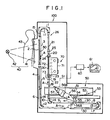
- FIG. 1 shows a radiation image recording and reproducing system for carrying out an embodiment of the radiation image recording and reproducing method according to the present invention.
- a radiation image recording and read-out apparatus 100 of this system is provided with a sheet circulation and conveyance means 26 comprising endless belts 1, 2, 3, 4, 5, 6, 7, 8, 9 and 10, guide rollers 11, 12, 13 and 14 rotated respectively by the endless belts 1, 6, 7 and 10, guide plates 15, 16, 17, 18, 19, 20 and 21, and nip rollers 22, 23, 24 and 25.
- a sheet circulation and conveyance means 26 comprising endless belts 1, 2, 3, 4, 5, 6, 7, 8, 9 and 10, guide rollers 11, 12, 13 and 14 rotated respectively by the endless belts 1, 6, 7 and 10, guide plates 15, 16, 17, 18, 19, 20 and 21, and nip rollers 22, 23, 24 and 25.
- the sheet circulation and conveyance system by way of example, four stimulable phosphor sheets are conveyed and circulated in spaced relation to each other in the direction as indicated by the arrow A by the endless belts 1 - 10 and the nip rolls 22
- the endless belts 2 and 3 are disposed so as to hold the stimulable phosphor sheets 30 vertically therebetween, and an image recording table 41 is positioned to the side (left side in the drawing) of the endlessbelts 2 and 3.
- a radiation source 42 e.g. an X-ray source, is spaced from the image recording table 41 to stand face to face with the endless belts 2 and 3.
- An image recording section 40 is constituted by the image recording table 41 and the radiation source 42.
- An image read-out section 50 is positioned at the lower right end of the sheet circulation and conveyance system 26.
- a laser beam source 51 is positioned above the endless belt 8 constituting a part of the image read-out section 50, and a mirror 53 and a galvanometer mirror 54 are positioned for scanning a laser beam 52 emitted by the laser beam source 51 in the width direction of the sheet 30 placed on the endless belt 8.
- the galvanometer mirror 54 is swung in both directions to scan the laser beam 52 in the main scanning direction on the sheet 30 carrying the radiation image stored thereon.
- the sheet 30 has been subjected to image recording at the image recording section 40 and then conveyed by the sheet circulation and conveyance means 26 to the image read-out section 50.
- a light guiding reflection mirror 55 and a light guide member 56 are positioned along the main scanning direction at the scanning portion of the laser beam 52 on the sheet 30.
- the sheet 30 When the sheet 30 is exposed to the laser beam 52, the sheet 30 emits light in proportion to the stored radiation energy.
- the light emitted by the sheet directly toward the light guide member 56 and the light emitted thereby and reflected by the light guiding reflection mirror 55 both enter the light guide member 56 from a light input face 56A thereof, and are guided inside of the light guide member 56 through total reflection to a light output face 56B thereof.
- the light is thus detected by a photomultiplier 57 connected to the light output face 56B of the light guide member 56.
- the sheet Simultaneously with the scanning of the sheet 30 by the laser beam 52 in the main scanning direction, the sheet is moved by the endless belt 8 in the sub-scanning direction, as indicated by the arrow A, approximately normal to the main scanning direction, so that the radiation image information is read out from the whole surface of the sheet 30.
- An electric image signal S1 obtained from the photomultiplier 57 is sent to an image processing circuit 60 for processing the electric image signal as required.
- the image signal thus processed is then sent to an image reproducing apparatus 61.
- the image reproducing apparatus may be a display device such as a CRT, or a device for recording a visible image by point-by-point scanning on a photographic film. Or, the image signal may be stored in a storage means such as a magnetic tape.
- the sheet 30 is conveyed by the endless belts 9 and 10 to pass between the guide plates 18, from where it is forwarded through the nip rollers 22 and the guide plates 19 to an erasing section 70.
- the erasing section 70 comprises a case 71 and many erasing light sources 72, e.g. fluorescent lamps, arranged within the case 71.
- a shutter 73 is opened, the sheet 30 is conveyed into the case 71 by the nip rollers 23. Then the shutter 73 is closed, and the erasing light sources 72 are turned on.
- the erasing light sources 72 mainly emit light having a wavelength within the stimulation wavelength range for the stimulable phosphor sheet 30.
- the nip rollers 24 are rotated and the sheet 30 is conveyed out of the erasing section 70. Then the sheet is conveyed between the guide plates 20 to the nip rollers 25, which further convey it between the guide plates 21 to the endless belt 1. The sheet 30 is then conveyed to the image recording section 40 in the same manner as described earlier and is again used for recording a radiation image.
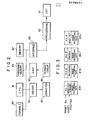
- the circulation of the sheets 30 within the aforesaid radiation image recording and read-out apparatus 100 is controlled by an electrical control circuit as shown in Figure 2. More specifically, instructions for the operation of the apparatus 100 are entered via a console 80 and corresponding operation signals output by the console 80 are fowarded to a CPU (central processing unit) 81 which on the basis of these signals and an operation program stored in a program memory 84 sends sheet conveyance control signals to a driver 82. In response to the received control signals, the driver 82 drives a sheet conveyance and circulation means 83 which comprises the endless belts 1 - 10, the nip rollers 22 - 25 as well as associated solenoids and the like.
- the electrical control circuit further comprises a group of sensors 86 (not shown in Figure 1) for detecting the presence of the sheets 30, the individual sensors of which are located at the image recording section 40, the image read-out section 50 and the erasing section 70 as well as at positions before and after these sections.
- the sheet detection signals output by the sensors 86 are amplified by a sensor amplifier 85 and sent to the CPU 81.
- the CPU 81 In response to these sheet detection signals, the CPU 81 times the stopping of the endless belts 1 - 10, the nip rollers 22 - 25 and the other elements of the sheet conveyance and circulating means 83 so as to stop the respective sheets 30 at predetermined positions.
- the CPU 81 is connected with a non-volatile memory 87 wherein are stored sheet supervision tables 87a, 87b, 87 C and 87d such as those shown in simple form in Figure 3.
- Each of these tables 87a - 87d is associated with a specific one of the four sheets 30 and includes the sheet number (the identifying code), position information and image recording information relating to the sheet concerned.
- Each sheet has its own specific sheet number which never changes, while the position information related to each sheet is updated each time the position of the sheet within the circulation path changes.
- the sheet 30 shown on the endless belt 7 is assigned the sheet number 1 (No.1) and the other sheets are labeled No. 2, No. 3 and No. 4 in order in the direction reverse to that of sheet conveyance indicated by the arrow A, then when the sheets are in the respective positions shown in Figure 1, the position information written into the respective sheet supervision tables 87a - 87d will be as shown in Figure 3.
- the CPU 81 Since the conveyance of the sheets 30 is controlled by the CPU 81 and the actual positions of the respective sheets are detected by the sensors 86, it is possible for the CPU 81 to ascertain which sheet is at which position on the basis of the sheet conveyance control signals sent to the driver 82 and the signals from the sensors 86. More specifically, as the sheets 30 pass through the image . recording, image read-out and erasing steps, the CPU 81 progressively rewrites the position information for the sheets 30 (No.1 - No.4) in the corresponding control tables 87a - 87d on the basis of the signals output by the sensors 86 and the program stored in the memory 84.
- the console 80 is used not only for entering the aforesaid operation instructions but also for entering, by means of a keyboard or the like, image recording information regarding the object 43 whose radiation image is to be recorded.
- This image recording information is written into the sheet supervision table 87a - 87d corresponding to the sheet 30 positioned at the image recording section 40 at that time. That is, taking the positioning of the sheets shown in Figure 1 as an example, since in this case the radiation image of the object 43 is to be recorded on the sheet 30 which has been labeled No. 2, the image recording information relating to the object 43 is written into the sheet supervision table 87b.
- This image recording information can include, for example, the ID number, name and complaint of the object 43 and data on the radiation image recording conditions such as the radiation dosage.
- the CPU 81 accesses the tables 87a - 87d and selects the one thereof whose position information is recorded as "read-out.” The CPU then reads the sheet number and image recording information from the selected table and sends this information to the image processing circuit 60 via an image processing circuit interface 88.
- the image recording information regarding the object 43 and the number of the sheet 30 on which the radiation image was recorded are displayed at the same time.
- the doctor who examines the reproduced radiation image for diagnostic purposes is thus able to refer to the image recording information in making his diagnosis. Also, if he observes any degradation in the quality of the reproduced radiation image which may be caused by deterioration of the stimulable phosphor sheet 30 on which it was recorded, he is at the same time able to read the sheet number of this sheet. From the sheet number it is a simple matter to identify which of the sheets in the radiation image recording and read-out apparatus 100 has deteriorated and then to replace it with a new one. At this time the position of the worn-out sheet 30 within the apparatus can easily be determined by reading the position information from the corresponding one of the sheet supervision tables 87a - 87d. Alternatively, the sheet numbers can be printed on the sheets 30 in visible form and the sheet to be replaced can be located by its sheet number.
- the sheet numbers are read by accessing the sheet supervision tables 87a - 87d on the basis of the position information.
- the sheet numbers are read by accessing the sheet supervision tables 87a - 87d on the basis of the position information.
- the identifying codes e.g. the sheet numbers
- the stimulable phosphor sheets 30 it is possible to record these codes directly on the stimulable phosphor sheets 30 and to read them out for reproduction at the same time as reading out the radiation image information.
- numbers instead of using numbers as the identifying codes for the stimulable phosphor sheets, it is possible to use characters, marks or the like.
- the stimulable phosphor sheets are reused by repeatedly conveying them along a Circulation path.
- the method of the present invention is, however, not limited to the use of such an image recording and read-out apparatus and can also be carried out using a system in which image recording and image read-out steps are carried out on a plurality of stimulable phosphor sheets as separate independent operations.
Landscapes
- Physics & Mathematics (AREA)
- General Physics & Mathematics (AREA)
- Radiography Using Non-Light Waves (AREA)
- Apparatus For Radiation Diagnosis (AREA)
- Analysing Materials By The Use Of Radiation (AREA)
Applications Claiming Priority (2)
| Application Number | Priority Date | Filing Date | Title |
|---|---|---|---|
| JP59218857A JPS6197646A (ja) | 1984-10-18 | 1984-10-18 | 放射線画像情報記録再生方法 |
| JP218857/84 | 1984-10-18 |
Publications (2)
| Publication Number | Publication Date |
|---|---|
| EP0178677A1 true EP0178677A1 (fr) | 1986-04-23 |
| EP0178677B1 EP0178677B1 (fr) | 1990-05-16 |
Family
ID=16726406
Family Applications (1)
| Application Number | Title | Priority Date | Filing Date |
|---|---|---|---|
| EP85113240A Expired - Lifetime EP0178677B1 (fr) | 1984-10-18 | 1985-10-18 | Dispositif pour l'enregistrement et la reproduction d'image de rayonnement |
Country Status (4)
| Country | Link |
|---|---|
| US (1) | US4760259A (fr) |
| EP (1) | EP0178677B1 (fr) |
| JP (1) | JPS6197646A (fr) |
| DE (1) | DE3577756D1 (fr) |
Cited By (1)
| Publication number | Priority date | Publication date | Assignee | Title |
|---|---|---|---|---|
| EP0345832A3 (en) * | 1984-10-30 | 1990-01-31 | Fuji Photo Film Co., Ltd. | Method of and apparatus for recording and reading out radiation image information |
Families Citing this family (6)
| Publication number | Priority date | Publication date | Assignee | Title |
|---|---|---|---|---|
| JPH0731373B2 (ja) * | 1987-02-24 | 1995-04-10 | コニカ株式会社 | 放射線画像情報読取装置 |
| JPS6420538A (en) * | 1987-07-16 | 1989-01-24 | Toshiba Corp | Radioactive diagnosing device |
| US4906847A (en) * | 1987-12-29 | 1990-03-06 | Fuji Photo Film Co., Ltd. | Radiation image read-out and reproducing apparatus |
| US5489494A (en) * | 1992-09-11 | 1996-02-06 | Ricoh Company, Ltd. | Image formation method using reversible thermosensitive recording material |
| AU2003257825A1 (en) * | 2002-08-16 | 2004-04-30 | Konica Minolta Holdings, Inc. | Radiation image reading device |
| JP5803353B2 (ja) * | 2011-07-04 | 2015-11-04 | パルステック工業株式会社 | X線回折測定装置及びイメージングプレートの管理方法 |
Citations (6)
| Publication number | Priority date | Publication date | Assignee | Title |
|---|---|---|---|---|
| DE1622320A1 (de) * | 1968-02-05 | 1971-01-07 | Maier Dipl Ing Alfred | Geraet zur Kennzeichnung von Roentgenfilmen |
| US3596094A (en) * | 1969-05-07 | 1971-07-27 | Leonard Corso | System and method for coding exposed x-ray films |
| US3845314A (en) * | 1970-02-25 | 1974-10-29 | United States Radium Corp | X-ray film identification means |
| US3849648A (en) * | 1973-12-10 | 1974-11-19 | Xonics Inc | Electron radiograph patient identification system |
| US4258264A (en) * | 1978-07-12 | 1981-03-24 | Fuji Photo Film Co., Ltd. | Method of and apparatus for reading out a radiation image recorded in a stimulable phosphor |
| EP0079557B1 (fr) * | 1981-11-14 | 1986-04-23 | Fuji Photo Film Co., Ltd. | Cassette pour film radiosensible |
Family Cites Families (10)
| Publication number | Priority date | Publication date | Assignee | Title |
|---|---|---|---|---|
| JPS5944333B2 (ja) * | 1978-07-12 | 1984-10-29 | 富士写真フイルム株式会社 | 放射線像変換方法 |
| JPS5618798A (en) * | 1979-07-24 | 1981-02-21 | Fuji Photo Film Co Ltd | Information recording method in radiation image record |
| JPS5866934A (ja) * | 1981-10-16 | 1983-04-21 | Fuji Photo Film Co Ltd | 放射線画像情報記録読取装置 |
| CA1192674A (fr) * | 1981-10-16 | 1985-08-27 | Hisatoyo Kato | Systeme d'enregistrement et de lecture d'images par rayonnement |
| JPS5824136A (ja) * | 1981-10-26 | 1983-02-14 | Fuji Photo Film Co Ltd | 放射線画像記録方式におけるデ−タ記録装置 |
| JPS5872043A (ja) * | 1981-10-26 | 1983-04-28 | Fuji Photo Film Co Ltd | 蓄積性螢光体情報記録装置 |
| JPH0685045B2 (ja) * | 1982-05-19 | 1994-10-26 | 富士写真フイルム株式会社 | 放射線画像情報変換方法および装置 |
| JPS5928145A (ja) * | 1982-08-09 | 1984-02-14 | Fuji Photo Film Co Ltd | 放射線画像再生装置 |
| JPS5928146A (ja) * | 1982-08-09 | 1984-02-14 | Fuji Photo Film Co Ltd | 放射線画像再生装置 |
| JPH0690405B2 (ja) * | 1983-03-11 | 1994-11-14 | 富士写真フイルム株式会社 | 放射線画像記録再生装置 |
-
1984
- 1984-10-18 JP JP59218857A patent/JPS6197646A/ja active Granted
-
1985
- 1985-10-18 US US06/789,260 patent/US4760259A/en not_active Expired - Lifetime
- 1985-10-18 EP EP85113240A patent/EP0178677B1/fr not_active Expired - Lifetime
- 1985-10-18 DE DE8585113240T patent/DE3577756D1/de not_active Expired - Lifetime
Patent Citations (6)
| Publication number | Priority date | Publication date | Assignee | Title |
|---|---|---|---|---|
| DE1622320A1 (de) * | 1968-02-05 | 1971-01-07 | Maier Dipl Ing Alfred | Geraet zur Kennzeichnung von Roentgenfilmen |
| US3596094A (en) * | 1969-05-07 | 1971-07-27 | Leonard Corso | System and method for coding exposed x-ray films |
| US3845314A (en) * | 1970-02-25 | 1974-10-29 | United States Radium Corp | X-ray film identification means |
| US3849648A (en) * | 1973-12-10 | 1974-11-19 | Xonics Inc | Electron radiograph patient identification system |
| US4258264A (en) * | 1978-07-12 | 1981-03-24 | Fuji Photo Film Co., Ltd. | Method of and apparatus for reading out a radiation image recorded in a stimulable phosphor |
| EP0079557B1 (fr) * | 1981-11-14 | 1986-04-23 | Fuji Photo Film Co., Ltd. | Cassette pour film radiosensible |
Cited By (1)
| Publication number | Priority date | Publication date | Assignee | Title |
|---|---|---|---|---|
| EP0345832A3 (en) * | 1984-10-30 | 1990-01-31 | Fuji Photo Film Co., Ltd. | Method of and apparatus for recording and reading out radiation image information |
Also Published As
| Publication number | Publication date |
|---|---|
| JPS6197646A (ja) | 1986-05-16 |
| EP0178677B1 (fr) | 1990-05-16 |
| JPH0588451B2 (fr) | 1993-12-22 |
| DE3577756D1 (de) | 1990-06-21 |
| US4760259A (en) | 1988-07-26 |
Similar Documents
| Publication | Publication Date | Title |
|---|---|---|
| US4498006A (en) | Radiation image read-out method and apparatus | |
| US4320296A (en) | Method of and apparatus for recording image processing data in radiation image recording system | |
| EP0125800B1 (fr) | Dispositif pour l'enregistrement et la reproduction d'image de rayonnement | |
| US4705953A (en) | Radiation image recording and read-out apparatus with object data output capability | |
| US5072119A (en) | Radiation image read-out apparatus and erasing apparatus | |
| US4760259A (en) | Radiation image recording and reproducing method | |
| US4578581A (en) | Radiation image read-out method and apparatus | |
| US4760256A (en) | Radiation image recording and read-out apparatus | |
| US4960993A (en) | Radiating image read-out and displaying apparatus | |
| US5233519A (en) | Radiation image diagnostic apparatus | |
| JP3260028B2 (ja) | 蓄積性蛍光体シートの残留ノイズ消去方法および装置 | |
| EP0181518B1 (fr) | Procédé et dispositif pour l'enregistrement et la reproduction d'images de rayonnement | |
| US4896038A (en) | Radiation image read-out method and apparatus | |
| EP0172417B1 (fr) | Dispositif pour l'enregistrement et la reproduction d'image de rayonnement | |
| US4885468A (en) | Radiation image recording apparatus, and stimulable phosphor sheet feeding and loading apparatus | |
| US5015854A (en) | Radiation image displaying apparatus | |
| US5260573A (en) | Radiographical image reading apparatus | |
| US4939367A (en) | Recording and read-out apparatus | |
| EP0183040B1 (fr) | Dispositif pour l'enregistrement et la reproduction d'image de rayonnement | |
| US4810887A (en) | Radiation image read-out method and apparatus | |
| EP0178675A1 (fr) | Dispositif pour la reproduction d'image de rayonnement | |
| US4733076A (en) | Radiation image recording and read-out apparatus | |
| EP0183063A2 (fr) | Dispositif pour l'enregistrement et la reproduction d'image de rayonnement | |
| JPH0680457B2 (ja) | 放射線画像情報記録読取装置 | |
| JPH08254600A (ja) | デジタルラジオグラフイーにおける品質保証の方法 |
Legal Events
| Date | Code | Title | Description |
|---|---|---|---|
| PUAI | Public reference made under article 153(3) epc to a published international application that has entered the european phase |
Free format text: ORIGINAL CODE: 0009012 |
|
| AK | Designated contracting states |
Kind code of ref document: A1 Designated state(s): DE FR NL |
|
| 17P | Request for examination filed |
Effective date: 19860606 |
|
| 17Q | First examination report despatched |
Effective date: 19871028 |
|
| GRAA | (expected) grant |
Free format text: ORIGINAL CODE: 0009210 |
|
| AK | Designated contracting states |
Kind code of ref document: B1 Designated state(s): DE FR NL |
|
| REF | Corresponds to: |
Ref document number: 3577756 Country of ref document: DE Date of ref document: 19900621 |
|
| ET | Fr: translation filed | ||
| PLBE | No opposition filed within time limit |
Free format text: ORIGINAL CODE: 0009261 |
|
| STAA | Information on the status of an ep patent application or granted ep patent |
Free format text: STATUS: NO OPPOSITION FILED WITHIN TIME LIMIT |
|
| 26N | No opposition filed | ||
| PGFP | Annual fee paid to national office [announced via postgrant information from national office to epo] |
Ref country code: NL Payment date: 20040929 Year of fee payment: 20 |
|
| PGFP | Annual fee paid to national office [announced via postgrant information from national office to epo] |
Ref country code: FR Payment date: 20041020 Year of fee payment: 20 |
|
| PGFP | Annual fee paid to national office [announced via postgrant information from national office to epo] |
Ref country code: DE Payment date: 20041130 Year of fee payment: 20 |
|
| PG25 | Lapsed in a contracting state [announced via postgrant information from national office to epo] |
Ref country code: NL Free format text: LAPSE BECAUSE OF EXPIRATION OF PROTECTION Effective date: 20051018 |
|
| NLV7 | Nl: ceased due to reaching the maximum lifetime of a patent |
Effective date: 20051018 |