EP0179030A2 - Absaugehaube - Google Patents
Absaugehaube Download PDFInfo
- Publication number
- EP0179030A2 EP0179030A2 EP85850246A EP85850246A EP0179030A2 EP 0179030 A2 EP0179030 A2 EP 0179030A2 EP 85850246 A EP85850246 A EP 85850246A EP 85850246 A EP85850246 A EP 85850246A EP 0179030 A2 EP0179030 A2 EP 0179030A2
- Authority
- EP
- European Patent Office
- Prior art keywords
- casing
- air supply
- air
- supply device
- wall
- Prior art date
- Legal status (The legal status is an assumption and is not a legal conclusion. Google has not performed a legal analysis and makes no representation as to the accuracy of the status listed.)
- Granted
Links
Images
Classifications
-
- B—PERFORMING OPERATIONS; TRANSPORTING
- B08—CLEANING
- B08B—CLEANING IN GENERAL; PREVENTION OF FOULING IN GENERAL
- B08B15/00—Preventing escape of dirt or fumes from the area where they are produced; Collecting or removing dirt or fumes from that area
- B08B15/02—Preventing escape of dirt or fumes from the area where they are produced; Collecting or removing dirt or fumes from that area using chambers or hoods covering the area
- B08B15/023—Fume cabinets or cupboards, e.g. for laboratories
Definitions
- the present invention relates to an air supply device including an enlongated blow opening for blowing ejector air directed towards an exhaust device for entraining polluted air which is to be exhausted.
- Exhaust devices of such a kind are known from SE-B-7904443-4 and SE-8305034-4, these devices comprising an elongated exhaust hood having a rear hood wall and adjoining side walls, the air supply device being formed as a box-like casing arranged at the lower edge of the rear hood wall and having at the top thereof an elongated blow opening in the form of a row of small holes. If such an exhaust hood is arranged on a work bench, e.g. in a laboratory, the row of holes will be located somewhat above the bench surface corresponding to the height of the casing, and therefore the ejector air will be effective only above this level and, thus, cannot entrain heavy gases and air-borne impurity particles gathered closely above the bench surface.
- a method to entrain such heavy gases and impurity particles is of course to lower the air supply casing into the work bench itself or the like, so that the blow openings will be located in the plane of the bench surface.
- Such an arrangement involves a non-desired modification of the work bench which might be complicated, expensive and difficult to alter.
- the main object of the present invention is therefore to achieve an air supply device of the kind referred to above, which can be mounted freely relative to the underlying or surrounding surfaces and, in spite thereof,will secure an effective entrainment of air around the entire casing.
- the air supply device comprises a casing provided with a shield wall adjacent to one side of the blow opening, so that polluted air or other gases, which are to be exhausted, are caused to flow around the casing and to be entrained adjacent to the other side of the blow opening.
- a suction effect will appear at the side of the casing opposite to the shield wall, e.g,.at the underside and polluted air and other gases will be caused to flow towards the casing, around the same on both sides (e.g. at the top and atthebottom), and thereafter be united into a common stream being influenced by the ejector air and possible guiding surfaces (e.g. a rear hood wall).
- the casing may advantegeously be located at some distance from a hood wall adjoining said exhaust device, so that the hood wall forms a guiding surface being either planar or curved for a desired deflection of the stream.
- the shield wall of the casing may be inclined towards the hood wall, so that the ejector air flows obliquely towards the hood wall and effectively conveys polluted air and other gases, which have entered into the space between the casing and the hood wall.
- the casing may be disposed at some distance above a table or bench surface or the like, i.e. in case the exhaust device is intended to be placed on a table or a bench. Then, a gap is formed between the casing and the bench surface, through which polluted air and other gases, in particular heavy gases, enters by suction. It is also conceivable to let the bench surface continuously adjoin a rear hood wall, possibly by way of special deflecting plates being connected to the respective surfaces, e.g. with a rounded profile.
- the casing also has a rounded profile, in particular at the side opposite to the shield wall, e.g. the underside, in order to enhance a low-turbulent flow of polluted air and other gases around the circumferential surface of the casing.
- the casing and the shield wall in one piece, e.g. of galvnized plate, acid- proof plate, or of rigid thermoplastic material, e.g. olefine plastic, such as polyethylene or polypropylene, or vinlychloride plastic, such as polyvinylchloride, or a fibre- reinforced thermosetting plastic material, e.g. glass- fibre-reinforced polyester.
- rigid thermoplastic material e.g. olefine plastic, such as polyethylene or polypropylene, or vinlychloride plastic, such as polyvinylchloride, or a fibre- reinforced thermosetting plastic material, e.g. glass- fibre-reinforced polyester.
- a plate If a plate is used, it can easily be bent in such a way that an edge portion forms an essentially plan shield wall, a mid-portion forms the casing itself with a rounded profile and the opposite edge portion forms a short wall portion extending essentially in parallel to the shield wall and forming a slot constituting the blow opening of the casing.
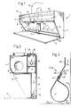
- the exhaust hood 1 in Fig. 1 is placed onto a tabel 2 and comprises, as known per se, an upper hood portion 3, consisting of a vertical front hood wall 4, an upper horizontal hood wall 5, side walls 6 and 7 and a rear hood wall 8, the side walls 6,7 and the rear hood wall 8 being extended downwardly all the way down to the table 2.
- an upper hood portion 3 consisting of a vertical front hood wall 4, an upper horizontal hood wall 5, side walls 6 and 7 and a rear hood wall 8, the side walls 6,7 and the rear hood wall 8 being extended downwardly all the way down to the table 2.
- a deflection housing 9 which is provided with two exhaust openings 10, 11 (only the opening 11 is visible in Fig. 1) facing each side wall 6 and 7, respectively, and connected via an exhaust channel 12 (Fig. 1) to a non-shown exhaust air fan.
- the deflection housing 9 comprises deflection and shield plates (here not shown) such as those described in detail in the above-mentioned SE 8305034-4.
- deflection and shield plates such as those described in detail in the above-mentioned SE 8305034-4.
- two co-axial rotational flow patterns are devloped in the hood between each side wall 6 and 7, respectively, and the respective exhaust opening 10,11 around the dash-dotted axis L in Fig. 1. These rotational flows absorb polluted air and other gases, which are thus exhausted via the deflection housing 9 and the exhaust channel 12.
- an especially designed air supply device is adapted to blow ejector air upwardly from the lower part of the rear hood wall 8,
- This air supply device comprises an inlet opening 13 (Fig. 2) located at the top of the upper hood wall 5 behind the deflection housing 9 and connected to a vertical feed channel 14, which contains an air supply fan 15 and extends centrally adjacent to the rear hood wall 8, .as appears from Figs. 1 and 2.
- a sound-absorbing plate 16 is disposed in order to reduce the noise generated by the fan.
- the feed channel 14 is connected at the lower end to two air supply casing portions 17,18 extending in parallel to the rear hood wall 8 at some distance from the lower edge portion thereof and, thus, also in parallel to the axis L, around which the two rotational flows are generated in the upper portion of the hood 1.
- Each air supply casing 17,18 is fastened at its ends, in a manner not shown, to the side walls 6 and 7, respectively (so that the outer end is closed) as well as to the lower end portion of the feed channel 14 by way of corresponding side openings 19 (one is visible in Fig. 2).
- each air supply casing 17,18 consists of a bent plate having upper front portions 19,20, a substantially tubular, rounded portion 21 adjoining thereto, and a relatively short, rear portion 22, which extends in parallel to the portion 19. Between the portiona 19 and 22, an elongate blow opening 23 is formed, through which inlet air is blown as ejector air adjacent to the rear hood wall 8.
- the upper, front portions 19,20 serve as a shield wall against polluted air and other gases flowing from the area above the table 2 in the direction towards the rear hood wall 8.
- the main entrainment is effected in the region behind the shield wall portions 19,20, namely between these portions and the rear hood wall 8, mainly in the region indicated by the arrow P1 in Fig. 3.
- the ejector air and the entrained air as well as other gases thereafter flow upwardly, while being shielded behind the wall portion 20, in a common stream P3, which in the region above the upper edge of the air supply casing continues upwardly along the hood wall 8 for entraining air at a higher level and other, lighter gases to be exhausted.
- a stream directed towards the rear hood wall 8 will be generated, below as well as above the air supply casing portions 17,18.
- the shield wall portion 19 is inclined at about 30° relative to the vertical, rear hood wall 8 and merges with an end portion 20 extending vertically and thus in.parallel to said hood wall 8, resulting in a good guiding of the upwardly flowing air therebetween.
- the width of the blow opening 23 is kept at a desired value in that the plate, upon being bent, is slightly prestressed in a widening direction, and are simple rivet or screw fasteners 24 distributed along the longitudinal direction of the casing .portions so as to keep the plate in its shown position with a well-defined blow opening 23.
- the air supply casing portions 17,18 may of course be replaced by only one elongated casing being fed from one end thereof adjacent to the corresponding side wall. Furthermore, the detailed design of the air supply casing may be modified at wish within the scope of the claims. In principal, a circular- cylindrical tube provided with obliquely upwardly facing hole openings at its rear side may possibly be used, wherein the upper portion of such a tube forms a shield, though with reduced shielding effect as compared to the shown example.
- the shield wall is not necessarily inclided, and the casing profile may also be modified at wish.
- the air supply casing may alternatively be suspended in brackets extending from the rear hood wall or may rest on supports directly on the table surface, possibly as a loose unit with hose connections to a supply air fan.
- the air supply casing it is also possible to suspend the air supply casing entirely freely at a desired distance below an exhaust hood, the design of which is not either directly related to the inventive concept.
- the essential feature is that a shield wall is disposed at one side of the blow opening, so that entrainment will occur adjacent to the other side of the blow opening, thereby resulting in a certain suction effect causing the polluted air or other gases to flow around the casing.
- the air supply opening may consist of a simple slot, a row of holes or a set of nozzles.
- the air supply opening should be elongated but not necessarily rectilinear.
- the air supply device according to the invention may advantageously be used in closed exhaust hoods.
Landscapes
- Ventilation (AREA)
- Saccharide Compounds (AREA)
- Pharmaceuticals Containing Other Organic And Inorganic Compounds (AREA)
- Respiratory Apparatuses And Protective Means (AREA)
- Jet Pumps And Other Pumps (AREA)
- Medicines That Contain Protein Lipid Enzymes And Other Medicines (AREA)
- Cleaning In General (AREA)
- Peptides Or Proteins (AREA)
- Superstructure Of Vehicle (AREA)
- Nozzles (AREA)
- Prevention Of Fouling (AREA)
- Seal Device For Vehicle (AREA)
- Outer Garments And Coats (AREA)
- Endoscopes (AREA)
- Nitrogen Condensed Heterocyclic Rings (AREA)
Priority Applications (1)
| Application Number | Priority Date | Filing Date | Title |
|---|---|---|---|
| AT85850246T ATE35517T1 (de) | 1984-08-20 | 1985-07-24 | Absaugehaube. |
Applications Claiming Priority (2)
| Application Number | Priority Date | Filing Date | Title |
|---|---|---|---|
| SE8404153A SE8404153L (sv) | 1984-08-20 | 1984-08-20 | Inblasningsanordning for inblasning av ejektorluft vid en utsugningskapas bakre vegg |
| SE8404153 | 1984-08-20 |
Publications (3)
| Publication Number | Publication Date |
|---|---|
| EP0179030A2 true EP0179030A2 (de) | 1986-04-23 |
| EP0179030A3 EP0179030A3 (en) | 1986-06-04 |
| EP0179030B1 EP0179030B1 (de) | 1988-07-06 |
Family
ID=20356749
Family Applications (1)
| Application Number | Title | Priority Date | Filing Date |
|---|---|---|---|
| EP85850246A Expired EP0179030B1 (de) | 1984-08-20 | 1985-07-24 | Absaugehaube |
Country Status (9)
| Country | Link |
|---|---|
| US (1) | US4637302A (de) |
| EP (1) | EP0179030B1 (de) |
| JP (1) | JPS6162742A (de) |
| AT (1) | ATE35517T1 (de) |
| DE (1) | DE3563593D1 (de) |
| DK (1) | DK171171B1 (de) |
| FI (1) | FI81977C (de) |
| NO (1) | NO157286C (de) |
| SE (1) | SE8404153L (de) |
Families Citing this family (5)
| Publication number | Priority date | Publication date | Assignee | Title |
|---|---|---|---|---|
| US5065668A (en) * | 1990-06-11 | 1991-11-19 | Centercore, Inc. | Air circulation system |
| US20120077425A1 (en) * | 2010-09-29 | 2012-03-29 | University Of Medicine And Dentistry Of New Jersey | Accessible Hood Sash |
| JP5604699B2 (ja) * | 2011-09-13 | 2014-10-15 | 渡邉 隆太郎 | レンジフード |
| WO2019072059A1 (zh) * | 2017-10-10 | 2019-04-18 | 杭州老板电器股份有限公司 | 集烟组件、油烟机、侧吸式油烟机、两侧拢烟中部进风的油烟机、带有风帆的吸油烟机及中央油烟净化设备 |
| US11629861B2 (en) * | 2019-10-28 | 2023-04-18 | Lg Electronics Inc. | Kitchen hood with slim profile |
Family Cites Families (6)
| Publication number | Priority date | Publication date | Assignee | Title |
|---|---|---|---|---|
| US3400649A (en) * | 1967-01-26 | 1968-09-10 | Donald D. Jensen | Ventilating system including fume removal means |
| US4043319A (en) * | 1975-09-18 | 1977-08-23 | Jensen Donald D | Exhaust hood |
| GB1595840A (en) * | 1978-05-30 | 1981-08-19 | Longworth A L | Fume cupboards |
| US4211154A (en) * | 1978-09-20 | 1980-07-08 | Eakes Marion L | Apparatus for improving the collection of gases into a suction orifice |
| SE419830B (sv) * | 1979-05-21 | 1981-08-31 | Leif Ingemar Lind | Sett och anordning for utsugning av fororenad luft |
| DE3205689A1 (de) * | 1982-02-17 | 1983-08-25 | Heinrich Ing.(grad.) 5205 St. Augustin Hilbers | Gasabzugschrank mit belueftungsschleier und ablufteinrichtung |
-
1984
- 1984-08-20 SE SE8404153A patent/SE8404153L/ not_active IP Right Cessation
-
1985
- 1985-07-24 EP EP85850246A patent/EP0179030B1/de not_active Expired
- 1985-07-24 AT AT85850246T patent/ATE35517T1/de not_active IP Right Cessation
- 1985-07-24 DE DE8585850246T patent/DE3563593D1/de not_active Expired
- 1985-08-08 FI FI853051A patent/FI81977C/fi not_active IP Right Cessation
- 1985-08-16 US US06/766,145 patent/US4637302A/en not_active Expired - Lifetime
- 1985-08-19 NO NO853260A patent/NO157286C/no not_active IP Right Cessation
- 1985-08-19 DK DK375485A patent/DK171171B1/da not_active IP Right Cessation
- 1985-08-19 JP JP60180599A patent/JPS6162742A/ja active Pending
Also Published As
| Publication number | Publication date |
|---|---|
| NO157286C (no) | 1988-02-24 |
| FI853051A0 (fi) | 1985-08-08 |
| FI81977C (fi) | 1991-01-10 |
| NO853260L (no) | 1986-02-21 |
| EP0179030B1 (de) | 1988-07-06 |
| DK375485D0 (da) | 1985-08-19 |
| SE442958B (sv) | 1986-02-10 |
| DK171171B1 (da) | 1996-07-15 |
| FI81977B (fi) | 1990-09-28 |
| SE8404153D0 (sv) | 1984-08-20 |
| DK375485A (da) | 1986-02-21 |
| EP0179030A3 (en) | 1986-06-04 |
| SE8404153L (sv) | 1986-02-10 |
| JPS6162742A (ja) | 1986-03-31 |
| DE3563593D1 (en) | 1988-08-11 |
| FI853051L (fi) | 1986-02-21 |
| ATE35517T1 (de) | 1988-07-15 |
| US4637302A (en) | 1987-01-20 |
| NO157286B (no) | 1987-11-16 |
Similar Documents
| Publication | Publication Date | Title |
|---|---|---|
| US3978777A (en) | Ventilating apparatus | |
| EP2240726B1 (de) | Abzugshaube mit einer abzugsverbesserungsvorrichtung | |
| JP2868289B2 (ja) | 蒸気等の吸引方法および装置 | |
| US4125062A (en) | Ventilating system for industrial machines | |
| US4047519A (en) | Ventilating apparatus | |
| US4286572A (en) | Ventilating hood | |
| US4622888A (en) | Hoods for the extraction of gases, vapors and suspended material | |
| US4584929A (en) | Exhaust device | |
| US4729775A (en) | Device for scrubbing a polluted gas | |
| US4280400A (en) | Fume cupboards | |
| US5178654A (en) | Wet scrubber apparatus | |
| US6506109B1 (en) | Fume hood with air chamber | |
| US4637302A (en) | Air supply device | |
| EP0466687B1 (de) | Sauganordnung | |
| JPH0663934A (ja) | 石材加工装置用エアカーテン方式による粉塵抑止装置 | |
| US6569007B2 (en) | Fume hood with air chamber and pressure pipe | |
| US4700688A (en) | Ventilating hood | |
| US4690042A (en) | Computer environment filter apparatus having wing with internal baffles | |
| JP3326306B2 (ja) | ドラフトチャンバー | |
| CA1069749A (en) | Ventilating apparatus | |
| KR930003968A (ko) | 가스 방사물용 수집 장치 | |
| CA1194812A (en) | Trim separator | |
| JPH03258483A (ja) | レーザ加工機の集塵装置 | |
| US4985056A (en) | Device for purifying contaminated gas | |
| KR20260035455A (ko) | 에어 샤워장치 |
Legal Events
| Date | Code | Title | Description |
|---|---|---|---|
| PUAI | Public reference made under article 153(3) epc to a published international application that has entered the european phase |
Free format text: ORIGINAL CODE: 0009012 |
|
| PUAL | Search report despatched |
Free format text: ORIGINAL CODE: 0009013 |
|
| AK | Designated contracting states |
Kind code of ref document: A2 Designated state(s): AT BE DE FR GB IT LU NL SE |
|
| AK | Designated contracting states |
Kind code of ref document: A3 Designated state(s): AT BE DE FR GB IT LU NL SE |
|
| 17P | Request for examination filed |
Effective date: 19861020 |
|
| 17Q | First examination report despatched |
Effective date: 19870507 |
|
| ITF | It: translation for a ep patent filed | ||
| GRAA | (expected) grant |
Free format text: ORIGINAL CODE: 0009210 |
|
| AK | Designated contracting states |
Kind code of ref document: B1 Designated state(s): AT BE DE FR GB IT LU NL SE |
|
| PG25 | Lapsed in a contracting state [announced via postgrant information from national office to epo] |
Ref country code: SE Effective date: 19880706 Ref country code: NL Effective date: 19880706 Ref country code: AT Effective date: 19880706 |
|
| REF | Corresponds to: |
Ref document number: 35517 Country of ref document: AT Date of ref document: 19880715 Kind code of ref document: T |
|
| PG25 | Lapsed in a contracting state [announced via postgrant information from national office to epo] |
Ref country code: LU Free format text: LAPSE BECAUSE OF NON-PAYMENT OF DUE FEES Effective date: 19880731 |
|
| REF | Corresponds to: |
Ref document number: 3563593 Country of ref document: DE Date of ref document: 19880811 |
|
| ET | Fr: translation filed | ||
| NLV1 | Nl: lapsed or annulled due to failure to fulfill the requirements of art. 29p and 29m of the patents act | ||
| PLBE | No opposition filed within time limit |
Free format text: ORIGINAL CODE: 0009261 |
|
| STAA | Information on the status of an ep patent application or granted ep patent |
Free format text: STATUS: NO OPPOSITION FILED WITHIN TIME LIMIT |
|
| 26N | No opposition filed | ||
| ITTA | It: last paid annual fee | ||
| PGFP | Annual fee paid to national office [announced via postgrant information from national office to epo] |
Ref country code: FR Payment date: 20010712 Year of fee payment: 17 |
|
| PGFP | Annual fee paid to national office [announced via postgrant information from national office to epo] |
Ref country code: DE Payment date: 20010716 Year of fee payment: 17 |
|
| PGFP | Annual fee paid to national office [announced via postgrant information from national office to epo] |
Ref country code: GB Payment date: 20010718 Year of fee payment: 17 |
|
| PGFP | Annual fee paid to national office [announced via postgrant information from national office to epo] |
Ref country code: BE Payment date: 20010918 Year of fee payment: 17 |
|
| REG | Reference to a national code |
Ref country code: GB Ref legal event code: IF02 |
|
| PG25 | Lapsed in a contracting state [announced via postgrant information from national office to epo] |
Ref country code: GB Free format text: LAPSE BECAUSE OF NON-PAYMENT OF DUE FEES Effective date: 20020724 |
|
| PG25 | Lapsed in a contracting state [announced via postgrant information from national office to epo] |
Ref country code: BE Free format text: LAPSE BECAUSE OF NON-PAYMENT OF DUE FEES Effective date: 20020731 |
|
| BERE | Be: lapsed |
Owner name: A.B. *BAHCO VENTILATION Effective date: 20020731 |
|
| PG25 | Lapsed in a contracting state [announced via postgrant information from national office to epo] |
Ref country code: DE Free format text: LAPSE BECAUSE OF NON-PAYMENT OF DUE FEES Effective date: 20030201 |
|
| GBPC | Gb: european patent ceased through non-payment of renewal fee |
Effective date: 20020724 |
|
| PG25 | Lapsed in a contracting state [announced via postgrant information from national office to epo] |
Ref country code: FR Free format text: LAPSE BECAUSE OF NON-PAYMENT OF DUE FEES Effective date: 20030331 |
|
| REG | Reference to a national code |
Ref country code: FR Ref legal event code: ST |