EP0179041A2 - Segment de coupe - Google Patents
Segment de coupe Download PDFInfo
- Publication number
- EP0179041A2 EP0179041A2 EP85850328A EP85850328A EP0179041A2 EP 0179041 A2 EP0179041 A2 EP 0179041A2 EP 85850328 A EP85850328 A EP 85850328A EP 85850328 A EP85850328 A EP 85850328A EP 0179041 A2 EP0179041 A2 EP 0179041A2
- Authority
- EP
- European Patent Office
- Prior art keywords
- cutter
- exhaust
- segment according
- cutters
- steam
- Prior art date
- Legal status (The legal status is an assumption and is not a legal conclusion. Google has not performed a legal analysis and makes no representation as to the accuracy of the status listed.)
- Granted
Links
- 239000000463 material Substances 0.000 claims abstract description 19
- 238000000034 method Methods 0.000 claims abstract description 9
- 239000002023 wood Substances 0.000 claims abstract description 6
- 239000002245 particle Substances 0.000 claims description 7
- 230000015572 biosynthetic process Effects 0.000 claims description 2
- 238000005755 formation reaction Methods 0.000 claims description 2
- 230000000694 effects Effects 0.000 description 3
- 239000000835 fiber Substances 0.000 description 3
- 238000004519 manufacturing process Methods 0.000 description 2
- 230000009172 bursting Effects 0.000 description 1
- 239000002657 fibrous material Substances 0.000 description 1
- 238000009434 installation Methods 0.000 description 1
- 238000011835 investigation Methods 0.000 description 1
- 238000009834 vaporization Methods 0.000 description 1
- 230000008016 vaporization Effects 0.000 description 1
- XLYOFNOQVPJJNP-UHFFFAOYSA-N water Substances O XLYOFNOQVPJJNP-UHFFFAOYSA-N 0.000 description 1
Images
Classifications
-
- D—TEXTILES; PAPER
- D21—PAPER-MAKING; PRODUCTION OF CELLULOSE
- D21D—TREATMENT OF THE MATERIALS BEFORE PASSING TO THE PAPER-MAKING MACHINE
- D21D1/00—Methods of beating or refining; Beaters of the Hollander type
- D21D1/20—Methods of refining
- D21D1/30—Disc mills
- D21D1/306—Discs
-
- B—PERFORMING OPERATIONS; TRANSPORTING
- B02—CRUSHING, PULVERISING, OR DISINTEGRATING; PREPARATORY TREATMENT OF GRAIN FOR MILLING
- B02C—CRUSHING, PULVERISING, OR DISINTEGRATING IN GENERAL; MILLING GRAIN
- B02C7/00—Crushing or disintegrating by disc mills
- B02C7/11—Details
- B02C7/12—Shape or construction of discs
-
- B—PERFORMING OPERATIONS; TRANSPORTING
- B27—WORKING OR PRESERVING WOOD OR SIMILAR MATERIAL; NAILING OR STAPLING MACHINES IN GENERAL
- B27L—REMOVING BARK OR VESTIGES OF BRANCHES; SPLITTING WOOD; MANUFACTURE OF VENEER, WOODEN STICKS, WOOD SHAVINGS, WOOD FIBRES OR WOOD POWDER
- B27L11/00—Manufacture of wood shavings, chips, powder, or the like; Tools therefor
- B27L11/08—Manufacture of wood shavings, chips, powder, or the like; Tools therefor of wood fibres, e.g. produced by tearing
Definitions
- the present invention concerns a cutter segment for a disc grinder or the like, said grinder consisting of two oppositely placed cutters made up of several cutter segments attached to each other, at least one of the cutters being rotatable. said cutter segments being provided with a rough surface or with teeth and grooves for the grinding of material such as wood chips.
- a mechanical disc grinder may be used to reduce fibrous material such as wood chips to fibers suitable for paper production.
- This defibration process consists in feeding the chips into a grinder. where the material is passed between two grinding cutters placed oppositely. The cutter surfaces are full of grooves and longish protrusions, i.e. teeth. and at least one of the cutters rotates. In this way the material undergoes a very rough treatment between the cutters and is reduced to fibers.
- Prior-art cutters which for ease of manufacture and installation are composed of several segments, have the drawback that the defibrated material contains undefibrated wood particles or splinters. while part of the fibres are over-ground and destroyed.
- big grinders operated at considerable power levels. vaporization of the water contained in the wood produces so much steam that. because of the steam pressure, it is difficult to maintain a constant distance between the grinder cutters, which is important in view of product quality.
- the steam bursting out of the grinder in an uncontrolled manner often involves significant trouble in the supply of material into the grinder.
- the object of the present invention is to achieve a cutter segment that eliminates the above-mentioned problems and can be manufactured at a moderate cost for industrial use.
- the cutter segment of the invention is characterized in that the segments of at least one of the cutters are provided with one or more exhaust channels essentially larger in section than the aforesaid grooves. Through these channels the steam is exhausted quickly and in a controlled manner. so that the steam pressure between the cutters cannot rise high enough to impede control of the cutter distance. Also. when the steam ia exhausted from the grinder in a controlled fashion, it will not disturb the flow of material into the grinder.
- An advantageous embodiment of the invention is characterized in that the exhaust channels serve primarily to exhaust the steam produced in the grinding process, and that the velocity of the steam flowing in the exhaust channel depends on the sectional area of the channel. and that when the velocity of the exhaust steam is over 10 m/s or about 10 - 50 m/s. the defibrated material is drawn by the steam flow into the exhaust channel and thus removed from the space between the cutters. As the defibrated material is quickly removed by the steam flow. over-grinding of the fibres is prevented, while less energy is consumed in the process.
- Another advangtageous embodiment of the invention is characterized in that the exhaust channel is placed at an angle to the cutter radius, the most advantageous angle being 30-60 *.
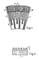
- Fig. 1 presents a known cutter segment:
- a typical prior-art cutter segment is divided into three zones in the direction of material passage.
- the teeth 5 and grooves 6 in each zone are of a different size, corresponding to the size of the material particles to be ground.
- the steam produced in the process extrudes from the grinder through the grooves 6 and the very narrow space (about 200 microm.) between the cutters. As the groove space available during grinding for the steam to escape is very small, this results in the problems referred to above.
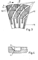
- the cutter segment of the invention comprises exhaust channels 7. which to best advantage are incorporated to in the rotating cutter. called rotor.
- the direction of rotation, seen from the cutting side. is as shown by the arrow 8.
- the sectional area 9 of the exhaust channel 7 is considerably larger than that of a conventional groove 6 between the cutter teeth. which means that the steam is efficiently exhausted through the channel. If the exhaust channel 7 is made to correct dimensions so as to provide an appropriate passage for the amount of steam oroduced. the violent flow of steam carries the finest material. i.e. the fibers. along with it out of the grinder.
- the velocity of the steam flow in the channel. according to investigations. should preferably be within 10-50 m/s.
- the exhaust channel is placed at a correct angle (34-60°) to the cutter radius so as to produce a certain impeding effect, the larger particles that have not yet been defibrated are lifted back up from the channel by the mutual effect of the inertia of the particles and the centrifugal force driving them outward in the direction of the cutter radius, to be further ground by the cutter teeth.
- This arrangement also compensates for the effect of the centrifugal force produced by the rotor cutter that tends to carry the material outwards.
- exhaust channels placed only in the outer zones of the cutter segment, leaving the material supply zone 14 without such channels. This is possible because the teeth in the supply zone are large and the grooves between them provide sufficient space for the steam even without specific exhaust channels.
Landscapes
- Engineering & Computer Science (AREA)
- Life Sciences & Earth Sciences (AREA)
- Manufacturing & Machinery (AREA)
- Mechanical Engineering (AREA)
- Wood Science & Technology (AREA)
- Forests & Forestry (AREA)
- Food Science & Technology (AREA)
- Crushing And Pulverization Processes (AREA)
- Polishing Bodies And Polishing Tools (AREA)
- Road Repair (AREA)
- External Artificial Organs (AREA)
- Debarking, Splitting, And Disintegration Of Timber (AREA)
- Paper (AREA)
- Organic Low-Molecular-Weight Compounds And Preparation Thereof (AREA)
- Detergent Compositions (AREA)
- Breeding Of Plants And Reproduction By Means Of Culturing (AREA)
Applications Claiming Priority (2)
| Application Number | Priority Date | Filing Date | Title |
|---|---|---|---|
| FI844123A FI73256C (fi) | 1984-10-19 | 1984-10-19 | Malsegment. |
| FI844123 | 1984-10-19 |
Publications (3)
| Publication Number | Publication Date |
|---|---|
| EP0179041A2 true EP0179041A2 (fr) | 1986-04-23 |
| EP0179041A3 EP0179041A3 (en) | 1988-03-23 |
| EP0179041B1 EP0179041B1 (fr) | 1990-12-19 |
Family
ID=8519765
Family Applications (1)
| Application Number | Title | Priority Date | Filing Date |
|---|---|---|---|
| EP85850328A Expired - Lifetime EP0179041B1 (fr) | 1984-10-19 | 1985-10-18 | Segment de coupe |
Country Status (10)
| Country | Link |
|---|---|
| US (1) | US4676440A (fr) |
| EP (1) | EP0179041B1 (fr) |
| AT (1) | ATE59158T1 (fr) |
| AU (1) | AU574522B2 (fr) |
| BR (1) | BR8505216A (fr) |
| CA (1) | CA1254426A (fr) |
| DE (1) | DE3580966D1 (fr) |
| FI (1) | FI73256C (fr) |
| NO (1) | NO167132C (fr) |
| NZ (1) | NZ213909A (fr) |
Cited By (4)
| Publication number | Priority date | Publication date | Assignee | Title |
|---|---|---|---|---|
| WO1998033594A1 (fr) * | 1997-01-31 | 1998-08-06 | Sunds Defibrator Industries Ab | Element de raffinage |
| WO2000011264A1 (fr) * | 1998-08-19 | 2000-03-02 | Durametal Corporation | Plaque de raffineur a chicanes |
| US6311907B1 (en) | 1998-08-19 | 2001-11-06 | Durametal Corporation | Refiner plate with chicanes |
| RU2307883C1 (ru) * | 2006-04-03 | 2007-10-10 | Государственное образовательное учреждение высшего профессионального образования "Сибирский государственный технологический университет" | Размалывающая гарнитура |
Families Citing this family (34)
| Publication number | Priority date | Publication date | Assignee | Title |
|---|---|---|---|---|
| SE456223B (sv) * | 1987-02-25 | 1988-09-19 | Sunds Defibrator | Malelement for skivraffinor |
| US5181664A (en) * | 1992-04-17 | 1993-01-26 | Andritz Sprout-Bauer, Inc. | Grinding plate with angled outer bars |
| US5335865A (en) * | 1992-06-26 | 1994-08-09 | Andritz Sprout-Bauer, Inc. | Two-stage variable intensity refiner |
| SE501378C2 (sv) * | 1993-06-17 | 1995-01-30 | Sunds Defibrator Ind Ab | Malelement för skivraffinörer för finfördelning av lignocellulosahaltigt material |
| US5373995A (en) * | 1993-08-25 | 1994-12-20 | Johansson; Ola M. | Vented refiner and venting process |
| US5476228A (en) * | 1994-03-07 | 1995-12-19 | Beloit Technologies, Inc. | Refiner disk with alternating depth grooves |
| SE504801C2 (sv) * | 1995-08-21 | 1997-04-28 | Sunds Defibrator Ind Ab | Mätanordning för raffinörer |
| DE19712653C2 (de) | 1997-03-26 | 2002-10-24 | Voith Paper Fiber Systems Gmbh | Verfahren und Vorrichtung zur Dispergierung eines Altpapierfaserstoffes |
| US5863000A (en) * | 1997-07-01 | 1999-01-26 | Durametal Corporation | Refiner plate with steam relief pockets |
| US5893525A (en) * | 1997-07-01 | 1999-04-13 | Durametal Corporation | Refiner plate with variable pitch |
| US5944271A (en) * | 1997-08-28 | 1999-08-31 | J&L Fiber Services, Inc. | High consistency damless refiner plate for wood fibers |
| US5988538A (en) * | 1998-07-28 | 1999-11-23 | J&L Fiber Services, Inc. | Refiner disc having steam exhaust channel |
| AU742531B2 (en) * | 1998-08-19 | 2002-01-03 | Durametal Corporation | Refiner plate steam management system |
| US6032888A (en) * | 1999-04-16 | 2000-03-07 | Durametal Corporation | Refiner plate with interspersed surface and subsurface dams |
| US6616078B1 (en) * | 2000-11-27 | 2003-09-09 | Durametal Corporation | Refiner plate with chip conditioning inlet |
| DE10102449C1 (de) | 2001-01-19 | 2002-03-21 | Voith Paper Patent Gmbh | Vorrichtung zur Heiß-Dispergierung eines Papierfaserstoffes |
| SE525980C2 (sv) * | 2003-10-06 | 2005-06-07 | Metso Paper Inc | Malelement |
| CA2507321C (fr) * | 2004-07-08 | 2012-06-26 | Andritz Inc. | Plaque de raffinage a grande intensite avec zone de defibrage interne |
| US20090045278A1 (en) * | 2004-10-21 | 2009-02-19 | Ulrich Bech | Crushing element and mills with grinding bodies, mixers, extruders and a pressing worm provided with said crushing elements |
| US7347392B2 (en) * | 2005-02-28 | 2008-03-25 | J & L Fiber Services, Inc. | Refiners and methods of refining pulp |
| US7472855B2 (en) * | 2006-01-09 | 2009-01-06 | Andritz Inc. | Refiner stator plate having an outer row of teeth slanted to deflect pulp and method for pulp deflection during refining |
| US7886996B2 (en) * | 2006-04-27 | 2011-02-15 | Tsukuba Food Science, Inc. | Apparatus and process for producing crushed product, crushed product and processed good |
| US8028945B2 (en) * | 2007-05-31 | 2011-10-04 | Andritz Inc. | Refiner plates having steam channels and method for extracting backflow steam from a disk refiner |
| WO2009155541A2 (fr) * | 2008-06-21 | 2009-12-23 | J&L Fiber Services, Inc. | Procédé et ensemble plaque de raffineur comprenant une évacuation pour la zone de raffinage |
| IT1401636B1 (it) * | 2010-08-06 | 2013-07-26 | Airaghi S R L Off | Parte di ricambio per raffinatori a dischi per la produzione di carta |
| EP2776167A2 (fr) * | 2011-11-09 | 2014-09-17 | Molinari S.r.l. | Dechiqueteuse-broyeuse |
| US9968938B2 (en) | 2012-09-17 | 2018-05-15 | Andritz Inc. | Refiner plate with gradually changing geometry |
| US10166546B2 (en) * | 2013-05-15 | 2019-01-01 | Andritz Inc. | Reduced mass plates for refiners and dispersers |
| JP6521861B2 (ja) * | 2013-08-05 | 2019-05-29 | シャープ株式会社 | 臼およびそれを備えた飲料製造装置 |
| FI126708B (en) * | 2014-06-13 | 2017-04-13 | Valmet Technologies Inc | Refiner and leaf element for refiner |
| JP6449574B2 (ja) * | 2014-07-08 | 2019-01-09 | 株式会社高井製作所 | 砥石および磨砕装置 |
| SE539119C2 (en) * | 2015-10-08 | 2017-04-11 | Valmet Oy | Feeding center plate in a pulp or fiber refiner |
| FI20175426A1 (fi) * | 2017-05-11 | 2018-11-12 | Valmet Technologies Oy | Teräsegmentti jauhimeen |
| FI131362B1 (en) * | 2020-05-14 | 2025-03-10 | Valmet Technologies Oy | Blade element for refiner |
Family Cites Families (14)
| Publication number | Priority date | Publication date | Assignee | Title |
|---|---|---|---|---|
| GB251778A (fr) * | 1900-01-01 | |||
| GB191111903A (en) * | 1910-12-30 | 1911-08-03 | Yu Ying Lu | An Improved Mill for the Wet-grinding of Soja Grains |
| DE441965C (de) * | 1926-03-19 | 1927-03-18 | August Blume | Mahlscheiben aus Stahl, Hartguss o. dgl. |
| DE729372C (de) * | 1940-08-14 | 1942-12-15 | Albert Bruens | Kuenstlicher Mahlstein |
| DE739406C (de) * | 1942-03-29 | 1943-09-24 | Continental Gummi Werke Ag | Zahnscheibenmuehle |
| US2651976A (en) * | 1952-11-05 | 1953-09-15 | Lionel M Sutherland | Grinding disk |
| US3049307A (en) * | 1959-10-22 | 1962-08-14 | Ed Jones Corp | Refining discs with enlarged grooves |
| SE352754B (fr) * | 1971-01-20 | 1973-01-08 | Reinhall Rolf | |
| US3761027A (en) * | 1971-03-15 | 1973-09-25 | F Mendoza | Disk mill |
| US3910511A (en) * | 1974-05-20 | 1975-10-07 | Westvaco Corp | Open discharge pulp refiner |
| DE2535979C3 (de) * | 1975-08-12 | 1980-08-07 | Alf S.A., Freiburg (Schweiz) | Scheibenmühle |
| US4221343A (en) * | 1979-04-30 | 1980-09-09 | The Bauer Bros. Co. | Vented disc refiner |
| GB2083375A (en) * | 1980-09-08 | 1982-03-24 | Cell Dev Inc | Disc mills |
| SE426294B (sv) * | 1982-02-03 | 1982-12-27 | Sca Development Ab | Malsegment |
-
1984
- 1984-10-19 FI FI844123A patent/FI73256C/fi not_active IP Right Cessation
-
1985
- 1985-10-17 AU AU48824/85A patent/AU574522B2/en not_active Expired
- 1985-10-18 NO NO854169A patent/NO167132C/no not_active IP Right Cessation
- 1985-10-18 CA CA000493272A patent/CA1254426A/fr not_active Expired
- 1985-10-18 AT AT85850328T patent/ATE59158T1/de not_active IP Right Cessation
- 1985-10-18 US US06/788,846 patent/US4676440A/en not_active Expired - Lifetime
- 1985-10-18 EP EP85850328A patent/EP0179041B1/fr not_active Expired - Lifetime
- 1985-10-18 BR BR8505216A patent/BR8505216A/pt unknown
- 1985-10-18 DE DE8585850328T patent/DE3580966D1/de not_active Expired - Lifetime
- 1985-10-21 NZ NZ213909A patent/NZ213909A/en unknown
Cited By (6)
| Publication number | Priority date | Publication date | Assignee | Title |
|---|---|---|---|---|
| WO1998033594A1 (fr) * | 1997-01-31 | 1998-08-06 | Sunds Defibrator Industries Ab | Element de raffinage |
| WO2000011264A1 (fr) * | 1998-08-19 | 2000-03-02 | Durametal Corporation | Plaque de raffineur a chicanes |
| US6311907B1 (en) | 1998-08-19 | 2001-11-06 | Durametal Corporation | Refiner plate with chicanes |
| AU742445B2 (en) * | 1998-08-19 | 2002-01-03 | Durametal Corporation | Refiner plate with chicanes |
| CN1097126C (zh) * | 1998-08-19 | 2002-12-25 | 杜拉梅泰尔公司 | 带有弯折的磨浆机板 |
| RU2307883C1 (ru) * | 2006-04-03 | 2007-10-10 | Государственное образовательное учреждение высшего профессионального образования "Сибирский государственный технологический университет" | Размалывающая гарнитура |
Also Published As
| Publication number | Publication date |
|---|---|
| US4676440A (en) | 1987-06-30 |
| EP0179041B1 (fr) | 1990-12-19 |
| NO854169L (no) | 1986-04-21 |
| NO167132C (no) | 1991-10-09 |
| CA1254426A (fr) | 1989-05-23 |
| NO167132B (no) | 1991-07-01 |
| FI844123L (fi) | 1986-04-20 |
| BR8505216A (pt) | 1986-07-29 |
| ATE59158T1 (de) | 1991-01-15 |
| AU4882485A (en) | 1986-04-24 |
| AU574522B2 (en) | 1988-07-07 |
| EP0179041A3 (en) | 1988-03-23 |
| FI844123A0 (fi) | 1984-10-19 |
| NZ213909A (en) | 1987-11-27 |
| FI73256B (fi) | 1987-05-29 |
| FI73256C (fi) | 1987-09-10 |
| DE3580966D1 (de) | 1991-01-31 |
Similar Documents
| Publication | Publication Date | Title |
|---|---|---|
| EP0179041B1 (fr) | Segment de coupe | |
| CA2117567C (fr) | Raffineur ventile et procede connexe | |
| US5893525A (en) | Refiner plate with variable pitch | |
| US3459379A (en) | Mechanical pulping apparatus | |
| US3387796A (en) | Defibrating device | |
| US3894695A (en) | Disintegrator | |
| JP3414813B2 (ja) | 叩解用セグメント | |
| CA1158088A (fr) | Appareil et methode de dechiquetage des charges dans une installation de defibrage a disques de broyage contre-rotatifs | |
| US4401280A (en) | Disc-type pulp refining apparatus | |
| EP1361926B1 (fr) | Paire d'elements de raffinage cooperants opposes | |
| SE503187C3 (sv) | Sätt vid tillverkning av fibermassa samt malsegment för en raffinör för genomförande av sättet | |
| US3214104A (en) | Paper making apparatus | |
| FI62150C (fi) | Anordning vid en malapparat foer fibroest lignocellulosahaltigt material | |
| US2921749A (en) | Flow diversion devices for frusto conical engines | |
| US4723718A (en) | Chip crushing surfaces | |
| US4493352A (en) | Wood chip shaver | |
| JPS63315687A (ja) | 故紙解繊機 | |
| CA1159295A (fr) | Dispositif de production de pate mecanique | |
| CA1215258A (fr) | Rotor bidirectionnel et stator de dechiqueteuse | |
| SU1159780A1 (ru) | Дискова рубительна машина | |
| US5047118A (en) | Method for decreasing energy consumption during refining of fiber material at a reduced grinding frequency while maintaining capacity | |
| CN210394979U (zh) | 一种带有调压孔、孔槽的磨浆机磨片 | |
| FI68269C (fi) | Anordning foer desintegrering av fibermaterial | |
| JPS5947758B2 (ja) | 製紙原料の摩砕方法 | |
| SU908383A1 (ru) | Дезинтегратор |
Legal Events
| Date | Code | Title | Description |
|---|---|---|---|
| PUAI | Public reference made under article 153(3) epc to a published international application that has entered the european phase |
Free format text: ORIGINAL CODE: 0009012 |
|
| AK | Designated contracting states |
Kind code of ref document: A2 Designated state(s): AT BE CH DE FR GB IT LI LU NL SE |
|
| PUAL | Search report despatched |
Free format text: ORIGINAL CODE: 0009013 |
|
| AK | Designated contracting states |
Kind code of ref document: A3 Designated state(s): AT BE CH DE FR GB IT LI LU NL SE |
|
| 17P | Request for examination filed |
Effective date: 19880413 |
|
| 17Q | First examination report despatched |
Effective date: 19890518 |
|
| GRAA | (expected) grant |
Free format text: ORIGINAL CODE: 0009210 |
|
| RAP1 | Party data changed (applicant data changed or rights of an application transferred) |
Owner name: SUNDS DEFIBRATOR JYLHAE OY |
|
| AK | Designated contracting states |
Kind code of ref document: B1 Designated state(s): AT BE CH DE FR GB IT LI LU NL SE |
|
| PG25 | Lapsed in a contracting state [announced via postgrant information from national office to epo] |
Ref country code: IT Free format text: LAPSE BECAUSE OF FAILURE TO SUBMIT A TRANSLATION OF THE DESCRIPTION OR TO PAY THE FEE WITHIN THE PRESCRIBED TIME-LIMIT;WARNING: LAPSES OF ITALIAN PATENTS WITH EFFECTIVE DATE BEFORE 2007 MAY HAVE OCCURRED AT ANY TIME BEFORE 2007. THE CORRECT EFFECTIVE DATE MAY BE DIFFERENT FROM THE ONE RECORDED. Effective date: 19901219 Ref country code: NL Effective date: 19901219 Ref country code: CH Effective date: 19901219 Ref country code: LI Effective date: 19901219 Ref country code: AT Effective date: 19901219 Ref country code: BE Effective date: 19901219 |
|
| REF | Corresponds to: |
Ref document number: 59158 Country of ref document: AT Date of ref document: 19910115 Kind code of ref document: T |
|
| REF | Corresponds to: |
Ref document number: 3580966 Country of ref document: DE Date of ref document: 19910131 |
|
| ET | Fr: translation filed | ||
| REG | Reference to a national code |
Ref country code: CH Ref legal event code: PL |
|
| NLV1 | Nl: lapsed or annulled due to failure to fulfill the requirements of art. 29p and 29m of the patents act | ||
| PLBE | No opposition filed within time limit |
Free format text: ORIGINAL CODE: 0009261 |
|
| STAA | Information on the status of an ep patent application or granted ep patent |
Free format text: STATUS: NO OPPOSITION FILED WITHIN TIME LIMIT |
|
| PG25 | Lapsed in a contracting state [announced via postgrant information from national office to epo] |
Ref country code: LU Free format text: LAPSE BECAUSE OF NON-PAYMENT OF DUE FEES Effective date: 19911031 |
|
| 26N | No opposition filed | ||
| EAL | Se: european patent in force in sweden |
Ref document number: 85850328.7 |
|
| REG | Reference to a national code |
Ref country code: GB Ref legal event code: IF02 |
|
| PGFP | Annual fee paid to national office [announced via postgrant information from national office to epo] |
Ref country code: DE Payment date: 20041008 Year of fee payment: 20 |
|
| PGFP | Annual fee paid to national office [announced via postgrant information from national office to epo] |
Ref country code: GB Payment date: 20041011 Year of fee payment: 20 |
|
| PGFP | Annual fee paid to national office [announced via postgrant information from national office to epo] |
Ref country code: FR Payment date: 20041012 Year of fee payment: 20 Ref country code: SE Payment date: 20041012 Year of fee payment: 20 |
|
| PG25 | Lapsed in a contracting state [announced via postgrant information from national office to epo] |
Ref country code: GB Free format text: LAPSE BECAUSE OF EXPIRATION OF PROTECTION Effective date: 20051017 |
|
| REG | Reference to a national code |
Ref country code: GB Ref legal event code: PE20 |
|
| EUG | Se: european patent has lapsed |