EP0179073B1 - Systeme de mise en image ultrasonique hybride de non-invasion - Google Patents
Systeme de mise en image ultrasonique hybride de non-invasion Download PDFInfo
- Publication number
- EP0179073B1 EP0179073B1 EP85900913A EP85900913A EP0179073B1 EP 0179073 B1 EP0179073 B1 EP 0179073B1 EP 85900913 A EP85900913 A EP 85900913A EP 85900913 A EP85900913 A EP 85900913A EP 0179073 B1 EP0179073 B1 EP 0179073B1
- Authority
- EP
- European Patent Office
- Prior art keywords
- signals
- acoustic energy
- parts
- echoes
- reflected
- Prior art date
- Legal status (The legal status is an assumption and is not a legal conclusion. Google has not performed a legal analysis and makes no representation as to the accuracy of the status listed.)
- Expired
Links
- 238000003384 imaging method Methods 0.000 title description 7
- 238000000034 method Methods 0.000 claims description 9
- 238000012545 processing Methods 0.000 claims description 9
- 238000004519 manufacturing process Methods 0.000 claims description 2
- 230000004044 response Effects 0.000 claims description 2
- 238000002592 echocardiography Methods 0.000 claims 11
- 230000003111 delayed effect Effects 0.000 abstract description 2
- 239000000654 additive Substances 0.000 abstract 1
- 230000000996 additive effect Effects 0.000 abstract 1
- 230000002463 transducing effect Effects 0.000 description 8
- 239000013598 vector Substances 0.000 description 7
- 230000008901 benefit Effects 0.000 description 5
- 230000005540 biological transmission Effects 0.000 description 5
- 230000006870 function Effects 0.000 description 4
- 239000002131 composite material Substances 0.000 description 2
- 238000013461 design Methods 0.000 description 2
- 230000000694 effects Effects 0.000 description 2
- 230000003321 amplification Effects 0.000 description 1
- 238000004458 analytical method Methods 0.000 description 1
- 238000013459 approach Methods 0.000 description 1
- 238000003491 array Methods 0.000 description 1
- 230000001427 coherent effect Effects 0.000 description 1
- 239000000470 constituent Substances 0.000 description 1
- 230000008878 coupling Effects 0.000 description 1
- 238000010168 coupling process Methods 0.000 description 1
- 238000005859 coupling reaction Methods 0.000 description 1
- 230000001419 dependent effect Effects 0.000 description 1
- 239000011159 matrix material Substances 0.000 description 1
- 230000005055 memory storage Effects 0.000 description 1
- 238000012986 modification Methods 0.000 description 1
- 230000004048 modification Effects 0.000 description 1
- 238000003199 nucleic acid amplification method Methods 0.000 description 1
- 230000010363 phase shift Effects 0.000 description 1
- 238000005070 sampling Methods 0.000 description 1
- 238000013519 translation Methods 0.000 description 1
- 210000001835 viscera Anatomy 0.000 description 1
Images
Classifications
-
- G—PHYSICS
- G01—MEASURING; TESTING
- G01S—RADIO DIRECTION-FINDING; RADIO NAVIGATION; DETERMINING DISTANCE OR VELOCITY BY USE OF RADIO WAVES; LOCATING OR PRESENCE-DETECTING BY USE OF THE REFLECTION OR RERADIATION OF RADIO WAVES; ANALOGOUS ARRANGEMENTS USING OTHER WAVES
- G01S15/00—Systems using the reflection or reradiation of acoustic waves, e.g. sonar systems
- G01S15/88—Sonar systems specially adapted for specific applications
- G01S15/89—Sonar systems specially adapted for specific applications for mapping or imaging
- G01S15/8906—Short-range imaging systems; Acoustic microscope systems using pulse-echo techniques
- G01S15/8909—Short-range imaging systems; Acoustic microscope systems using pulse-echo techniques using a static transducer configuration
- G01S15/8915—Short-range imaging systems; Acoustic microscope systems using pulse-echo techniques using a static transducer configuration using a transducer array
- G01S15/8927—Short-range imaging systems; Acoustic microscope systems using pulse-echo techniques using a static transducer configuration using a transducer array using simultaneously or sequentially two or more subarrays or subapertures
-
- G—PHYSICS
- G01—MEASURING; TESTING
- G01S—RADIO DIRECTION-FINDING; RADIO NAVIGATION; DETERMINING DISTANCE OR VELOCITY BY USE OF RADIO WAVES; LOCATING OR PRESENCE-DETECTING BY USE OF THE REFLECTION OR RERADIATION OF RADIO WAVES; ANALOGOUS ARRANGEMENTS USING OTHER WAVES
- G01S7/00—Details of systems according to groups G01S13/00, G01S15/00, G01S17/00
- G01S7/52—Details of systems according to groups G01S13/00, G01S15/00, G01S17/00 of systems according to group G01S15/00
- G01S7/52017—Details of systems according to groups G01S13/00, G01S15/00, G01S17/00 of systems according to group G01S15/00 particularly adapted to short-range imaging
- G01S7/52046—Techniques for image enhancement involving transmitter or receiver
Definitions
- the invention relates to non-invasive, ultrasonic imaging systems, especially high resolution, well-focused systems for obtaining images of internal organs of human or animal bodies, and in particularto a method for producing signals for forming images as set forth in the preamble of claim 1 and to an apparatus for producing signals for forming images as set forth in the preamble of claim 7.
- a digital camera which is capable of forming a picture of pattern of objects either radiating or reflecting energy, which includes an oscillator which can generate a ping-type or continuous wave signal which may be amplified, and if the target is not self-radiant transmitted to a stationary illuminator which illuminates the target.
- the target reflects or radiates energy to a rectangular array of matrix of transducer elements, each of which, corresponds to an element of the object observed, and each of which is connected to an A/D converter and then to a digital computer, or to logical circuitry arranged to form a digital computation.
- the computer determines the phase and amplitude from each element at a frequency of interest, stores the values in an ordered array, corresponding to the transducer array, and performs the mathematical operation known as a two- dimensional finite fourier transform on the values to produce a new array of values in complex notation.
- a similar array of absolute values derived from the complex values when fed to a printer, forms a pictorial representation of the target which corresponds to the intensities of the signal sources of the various parts of the target.
- the acoustic energy is projected upon the entire scene from different transducers in sequence, the reflected signals are processed so that those emanating from the same targets will additively combine in amplitude. Phase or time delay information in the echo signals is preserved and the resulting complex signals are vectorially added to produce an image comparable to that produced by a scanning beam which is continuously focused on all points in the scene.
- the present system achieves some of the advantages of conventional large aperture systems, as well as achieving effective dynamic focusing on transmission, but also reduces the susceptibility of the system to motion of the body and reduces the time required to gather the data. Despite these advantages, however, the present system is considerably simpler than many conventional systems.
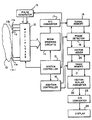
- a body 10 whose internal constituents are to be non-invasively probed by ultrasonic energy to derive a displayable image.
- ultrasonic transducing elements 11a, 11b, llc-lln shown coupled to a multiplexer 12.
- the multiplexer may be of conventional design comprising a plurality of FETtransistors or PIN diodes.
- the multiplexer may be so constructed as to provide 64 output channels that are coupled to the input of the beam steering circuits 14.
- the output channels may be so related to the input channels that each of the 64 output channels has a 1-of-3 selector.
- the transducing elements are connected to the various output channels as follows:
- each aperture or subarray In order to arrive at 64 output channels, they are arranged in overlapping fashion, e.g., the top 64, the bottom 64, and the central 64 for receiving the echo signals.
- the benefits of overlap are really not obtained. If one doubles the size of the aperture by providing two subarrays and if the benefits of overlapping are to be obtained, there must be at least three subarrays. While two subarrays operate to produce an image, such an image is not as satisfactory as those produced by three overlapping subarrays.
- each subarray effectively constitutes a small aperture relative to the total aperture of 128 elements.
- the other consideration is that increasing the number of elements increases the time required to acquire the data for processing. If the time interval is too long, it is not really a real-time system and is not commercially viable. Furthermore, the image becomes more and more susceptible to motion in various parts of the body.
- the first transmission aperture consists of transducers 17 thru 48; the second transmission aperture of elements 49 thru 80; and the third aperture of elements 81-112. Only 32 are used on transmit to obtain better focus characteristics than are achievable by using more of them. This allows the pulses in the various ones of the 32 channels to be time delayed and the multiplexer 12 can select any one of the three energized subarrays, i.e., the sets of 32 contiguous elements.
- the transmitted beam from each subarray can be steered in any direction to cause interrogation of any selected part of the scene. While some types of ultrasonic devices produce beams which are manually shifted across the body and others such as linear scanners, have a large number of transducing elements located in a row which can be successively energized by pulses, most scanners involving arrays do require beam steering. In such conventional systems, the beam formed by the emissions of a plurality of transducing elements, is moved in azimuthal fashion across a pie- shaped field of view of the scene to be insonified. In the present system, the scanning may be done as follows.
- the first subarray scans in successive intervals of time with a beam at say, -45°, -44°, etc. to +45° whereupon the next subarray duplicates the scanning sequence starting with -45°.
- first subarray could produce a beam at -45°
- second subarray could do the same thing followed by the third subarray.
- first subarray would produce a beam at -44° and second and third subarrays would do the same thing in sequence, and so on.
- the latter system is preferable in that it minimizes the effects of motion in the body.
- the beam steering circuits 14 comprise one channel of amplification for each of the channels of multiplexer 12.
- those amplifiers are followed by variable time delay circuits which may be of conventional design comprising lumped constants or charge coupled devices. They are used for delaying the analog signals received from the amplifiers and preferably (for this embodiment) should have a delay capability of up to 13 microseconds. If desired, a commercially available phased array, having a 64 channel capacity may alternatively be adapted for this purpose.
- the steering circuits 14 also include summation circuits whose composite output signal is used in producing the "focused" ultrasonic beam of a particular subarray in a particular direction. The direction of the beam can be changed between successive pulses in response to control signals applied to circuit 14 from the system controller 15.
- One of the functions of the system controller 15 is to select, by the application of appropriate control signals to the multiplexer 12, the direction of the transmitted beam and which of the 3 subarrays is to be actuated.
- This controller can be, for example, a computer.
- an analog-digital converter 17 which converts them to a digital form suitable for storage in the signal memory 18.
- the latter can be a RAM having a two megabyte capacity.
- the converter acting upon a summed analog signal there could be an analog-digital converter provided for each of the signals in the 64-channel bus coupling multiplexer 12 to beam steering circuits 14. In that case, the digital converters will provide digital signal inputs to circuits 14 so that the introduction of delay into those digital signals could be accomplished by digital means.
- each storage location in it corresponds to a known time interval after the pulse was transmitted onto the selected part of the body. Since the speed of sound in the body is fairly constant, it can be said that each storage location corresponds to a known distance into the body.
- Phase detector 19 is provided for deriving from the stored signals in signal memory 18 a vector quantity representing the phase and amplitude of the signal at a specified distance from the transmitting transducers. Whenever a selected distance is specified to it upon receipt of a range signal from addition controller 16 it produces two digital numbers on two respective output lines which correspond to the in-phase and quadrature components of the signal at that range or distance.
- the phase detector 19 can operate, for example, according to either one of two different principles, i.e. (1) select two samples from signal memory 18 which were taken at times which were T/4 apart, where T is the period of the center frequency of the signal, or (2) multiply by the sine and cosine of the center frequency over a window of several samples of signals stored in signal memory 18 and then add the components of the resultant vectors. Regardless of which method is used, its output is a pair of numbers in digital form which represent the signal at a specified range. If the precision desired is greater than the sampling rate during digitization, a complex phase-shift operation may be performed to interpolate to the closest
- phase detector 19 Another possible modification of the system would be to locate the phase detector 19 to receive the summed signal in the output of circuits 14. In that case, there would be two- analog digital converters to which the I and Q signals would be respectively supplied.
- Addition controller 16 may take the form of a large ROM having a list of all pixel addresses in image memory 21 which correspond to every possible beam angle produced by the subarrays. It is under the control of signals applied to it from system controller 15. Controller 16 determines by its address signals applied to image memory 21 which location in that memory 21 (correspond to a pixel) is accessed. To determine which pixel corresponds to a pulse of acoustic energy fired from a particular transducer subarray at a particular angle, the paths of all the pulses to be transmitted from a single subarray can be projected on to the X, Y grid of the image memory 21 and a fan-shaped pattern of rays emanates from the center of the transmitter. By so doing, it can be determined which ray is geometrically closest to the pixel location, that ray then being considered to correspond to the specified pixel.
- the in phase (I) and quadrature (Q) signals from the phase detector 19 are applied to the vector adder 20 where one vector from each subarray for one pixel at a time is to be added to the current contents of the image memory 21, the specific pixel selected being determined by address signals from the addition controller 16.
- Adder 20 operates in conventional sequence, i.e., (1) it acquires the current contents of a selected pixel- representative signal location in image memory 21, (2) obtains a new phase vector from the phase detector 19, (3) adds the I and Q components separately, and (4) applies the new vector sum back into the same pixel signal location in the image memory 21 thereby replacing its old contents in that slot.
- the addition controller 16 can be implemented in ways other than storage of the range information corresponding to each pixel. Instead, based upon the x and y coordinates and the known position of the transmitter, the range of each pixel could be computed (rather than being stored) by the system controller (CPU). Also, the capacity of the ROM can be reduced by a factor of 6 by taking advantage of the symmetrical aspects of the scene, i.e. (1) since the geometry of the three subarrays are identical, the pixels corresponding to a particular beam differ only in a constant translation of the X component, and/or (2) the left-right mirror symmetry along the center of each subarray can also be exploited.
- the image memory 21 When the image memory 21 has all of its locations filled with the vectorial-representative digital information of the updated I and Q signals, they must then be converted to scalar quantities before changing them from digital form to analog form for display on a cathode ray tube which is an analog device.
- the object of this apparatus and method is to produce a video-type display, which is of the analog signal type
- the stored pixel-representative digital numbers in the image memory 21 which correspond to vector quantities must first be converted to scalar quantities and the latter must be converted from digital to analog signals.
- the converter 22 accepts the two numbers of each memory location in memory 21 which corresponds to each pixel and derives a single number in digital form which is applied to converter 23.
- the two numbers in each memory location in memory 21 can be representative of two different amplitudes at right angles to one another or can be amplitude and phase-representative numbers. If the two numbers represent two amplitudes at right angles, the converter 22 performs the mathematical operation of squaring each of them and then taking the square root of their sum. Apparatus is well known for doing this although this could alternatively be accomplished by using a computer and appropriate software.
- the single scalar number at the output of converter 22 is applied to a conventional digital- analog converter to derive a video signal applied to a cathode ray tube for producing the image of the scene being probed.
- the various steps of insonification by each of the plurality of subarrays and the reception and processing of the reflected signals can be regarded as follows: If there are M transmitting apertures (subarrays) used in sequence and M complex images respectively corresponding to these apertures (subarrays) to be obtained. Let 1 m by the mth complex image corresponding to the mth transmitter and imn(P) and in(p) bethe complex numbers denoting the amplitude and phase of the nth frequency component in the composite time signal corresponding to the pth pixel, in the mth complex image and the final complex image, respectively. The value i n (p) is obtained by The signals corresponding to this equation A are found in signal memory 18.
- I(p) be the intensity of the pth pixel to be displayed.
- I(p) is obtained by where N is the number of the frequency components which can vary from one to any arbitrary number depending upon the system constraints and an is the weighting coefficient attached to the nth frequency component and can be varied to obtain different types of images.
- the designer of the system must initially determine how many complex number signals are required to adequately describe the original object when they are finally summed. If just one frequency component is used, there is no summation. However, if several frequency components are used, one of them is often weighted more than the others so that it can be a better match for the characteristics of the transmit pulse which has a finite time duration. It may be found preferable to weight the central frequency components more than the off-center frequency components. For purposes of reducing memory requirements, one frequency component may prove desirable.
Landscapes
- Engineering & Computer Science (AREA)
- Physics & Mathematics (AREA)
- Radar, Positioning & Navigation (AREA)
- Remote Sensing (AREA)
- Acoustics & Sound (AREA)
- Computer Networks & Wireless Communication (AREA)
- General Physics & Mathematics (AREA)
- Ultra Sonic Daignosis Equipment (AREA)
- Investigating Or Analyzing Materials By The Use Of Ultrasonic Waves (AREA)
- Measurement Of Velocity Or Position Using Acoustic Or Ultrasonic Waves (AREA)
Abstract
Claims (14)
Applications Claiming Priority (2)
| Application Number | Priority Date | Filing Date | Title |
|---|---|---|---|
| US06/574,883 US4553437A (en) | 1984-01-30 | 1984-01-30 | Hybrid non-invasive ultrasonic imaging system |
| US574883 | 1984-01-30 |
Publications (3)
| Publication Number | Publication Date |
|---|---|
| EP0179073A1 EP0179073A1 (fr) | 1986-04-30 |
| EP0179073A4 EP0179073A4 (fr) | 1986-11-25 |
| EP0179073B1 true EP0179073B1 (fr) | 1990-04-04 |
Family
ID=24298045
Family Applications (1)
| Application Number | Title | Priority Date | Filing Date |
|---|---|---|---|
| EP85900913A Expired EP0179073B1 (fr) | 1984-01-30 | 1985-01-23 | Systeme de mise en image ultrasonique hybride de non-invasion |
Country Status (6)
| Country | Link |
|---|---|
| US (1) | US4553437A (fr) |
| EP (1) | EP0179073B1 (fr) |
| JP (1) | JPH0644908B2 (fr) |
| AU (1) | AU3884885A (fr) |
| DE (1) | DE3577001D1 (fr) |
| WO (1) | WO1985003354A1 (fr) |
Families Citing this family (22)
| Publication number | Priority date | Publication date | Assignee | Title |
|---|---|---|---|---|
| JPS6070381A (ja) * | 1983-09-28 | 1985-04-22 | Toshiba Corp | 超音波映像化装置 |
| DE3525179A1 (de) * | 1985-07-15 | 1987-01-22 | Siemens Ag | Verfahren und geraet zur ultraschall-abtastung eines objekts |
| US4793184A (en) * | 1985-10-09 | 1988-12-27 | Hitachi Ltd. | Ultrasonic imaging apparatus and method of forming an ultrasonic image of an object |
| US5383457A (en) * | 1987-04-20 | 1995-01-24 | National Fertility Institute | Method and apparatus for processing images |
| US5111823A (en) * | 1989-04-20 | 1992-05-12 | National Fertility Institute | Apparatus and method for generating echographic images |
| GB2256765B (en) * | 1989-11-28 | 1994-01-05 | Marconi Gec Ltd | Synthetic aperture imaging apparatus |
| US5079951A (en) * | 1990-08-16 | 1992-01-14 | Her Majesty The Queen In Right Of Canada, As Represented By The Minister Of Agriculture | Ultrasonic carcass inspection |
| US5278757A (en) * | 1991-11-15 | 1994-01-11 | The Trustees Of The University Of Pennsylvania | Synthetic aperture ultrasonic imaging system using a minimum or reduced redundancy phased array |
| US5482044A (en) * | 1992-01-14 | 1996-01-09 | Diasonics Ultrasound, Inc. | Direct demodulation in ultrasound instruments |
| GB2268806B (en) * | 1992-07-14 | 1997-02-26 | Intravascular Res Ltd | Methods and apparatus for the examination and treatment of internal organs |
| US5355888A (en) * | 1992-11-12 | 1994-10-18 | Massachusetts Institute Of Technology | High resolution phased array echo imager |
| KR950013122B1 (ko) * | 1993-05-24 | 1995-10-25 | 주식회사메디슨 | 초음파신호의 디지탈집속방법 및 그 장치 |
| GB2293240B (en) * | 1994-09-15 | 1998-05-20 | Intravascular Res Ltd | Ultrasonic visualisation method and apparatus |
| US5460178A (en) * | 1995-01-31 | 1995-10-24 | Centre De Recherche Industrielle Du Quebec | Ultrasonic transmission imaging apparatus and method |
| US5685307A (en) * | 1995-02-28 | 1997-11-11 | Iowa State University Research Foundation, Inc. | Method and apparatus for tissue characterization of animals using ultrasound |
| US5617862A (en) * | 1995-05-02 | 1997-04-08 | Acuson Corporation | Method and apparatus for beamformer system with variable aperture |
| US6254542B1 (en) | 1995-07-17 | 2001-07-03 | Intravascular Research Limited | Ultrasonic visualization method and apparatus |
| US5951479A (en) * | 1998-09-29 | 1999-09-14 | General Electric Company | Method and apparatus for synthetic transmit aperture imaging |
| US7972271B2 (en) * | 2003-10-28 | 2011-07-05 | The Board Of Trustees Of The Leland Stanford Junior University | Apparatus and method for phased subarray imaging |
| US20050101867A1 (en) * | 2003-10-28 | 2005-05-12 | Johnson Jeremy A. | Apparatus and method for phased subarray imaging |
| US20080294050A1 (en) * | 2004-07-08 | 2008-11-27 | Ryuichi Shinomura | Ultrasonic Imaging Apparatus |
| US7925068B2 (en) * | 2007-02-01 | 2011-04-12 | General Electric Company | Method and apparatus for forming a guide image for an ultrasound image scanner |
Family Cites Families (9)
| Publication number | Priority date | Publication date | Assignee | Title |
|---|---|---|---|---|
| US3719922A (en) * | 1971-06-24 | 1973-03-06 | L Lopes | Digital camera |
| US3805596A (en) * | 1972-02-24 | 1974-04-23 | C Klahr | High resolution ultrasonic imaging scanner |
| US3931597A (en) * | 1974-02-04 | 1976-01-06 | The Magnavox Company | Apparatus and method for phase-encoded surface wave devices |
| US4206653A (en) * | 1975-10-02 | 1980-06-10 | E M I Limited | Ultrasonic apparatus |
| US4105018A (en) * | 1976-02-02 | 1978-08-08 | University Of Utah | Acoustic examination, material characterization and imaging of the internal structure of a body by measurement of the time-of-flight of acoustic energy therethrough |
| US4241608A (en) * | 1978-01-24 | 1980-12-30 | Unirad Corporation | Ultrasonic scanner |
| US4155260A (en) * | 1978-05-24 | 1979-05-22 | General Electric Company | Ultrasonic imaging system |
| US4265126A (en) * | 1979-06-15 | 1981-05-05 | General Electric Company | Measurement of true blood velocity by an ultrasound system |
| US4319489A (en) * | 1980-03-28 | 1982-03-16 | Yokogawa Electric Works, Ltd. | Ultrasonic diagnostic method and apparatus |
-
1984
- 1984-01-30 US US06/574,883 patent/US4553437A/en not_active Expired - Lifetime
-
1985
- 1985-01-23 AU AU38848/85A patent/AU3884885A/en not_active Abandoned
- 1985-01-23 EP EP85900913A patent/EP0179073B1/fr not_active Expired
- 1985-01-23 JP JP60500609A patent/JPH0644908B2/ja not_active Expired - Lifetime
- 1985-01-23 WO PCT/US1985/000116 patent/WO1985003354A1/fr not_active Ceased
- 1985-01-23 DE DE8585900913T patent/DE3577001D1/de not_active Expired - Lifetime
Also Published As
| Publication number | Publication date |
|---|---|
| DE3577001D1 (de) | 1990-05-10 |
| WO1985003354A1 (fr) | 1985-08-01 |
| JPH0644908B2 (ja) | 1994-06-15 |
| EP0179073A1 (fr) | 1986-04-30 |
| JPS61501070A (ja) | 1986-05-29 |
| EP0179073A4 (fr) | 1986-11-25 |
| AU3884885A (en) | 1985-08-09 |
| US4553437A (en) | 1985-11-19 |
Similar Documents
| Publication | Publication Date | Title |
|---|---|---|
| EP0179073B1 (fr) | Systeme de mise en image ultrasonique hybride de non-invasion | |
| EP0155280B1 (fr) | Systeme de prise d'images d'un corps utilisant l'addition vectorielle de reflexions acoustiques pour obtenir l'effet d'un faisceau de balayage focalise en continu suivant un alignement geometrique predetermine | |
| Karaman et al. | Synthetic aperture imaging for small scale systems | |
| US4817434A (en) | Device for imaging three dimensions using simultaneous multiple beam formation | |
| US7285094B2 (en) | 3D ultrasonic imaging apparatus and method | |
| US5720708A (en) | High frame rate imaging with limited diffraction beams | |
| US4159462A (en) | Ultrasonic multi-sector scanner | |
| Thurstone et al. | A new ultrasound imaging technique employing two-dimensional electronic beam steering | |
| US5951479A (en) | Method and apparatus for synthetic transmit aperture imaging | |
| EP0473959B1 (fr) | Méthode de transformation d'un image sonar à faisceaux multiples | |
| US4694434A (en) | Three-dimensional imaging system | |
| US4550607A (en) | Phased array acoustic imaging system | |
| EP0087318B1 (fr) | Dispositif pour diagnostic ultrasonore | |
| US4596145A (en) | Acoustic orthoscopic imaging system | |
| US20050148874A1 (en) | Ultrasonic imaging aberration correction with microbeamforming | |
| EP1004894B1 (fr) | Méthode et appareil d'acquisition de données d'imagerie ultrasonore à haute résolution et à fréquences de trames élevées | |
| JP4428477B2 (ja) | ビームフォーミング用時間遅延及びアポダイゼーション値の敏速な分散型計算のための方法及び装置 | |
| US5415173A (en) | Ultrasound diagnosis system | |
| GB2099582A (en) | Ultrasonic image methods and apparatus | |
| KR20000070742A (ko) | 다차원 빔형성 장치 | |
| JPH10309276A (ja) | 超音波イメージング・システムの作動方法 | |
| Gehlbach et al. | Digital ultrasound imaging techniques using vector sampling and raster line reconstruction | |
| EP0139242B1 (fr) | Appareil d'imagerie par ultra-sons | |
| US4688430A (en) | Device for imaging three dimensions with a single pulse transmission | |
| US5476098A (en) | Partially coherent imaging for large-aperture phased arrays |
Legal Events
| Date | Code | Title | Description |
|---|---|---|---|
| PUAI | Public reference made under article 153(3) epc to a published international application that has entered the european phase |
Free format text: ORIGINAL CODE: 0009012 |
|
| 17P | Request for examination filed |
Effective date: 19860121 |
|
| AK | Designated contracting states |
Kind code of ref document: A1 Designated state(s): DE FR GB NL SE |
|
| A4 | Supplementary search report drawn up and despatched |
Effective date: 19861125 |
|
| 17Q | First examination report despatched |
Effective date: 19880504 |
|
| GRAA | (expected) grant |
Free format text: ORIGINAL CODE: 0009210 |
|
| AK | Designated contracting states |
Kind code of ref document: B1 Designated state(s): DE FR GB NL SE |
|
| PG25 | Lapsed in a contracting state [announced via postgrant information from national office to epo] |
Ref country code: SE Effective date: 19900404 Ref country code: NL Effective date: 19900404 Ref country code: FR Effective date: 19900404 |
|
| REF | Corresponds to: |
Ref document number: 3577001 Country of ref document: DE Date of ref document: 19900510 |
|
| EN | Fr: translation not filed | ||
| NLV1 | Nl: lapsed or annulled due to failure to fulfill the requirements of art. 29p and 29m of the patents act | ||
| PLBE | No opposition filed within time limit |
Free format text: ORIGINAL CODE: 0009261 |
|
| STAA | Information on the status of an ep patent application or granted ep patent |
Free format text: STATUS: NO OPPOSITION FILED WITHIN TIME LIMIT |
|
| 26N | No opposition filed | ||
| PGFP | Annual fee paid to national office [announced via postgrant information from national office to epo] |
Ref country code: GB Payment date: 19990128 Year of fee payment: 15 |
|
| PGFP | Annual fee paid to national office [announced via postgrant information from national office to epo] |
Ref country code: DE Payment date: 19990201 Year of fee payment: 15 |
|
| PG25 | Lapsed in a contracting state [announced via postgrant information from national office to epo] |
Ref country code: GB Free format text: LAPSE BECAUSE OF NON-PAYMENT OF DUE FEES Effective date: 20000123 |
|
| GBPC | Gb: european patent ceased through non-payment of renewal fee |
Effective date: 20000123 |
|
| PG25 | Lapsed in a contracting state [announced via postgrant information from national office to epo] |
Ref country code: DE Free format text: LAPSE BECAUSE OF NON-PAYMENT OF DUE FEES Effective date: 20001101 |