EP0179113B1 - Dispositif de distribution de liquides tels que liquides alimentaires et notamment boissons - Google Patents
Dispositif de distribution de liquides tels que liquides alimentaires et notamment boissons Download PDFInfo
- Publication number
- EP0179113B1 EP0179113B1 EP19850902057 EP85902057A EP0179113B1 EP 0179113 B1 EP0179113 B1 EP 0179113B1 EP 19850902057 EP19850902057 EP 19850902057 EP 85902057 A EP85902057 A EP 85902057A EP 0179113 B1 EP0179113 B1 EP 0179113B1
- Authority
- EP
- European Patent Office
- Prior art keywords
- fact
- longitudinal member
- truck according
- cross
- slide
- Prior art date
- Legal status (The legal status is an assumption and is not a legal conclusion. Google has not performed a legal analysis and makes no representation as to the accuracy of the status listed.)
- Expired
Links
- 239000007788 liquid Substances 0.000 title abstract 4
- 235000013361 beverage Nutrition 0.000 title 1
- 230000000050 nutritive effect Effects 0.000 title 1
- 125000006850 spacer group Chemical group 0.000 claims description 8
- 230000000284 resting effect Effects 0.000 claims description 5
- 238000007666 vacuum forming Methods 0.000 abstract 3
- 239000012141 concentrate Substances 0.000 abstract 1
- 239000003085 diluting agent Substances 0.000 abstract 1
- 238000000265 homogenisation Methods 0.000 abstract 1
- 238000000034 method Methods 0.000 abstract 1
- 238000000151 deposition Methods 0.000 description 2
- 239000002184 metal Substances 0.000 description 2
- 101100441413 Caenorhabditis elegans cup-15 gene Proteins 0.000 description 1
- 230000008878 coupling Effects 0.000 description 1
- 238000010168 coupling process Methods 0.000 description 1
- 238000005859 coupling reaction Methods 0.000 description 1
- 238000006073 displacement reaction Methods 0.000 description 1
- 239000000463 material Substances 0.000 description 1
Images


Classifications
-
- B—PERFORMING OPERATIONS; TRANSPORTING
- B67—OPENING, CLOSING OR CLEANING BOTTLES, JARS OR SIMILAR CONTAINERS; LIQUID HANDLING
- B67D—DISPENSING, DELIVERING OR TRANSFERRING LIQUIDS, NOT OTHERWISE PROVIDED FOR
- B67D1/00—Apparatus or devices for dispensing beverages on draught
- B67D1/0042—Details of specific parts of the dispensers
- B67D1/0043—Mixing devices for liquids
- B67D1/0044—Mixing devices for liquids for mixing inside the dispensing nozzle
- B67D1/0045—Venturi arrangements; Aspirators; Eductors
-
- B—PERFORMING OPERATIONS; TRANSPORTING
- B67—OPENING, CLOSING OR CLEANING BOTTLES, JARS OR SIMILAR CONTAINERS; LIQUID HANDLING
- B67D—DISPENSING, DELIVERING OR TRANSFERRING LIQUIDS, NOT OTHERWISE PROVIDED FOR
- B67D1/00—Apparatus or devices for dispensing beverages on draught
- B67D1/0015—Apparatus or devices for dispensing beverages on draught the beverage being prepared by mixing at least two liquid components
- B67D1/0021—Apparatus or devices for dispensing beverages on draught the beverage being prepared by mixing at least two liquid components the components being mixed at the time of dispensing, i.e. post-mix dispensers
- B67D1/0022—Apparatus or devices for dispensing beverages on draught the beverage being prepared by mixing at least two liquid components the components being mixed at the time of dispensing, i.e. post-mix dispensers the apparatus comprising means for automatically controlling the amount to be dispensed
- B67D1/0027—Apparatus or devices for dispensing beverages on draught the beverage being prepared by mixing at least two liquid components the components being mixed at the time of dispensing, i.e. post-mix dispensers the apparatus comprising means for automatically controlling the amount to be dispensed control of the amount of one component, the amount of the other components(s) being dependent on that control
Definitions
- the present invention relates to a vehicle or equipment support trolley comprising a spar resting, at its ends, on two crosspieces fitted with swivel casters and supporting two adjustable support points intended to allow its easy movement in all directions.
- the object of the invention is to provide a carriage capable of adapting to the shapes and dimensions of the equipment, objects and materials resting on it, by means of adjusting its support points in length, in height. and in orientation.
- the US-A-1 patent. 341.621 describes a carriage comprising an adjustable chassis by its two side members associated with non-orientable crosspieces.
- the possibilities for adjusting the support points and the frame rails are limited to the hole spacings which allow the introduction of retaining pins.
- the prevet FR-A-2.158. 577 describes a removable bench for lift.
- the shims are adjusted on the side members using holes and pins.
- German patent DE-A-3,200,300 describes a device with two telescopic beams associated with two rigid crosspieces.
- the length and width of the support points, which are also fixed to the telescopic elements of the crosspieces, are adjusted by means of corresponding holes and pins.
- the carriage in question is characterized in that the support points of the vehicle or of the equipment are carried by two slides each comprising a guide means and a locking means on the beam and that the crosspieces to which said coupling is coupled spar are adjustable.
- the spar is a hollow profile leaving a groove in which engages a means for guiding the U-shaped slides arranged astride said beam, each slide comprising a vertical tube on which rests a removable tubular spacer supporting a screw jack constituting each fulcrum. Each slide is blocked on the spar which it overlaps by means of a screw taking nut in the spar.
- the reference 1 designates the side member of the carriage produced in a hollow metal profile, the upper face of which leaves a groove 2 limited by the folded edges 1a of said profile.
- This tongeron 1 rests, by its two ends, on two crosspieces 3 in the shape of an inverted U and whose lateral wings are cut at an angle to allow the pivoting of wheels 4 mounted in pivoting yokes 5, in known manner, fixed to each end of said sleepers 3.
- crosspieces 3 are orientable relative to the spar 1.
- a screw 6, passing through both the spar 1 and the crosspiece 3 acts as an axis capable of being tightened by means of a maneuverable nut with by hand, in order to block the cross member 3 in the 'chosen orientation position.
- a stop 7 integral with the cross member 3 it is impossible to orient the cross member 3 beyond an unstable position of the support.
- each slide 8 can be locked in the chosen position on the beam 1 by means of a screw 9 with an operating lever.
- the head of this screw is supported on the slide 8 and takes nut in a plate 10 pressing against the internal edges 1a of the beam 1.
- the operation of the screw 9 secures the slide 8 and the beam 1.
- the slide 8 can be locked in a position where it extends beyond the side member 1, thereby increasing the capacity of the assembly.
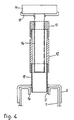
- Each slide 8 comprises a candle comprising, as illustrated in FIG. 4, a tube 11 made integral with the slide 8 which it crosses, so that its lower end penetrates into the groove 2 which the spar 1 leaves behind.
- a tubular spacer 12 On this end of tube 11 is supported by a tubular spacer 12 by the internal shoulder which it comprises.
- a nut 13 On the free and constricted end of the spacer 12, in turn is supported a nut 13 by the internal shoulder which it forms.
- the nut 13 can be carried directly by the tube 11, by depositing the spacer 12. It is also possible to envisage a set of spacers of different heights, in which the appropriate spacer is chosen.
- a threaded rod 14 surmounted by a cup 15 in which is fixed a rubber pad 16, or a gripping means adapted to the supported object.
- a particularly advantageous application of the support trolley is its use in a garage, where the vehicles have to pass from one station to another, or be stored while waiting for the spare parts.
- These difficult displacements, for vehicles which can be deprived of wheels, placed on fixed jack stands, not maneuverable for mechanical reasons, are made very easy by depositing the vehicle 17 on a trolley (FIG. 5) or two trolleys (FIG. 6) .
- the spacing adjustment is obtained by sliding the slides 8 on the side member 1 and locking them in the chosen position by means of the screws 9.
- the height of the support points 15 is adjusted by maneuvering the rod 14 or the nut 13, which makes it possible to approach the buffer 16 until it touches the chassis of the vehicle.
- the carriage comprises two longitudinal members arranged in parallel resting on two crosspieces, each longitudinal member comprising two slides.
- the pads 16, or even the cups 15 can be replaced by supports adapted to the shapes of the objects to be moved, such as metal profiles, for example, but not exclusively.
Landscapes
- Non-Alcoholic Beverages (AREA)
- Devices For Dispensing Beverages (AREA)
- Handcart (AREA)
Abstract
Description
- La présente invention a pour objet un chariot support de véhicule ou de matériel comprenent un longeron reposant, par ses extrémités, sur deux traverses équipées de roulettes pivotantes et supportant deux points d'appui réglables destiné à permettre son déplacement aisé dans toutes les directions.
- Le but de l'invention est de fournir un chariot susceptible de s'adapter aux formes et aux dimensions des matériels, des objets et des matériaux reposant sur lui, grâce à des moyens de réglage de ses points d'appui en longeur, en hauteur et en orientation.
- Le brevet US-A-1. 341.621 décrit un chariot comportant un châssis réglable par ses deux longerons associés à des traverses non orientables. Les possibilités de réglage des points d'appui et des longerons du châssis sont limitées aux espacements d'orifices qui permettent l'introduction de chevilles de retenue.
- Le prevet FR-A-2.158. 577 décrit un banc amovible pour pont élévateur. Le réglage des cales sur les longerons a lieu au moyen de trous et de goupilles.
- Le brevet allemand DE-A-3.200.300 décrit un dispositif à deux longerons télescopiques associés à deux traverses rigides. Le réglage en longueur et en largeur des points d'appui, par ailleurs fixés sur des éléments télescopique des traverses, s'effectue grâce à des orifices et des goupilles correspondantes.
- La précision de réglage de tous les moyens de guidage, d'orientation et d'appui fournis par les dispositifs antérieurs, est précaire, inconvénient auquel remédie le chariot support objet de la présente invention.
- Le chariot dont il s'agit est caractérisé par le fait que les points d'appui du véhicule ou du matériel sont portés par deux coulisseaux comportant chacun un moyen de guidage et un moyen de blocage sur le longeron et que les traverses auxquelles est accouplé ledit longeron sont orientables.
- Suivant une forme d'exécution préférentielle de l'invention, le longeron est un profilé creux laissant subsister une rainure dans laquelle s'engage un moyen de guidage des coulisseaux en forme de U disposés à cheval sur ledit longeron, chaque coulisseau comportant un tube vertical sur lequel s'appuie une entretoise tubulaire amovible supportant un vérin à vis constituant chaque point d'appui. Chaque coulisseau est bloqué sur le longeron qu'il chevauche au moyen d'une vis prenant écrou dans le longeron.
- Un exemple de réalisation du chariot support dont il s'agit est illustré par les dessins annexés sur lesquels:
- La figure 1 est une vue en élévation d'un chariot suivant l'invention.
- La figure 2 est une vue de côté
- La figure 3 est une vue en plan par-dessus.
- La figure 4 est une vue en coupe d'elévation d'un point d'appui réglable du chariot.
- Les figures 5 et 6 montrent l'utilisation du chariot pour le déplacement d'un véhicule.
- Sur les figures 1 à 4, le repère 1 désigne le longeron du chariot réalisé dans un profilé métallique creux dont la face supérieure laisse subsister une rainure 2 limitée par les bords rabattus 1a dudit profilé.
- Ce tongeron 1 repose, par ses deux extrémités, sur deux traverses 3 en forme de U renversé et dont les ailes latérales sont coupées en biais pour permettre le pivotement de roues 4 montées dans des chapes pivotantes 5, à la manière connue, fixées à chaque extrémité desdites traverses 3.
- Ces traverses 3 sont orientables par rapport au longeron 1. A cet effet, une vis 6, traversant à la fois le longeron 1 et la traverse 3, joue le rôle d'axe susceptible d'être serré au moyen d'un écrou manoeuvrable à la main, dans le but de bloquer la traverse 3 dans la' position d'orientation choisie. Toutefois, grâce à une butée 7 solidaire de la traverse 3, il est impossible d'orienter la traverse 3 au delâ d'une position d'instabilité du support.
- Sur le longeron 1 peuvent glisser deux coulisseaux 8 en forme de U à cheval sur le profilé que constitue ledit longeron. Chaque coulisseau 8 peut être bloqué dans la position choisie sur le longeron 1 au moyen d'une vis 9 à manette de manoeuvre. La tête de cette vis s'appuie sur le coulisseau 8 et prend écrou dans une plaque 10 s'appuyant contre les rebords inernes 1a du longeron 1. La manoeuvre de la vis 9 solidarise le coulisseau 8 et le longeron 1. Le coulisseau 8 peut être bloqué dans une position où il déborde du longeron 1, ce qui permet d'augmenter la capacité de l'ensemble.
- Chaque coulisseau 8 comporte une chandelle comprenant, comme l'illustre la figure 4, un tube 11 rendu solidaire du coulisseau 8 qu'il traverse, afin que son extrémité inférieure pénètre dans la rainure 2 que laisse subsister le longeron 1. Sur ce bout de tube 11 s'appuie une entretoise tubulaire 12 par l'épaulement interne qu'elle comporte. Sur l'extrémité libre et rétreinte de l'entretoise 12, s'appuie à son tour un écrou 13 par l'épaulement interne qu'il forme.
- On peut faire porter l'écrou 13 directement par le tube 11, en déposant l'entretoise 12. On peut d'ailleurs envisager un jeu d'entretoises de différentes hauteurs, dans lequel on choisit l'entretoise adéquate.
- Dans l'écrou 13 se visse une tige filetée 14 surmontée d'une coupelle 15 dans laquelle est fixé un tampon en caoutchouc 16, ou un moyen de préhension adapté à l'objet supporté.
- Comme l'illustrent les figures 5 et 6, une application particulièrement intéressante du chariot support, est son utilisation dans un garage, où les véhicules doivent passer d'un poste à l'autre, ou être rangés en attendant les pièces de rechange. Ces déplacements difficiles, pour des véhicules qui peuvent être privés de roues, posés sur des chandelles fixes, non manoeuvrables pour des raisons mécaniques, sont rendus très faciles en déposant le véhicule 17 sur un chariot (figure 5) ou deux chariots (figure 6).
- A cet effet, et lorsque le véhicule a été soulevé, il suffit de glisser un chariot (figure 5) ou deux chariots (figure 6) sous le véhicule 17, d'orienter convenablement les traverses 3 pour obtenir une bonne stabilité de l'ensemble et de régler les points d'appui 16 en écartement et en hateur, notamment pour les positionner sous les points de levage du véhicule.
- Le réglage en écartement est obtenu en faisant glisser les coulisseaux 8 sur le longeron 1 et en les bloquant dans la position choisie au moyen des vis 9.
- Le réglage en hauteur des points d'appui 15 s'effectue en manoeuvrant la tige 14 ou l'écrou 13, ce qui permet d'approcher le tampon 16 jusqu'à toucher le châssis du véhicule.
- Ensuite, il suffit de déposer le véhicule sur les points d'appui 15 avec une course minimum et un contact amorti par les tampons en caoutchouc 16.
- Lorsque le véhicule est supporté par deux chariots (figure 6) la manoeuvre des écrous 13 permet d'ajuster la hauteur pour mettre les quatre points d'appui sur un même plan.
- Selon une variante de l'invention, le chariot comprend deux longerons disposés parallèlement reposant sur deux traverses, chaque longeron comportant deux coulisseaux.
- Il va de soi que les tampons 16, voire les coupelles 15 peuvent être remplacées par des supports adaptés aux formes des objets à déplacer, tels que des profilés metalliques, par exemple, mais non exclusivement.
Claims (9)
Priority Applications (1)
| Application Number | Priority Date | Filing Date | Title |
|---|---|---|---|
| AT85902057T ATE38972T1 (de) | 1984-04-27 | 1985-04-26 | Vorrichtung zur ausgabe von fluessigkeiten wie fluessiger nahrung und insbesondere getraenken. |
Applications Claiming Priority (2)
| Application Number | Priority Date | Filing Date | Title |
|---|---|---|---|
| FR8406644A FR2563509B1 (fr) | 1984-04-27 | 1984-04-27 | Procede et dispositif de distribution de liquides tels que liquides alimentaires et notamment boissons |
| FR8406644 | 1984-04-27 |
Publications (2)
| Publication Number | Publication Date |
|---|---|
| EP0179113A1 EP0179113A1 (fr) | 1986-04-30 |
| EP0179113B1 true EP0179113B1 (fr) | 1988-11-30 |
Family
ID=9303556
Family Applications (1)
| Application Number | Title | Priority Date | Filing Date |
|---|---|---|---|
| EP19850902057 Expired EP0179113B1 (fr) | 1984-04-27 | 1985-04-26 | Dispositif de distribution de liquides tels que liquides alimentaires et notamment boissons |
Country Status (4)
| Country | Link |
|---|---|
| EP (1) | EP0179113B1 (fr) |
| DE (1) | DE3566526D1 (fr) |
| FR (1) | FR2563509B1 (fr) |
| WO (1) | WO1985005092A1 (fr) |
Families Citing this family (10)
| Publication number | Priority date | Publication date | Assignee | Title |
|---|---|---|---|---|
| US5033649A (en) * | 1990-03-19 | 1991-07-23 | Ecolab Inc. | Chemical solution dispensing and handling system |
| US5037003A (en) * | 1990-07-17 | 1991-08-06 | Scott Paper Company | Dilution station |
| DK0581876T3 (da) * | 1991-04-24 | 1995-11-13 | Ecolab Inc | System til opløsningsproportionering og sprøjtning |
| US5255820A (en) * | 1991-04-24 | 1993-10-26 | Ecolab Inc. | Apparatus for dilution of liquid products |
| US5259557A (en) * | 1991-09-25 | 1993-11-09 | Ecolab Inc. | Solution proportioner and dispensing system |
| US5344074A (en) * | 1991-09-25 | 1994-09-06 | Ecolab Inc. | Dispensing apparatus having a removable variable proportioning and metering device |
| FR2697983B1 (fr) * | 1992-11-17 | 1995-01-27 | Achat Distribution Ste Fse | Procédé et dispositif de réalisation de doses de boisson et notamment de café. |
| WO1994029011A1 (fr) * | 1993-06-10 | 1994-12-22 | Ecolab Inc. | Systeme de dilution de produit concentre |
| US5773067A (en) * | 1994-12-23 | 1998-06-30 | Societe Agricole De Produits De Base | Method for production of metered amounts of drinks, especially coffee |
| FR2775273B1 (fr) | 1998-02-23 | 2000-03-24 | Soc Agric De Prod De Base | Procede et dispositif de distribution de boissons froides |
Family Cites Families (3)
| Publication number | Priority date | Publication date | Assignee | Title |
|---|---|---|---|---|
| US2920579A (en) * | 1957-02-01 | 1960-01-12 | Dole Valve Co | Variable concentrate proportioner |
| FR1392840A (fr) * | 1964-04-02 | 1965-03-19 | Appareil distributeur de boisson à dosage réglable | |
| DE3234957A1 (de) * | 1982-09-21 | 1984-03-22 | DAGMA Deutsche Automaten- und Getränkemaschinen GmbH & Co KG, 2067 Reinfeld | Verfahren und vorrichtung zum herstellen und portionsweisen ausgeben von stillen mischgetraenken aus fruchtsirup oder konzentraten und wasser |
-
1984
- 1984-04-27 FR FR8406644A patent/FR2563509B1/fr not_active Expired
-
1985
- 1985-04-26 DE DE8585902057T patent/DE3566526D1/de not_active Expired
- 1985-04-26 WO PCT/FR1985/000098 patent/WO1985005092A1/fr not_active Ceased
- 1985-04-26 EP EP19850902057 patent/EP0179113B1/fr not_active Expired
Also Published As
| Publication number | Publication date |
|---|---|
| EP0179113A1 (fr) | 1986-04-30 |
| WO1985005092A1 (fr) | 1985-11-21 |
| FR2563509B1 (fr) | 1987-02-27 |
| FR2563509A1 (fr) | 1985-10-31 |
| DE3566526D1 (en) | 1989-01-05 |
Similar Documents
| Publication | Publication Date | Title |
|---|---|---|
| CN101362464B (zh) | 带有轮锁的推车 | |
| US2388692A (en) | Lifting truck | |
| FR2956853A1 (fr) | Dispositif de manutention pour la manipulation d'objets lourds | |
| US20110073819A1 (en) | Adjustable carriage assembly | |
| EP0179111A1 (fr) | Chariot support de vehicule ou de materiel. | |
| KR102680505B1 (ko) | 육묘상자 이송 컨베이어 프레임용 고정 및 이동장치 | |
| EP0575217B1 (fr) | Dispositif de contrÔle de la jante d'une roue de chemin de fer | |
| EP0765776B1 (fr) | Galet de guidage pour siège réglable longitudinalement | |
| EP0435872A1 (fr) | Dispositif de levage et de pivotement pour vehicules | |
| EP2969749B1 (fr) | Trein d'atterrissage d'aéronef muni d'un galet réglable | |
| JPH06340250A (ja) | ホイールバー付車体移動装置 | |
| FR2652050A1 (fr) | Dispositif de fixation d'un vehicule et de reglage de sa position sur un chassis en vue de sa reparation. | |
| EP0178998B1 (fr) | Dispositif de levage de véhicule du type "cric" | |
| WO1996022910A1 (fr) | Dispositif pour remiser des deux-roues | |
| DE1530196C3 (de) | Abstütz- und Zentriervorrichtung für eine Mittelpufferkupplung von Schienenfahrzeugen | |
| GB2271093A (en) | A carrier for mounting on a vehicle | |
| EP0636448B1 (fr) | Unité d'indexation précise d'une palette dans le référentiel d'un poste de travail | |
| CN219685282U (zh) | 一种航天零部件精密定位装置 | |
| KR200250910Y1 (ko) | 정비차량용 운반장치 | |
| EP0130264B1 (fr) | Table à hauteur réglable | |
| CN114952150A (zh) | 一种后车架焊接加工的辅助施工装置 | |
| CN219806855U (zh) | 储油缸气泡静止周转车 | |
| DE20313580U1 (de) | Einbeiniger Ständer und Fahrrad mit einem solchen Ständer | |
| CN215885025U (zh) | 一种高度及倾角可调的新型输送机 | |
| DE840355C (de) | Liegepritsche fuer Fahrzeugreparaturen |
Legal Events
| Date | Code | Title | Description |
|---|---|---|---|
| PUAI | Public reference made under article 153(3) epc to a published international application that has entered the european phase |
Free format text: ORIGINAL CODE: 0009012 |
|
| 17P | Request for examination filed |
Effective date: 19851218 |
|
| AK | Designated contracting states |
Kind code of ref document: A1 Designated state(s): AT BE CH DE GB IT LI NL |
|
| 17Q | First examination report despatched |
Effective date: 19860908 |
|
| GRAA | (expected) grant |
Free format text: ORIGINAL CODE: 0009210 |
|
| RAP3 | Party data changed (applicant data changed or rights of an application transferred) |
Owner name: SOCIETE FRANCAISE D'ACHAT ET DE DISTRIBUTION S.O.F |
|
| AK | Designated contracting states |
Kind code of ref document: B1 Designated state(s): AT BE CH DE GB IT LI NL |
|
| PG25 | Lapsed in a contracting state [announced via postgrant information from national office to epo] |
Ref country code: NL Effective date: 19881130 Ref country code: AT Effective date: 19881130 |
|
| REF | Corresponds to: |
Ref document number: 38972 Country of ref document: AT Date of ref document: 19881215 Kind code of ref document: T |
|
| REF | Corresponds to: |
Ref document number: 3566526 Country of ref document: DE Date of ref document: 19890105 |
|
| ITF | It: translation for a ep patent filed | ||
| GBT | Gb: translation of ep patent filed (gb section 77(6)(a)/1977) | ||
| NLV1 | Nl: lapsed or annulled due to failure to fulfill the requirements of art. 29p and 29m of the patents act | ||
| PLBE | No opposition filed within time limit |
Free format text: ORIGINAL CODE: 0009261 |
|
| STAA | Information on the status of an ep patent application or granted ep patent |
Free format text: STATUS: NO OPPOSITION FILED WITHIN TIME LIMIT |
|
| 26N | No opposition filed | ||
| ITTA | It: last paid annual fee | ||
| PGFP | Annual fee paid to national office [announced via postgrant information from national office to epo] |
Ref country code: GB Payment date: 19960621 Year of fee payment: 12 |
|
| PGFP | Annual fee paid to national office [announced via postgrant information from national office to epo] |
Ref country code: DE Payment date: 19960701 Year of fee payment: 12 |
|
| PGFP | Annual fee paid to national office [announced via postgrant information from national office to epo] |
Ref country code: CH Payment date: 19960715 Year of fee payment: 12 |
|
| PGFP | Annual fee paid to national office [announced via postgrant information from national office to epo] |
Ref country code: BE Payment date: 19960812 Year of fee payment: 12 |
|
| PG25 | Lapsed in a contracting state [announced via postgrant information from national office to epo] |
Ref country code: GB Effective date: 19970426 |
|
| PG25 | Lapsed in a contracting state [announced via postgrant information from national office to epo] |
Ref country code: LI Free format text: LAPSE BECAUSE OF NON-PAYMENT OF DUE FEES Effective date: 19970430 Ref country code: CH Free format text: LAPSE BECAUSE OF NON-PAYMENT OF DUE FEES Effective date: 19970430 Ref country code: BE Effective date: 19970430 |
|
| BERE | Be: lapsed |
Owner name: SOC. FRANCAISE D'ACHAT ET DE DISTRIBUTION S.O.F.A Effective date: 19970430 |
|
| REG | Reference to a national code |
Ref country code: CH Ref legal event code: PL |
|
| GBPC | Gb: european patent ceased through non-payment of renewal fee |
Effective date: 19970426 |
|
| PG25 | Lapsed in a contracting state [announced via postgrant information from national office to epo] |
Ref country code: DE Free format text: LAPSE BECAUSE OF NON-PAYMENT OF DUE FEES Effective date: 19980101 |