EP0179169B1 - Cassette de bande vidéo - Google Patents
Cassette de bande vidéo Download PDFInfo
- Publication number
- EP0179169B1 EP0179169B1 EP84306322A EP84306322A EP0179169B1 EP 0179169 B1 EP0179169 B1 EP 0179169B1 EP 84306322 A EP84306322 A EP 84306322A EP 84306322 A EP84306322 A EP 84306322A EP 0179169 B1 EP0179169 B1 EP 0179169B1
- Authority
- EP
- European Patent Office
- Prior art keywords
- housing
- lid
- tape
- spring
- reels
- Prior art date
- Legal status (The legal status is an assumption and is not a legal conclusion. Google has not performed a legal analysis and makes no representation as to the accuracy of the status listed.)
- Expired
Links
Images


Classifications
-
- G—PHYSICS
- G11—INFORMATION STORAGE
- G11B—INFORMATION STORAGE BASED ON RELATIVE MOVEMENT BETWEEN RECORD CARRIER AND TRANSDUCER
- G11B23/00—Record carriers not specific to the method of recording or reproducing; Accessories, e.g. containers, specially adapted for co-operation with the recording or reproducing apparatus ; Intermediate mediums; Apparatus or processes specially adapted for their manufacture
- G11B23/02—Containers; Storing means both adapted to cooperate with the recording or reproducing means
- G11B23/04—Magazines; Cassettes for webs or filaments
- G11B23/08—Magazines; Cassettes for webs or filaments for housing webs or filaments having two distinct ends
- G11B23/087—Magazines; Cassettes for webs or filaments for housing webs or filaments having two distinct ends using two different reels or cores
- G11B23/08707—Details
- G11B23/08721—Brakes for tapes or tape reels
-
- G—PHYSICS
- G11—INFORMATION STORAGE
- G11B—INFORMATION STORAGE BASED ON RELATIVE MOVEMENT BETWEEN RECORD CARRIER AND TRANSDUCER
- G11B23/00—Record carriers not specific to the method of recording or reproducing; Accessories, e.g. containers, specially adapted for co-operation with the recording or reproducing apparatus ; Intermediate mediums; Apparatus or processes specially adapted for their manufacture
- G11B23/02—Containers; Storing means both adapted to cooperate with the recording or reproducing means
- G11B23/04—Magazines; Cassettes for webs or filaments
- G11B23/08—Magazines; Cassettes for webs or filaments for housing webs or filaments having two distinct ends
- G11B23/087—Magazines; Cassettes for webs or filaments for housing webs or filaments having two distinct ends using two different reels or cores
- G11B23/08707—Details
- G11B23/08735—Covers
Definitions
- This invention relates generally to tape cassettes, and more particularly is directed to improvements in tape cassettes for use in recording and/or reproducing apparatus, such as, video tape recorders and the like.
- a tape cassette for use in a conventional video tape recorder (hereinafter referred to as a VTR) is provided with an opening extending along one side of the cassette housing and with a cutout in the bottom of the housing communicating with such opening.
- the magnetic tape wound on reels rotatable within the cassette housing is guided in a run extending across the opening and, when the tape cassette is loaded in a cassette holder of the VTR, tape loading pins mounted on a loading ring are inserted into the cutout of the cassette housing in back of such tape run.
- the tape loading pins engage the tape in the run between the reels, withdraw the tape from the cassette housing and wrap the withdrawn tape around the peripheral surface of a guide drum of the VTR.
- the conventional tape cassette is usually provided with a lid which is movable on the cassette housing between a closed position covering the opening of the housing and an open position to which the lid is moved when the cassette is placed in the cassette holder and in which the tape run extending across the housing opening is fully exposed.
- the lid of the foregoing conventional tape cassette when in its closed position, is intended to prevent accidental damage to the run of the tape extending across the opening of the cassette housing, such lid, even when in its closed position, only covers the outer surface of the tape run. Therefore, dust or the like may adhere to the back surface of the tape run which is exposed through the cutout in the bottom of the cassette housing even when the lid is in its closed position. As a result, dropouts may occur in the recording and reproducing of signals on the tape.
- a tape cassette comprising upper and lower housing portions assembled together to define a housing of substantially rectangular configuration having end walls and an opening along a side of said housing between said end walls, said upper and lower housing portions have substantially rectangular top and bottom walls, respectively, and flanges along the margins of said top and bottom walls engaging each other at a plane of separation substantially parallel with said top and bottom walls when said housing portions are brought together in a direction normal to said plane for defining a peripheral structure of the housing which includes said end walls, reels rotatably contained in said housing and having tape wound thereon, guide means in said housing leading said tape between said reels in a tape run extending across said opening, lid means having ears at its opposite ends with pivot pins extending across said opening, lid means having ears at its opposite ends with pivot pins extending from said ears to define a pivot axis, said lid means being mounted for movement about said pivot axis between an open position exposing said run of the tape for withdrawal from said housing and a closed position in which said lid means covers said tape run
- a latch means is mounted on said lower housing portion adjacent said one end wall of the housing and having an engaged condition for locking said lid means in said closed condition and a released condition for permitting movement of said lid means to said open position; one of said leg portions of the coil spring means engages said latch means upon the bringing together of said housing portions in said direction normal to the plane of separation for thereafter urging said latch means to said engaged condition thereof.
- said reels are disposed side-by-side in said housing and have flanges with toothed peripheries; and said braking means includes a brake body, brake guide means in said housing at a location between said reels adjacent the side of the housing remote from said side along which said opening extends, said brake body being slidable along said brake guide means between said engaged and disengaged positions, and pair of diverging, blade-like extensions projecting from said brake body toward said reels and being engageable with said toothed peripheries of the respective flanges in said engaged position for preventing rotation of said reels in the directions causing slack to appear in said tape run.
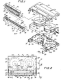
- the cassette 10 generally comprises a substantially rectangular cassette housing 11 composed of upper and lower housing portions 11 a and 11B, a pair of reels 12A and 12B rotatably contained in housing 11 in side-by-side relation and having magnetic tape 13 wound on the reels, and a lid assembly 14 composed of an outer lid member 15 and an inner lid member 16 and being pivotally mounted on housing 11 for movement between open and closed positions.
- a run 13' of the tape between reels 12A and 12B is exposed for withdrawal from housing 11, and, in the closed position shown in full lines on Fig. 4, lid assembly 14 covers or encloses tape run 13' both at the back and front of the latter.
- the upper and lower housing portions 11A and 11 B are shown to have substantially rectangular top and bottom walls 17A and 17B, respectively, and flanges 18A and 18B extend along the margins of top and bottom walls 17A and 17B, respectively, and engage each other at a plane of separation, substantially parallel with walls 17A and 17B when housing portions 11a and 11B are brought together vertically, that is, in a direction normal to the plane of separation for defining a peripheral structure of the housing which includes end walls 19 and 20 at the opposite relatively short ends of housing 11 and a back or side wall 21 along one of the relatively long sides of the rectangular housing (Fig. 2).
- bottom wall 17B has an approximately trapezoidal cutout 23 communicating with opening 22 at the front of the housing.
- the width of cutout 23 is smaller than that of opening 22, that is, the ends of cutout 23 are spaced inwardly from end walls 19 and 20.
- a substantially rectangular cutout 24 which is approximately as wide as cutout 23 is formed in the forward portion of top wall 17A and has a depth smaller than the depth of cutout 23 measured at the middle of housing 11.
- a flange 25A with curving portions depends from top wall 17A in back of cutout 24 and mates with a flange 25B having similarly curving portions directed upwardly from bottom wall 17B along the back edge of cutout 23.
- flanges 25A and 25B mate to define a partition 25 (Fig. 4) by which a space 26 containing reels 12A and 12B within housing 11 is isolated from opening 22 and cutout 23.
- housing portion 11 B is formed or molded with upstanding walls 27 and 28 (Fig. 1) directed forwardly from the opposite ends of flange 25B and being higher than the latter so as to extend from bottom wall 17B to top wall 17A in the assembled cassette.
- the outwardly directed surfaces of walls 27 and 28 which are spaced from end walls 19 and 20 are formed with rounded or semi-cylindrical surface portions 29 and 30 acting as tape guides at the opposite ends of opening 22.
- Bottom wall 17B has laterally spaced apart circular apertures 31A and 31 B in which hubs of reels 12A and 12B, respectively, are loosely received for rotatably locating the reels in space 26, and through which drive shafts or spindles (not shown) of a VTR can conventionally engage hubs of reels 12A and 12B when cassette 10 is operatively positioned in the VTR.
- the tape extending between reels 12A and 12B is directed forwardly from the reels and about guides 29 and 30 so as to establish the tape run 13' extending across opening 22.
- Walls 27 and 28 are further shown to have curving guide grooves 32 extending approximately vertically in their inwardly directed surfaces and being operative, as hereinafter described in detail, for controlling pivoting movements of inner lid member 16 relative to outer lid member 15 during the movements of the latter between the open and closed positions of lid assembly 14.
- Outer lid member 15 is shown to have a front wall portion 33 which is laterally elongated to have a length substantially equal to the distance between end walls 19 and 20 of housing 11, a shallow top wall portion 34 extending from the upper edge of front wall portion 33 and having a width smaller than the depth of cutout 24 in top wall 17A so as to be engageable over depressed, shelf-like extensions 35 of top wall 17A at the opposite ends of cutout 24, and ears 36 and 37 directed rearwardly from the opposite ends of front and top wall portions 33 and 34 and having inwardly directed pivot pins or trunnions 38 and 39, respectively, for pivotally mounting outer lid member 15 on end walls 19 and 20, as hereinafter described in detail.
- outer lid member 15 When thus pivotally connected with housing 11, outer lid member 15, in its closed position shown in full lines on Figs. 3 and 4, has wall portion 33 covering the front surface of tape run 13', while top wall portion 34 of lid member 15 extends over the tape run. However, in such closed position of outer lid member 15, the back edge of top wall portion 34 thereof is spaced substantially from the longitudinal edge of top wall 17A along cutout 24 so as to leave a gap therebetween which is to be filled or closed by inner lid member 16.
- Inner lid member 16 has a length substantially equal to that of cutout 24 and includes an elongated head portion 40 dimensioned to span the gap between the longitudinal edge of cutout 24 and the top wall portion 34 of outer lid member 15 in the closed position of the latter, and an angled skirt portion 41 extending generally downwardly and forwardly from head portion 40 along the length of the latter. As shown particularly on Fig.
- skirt portion 41 of inner lid member 16 is dimensioned so that, when lid assembly 14 is in its closed position shown in full lines with head portion 40 spanning and closing the gap between the longitudinal edge of cutout 24 and top wall portion 34 of outer lid member 15, skirt portion 41 extends downwardly in back of tape run 13' with the lower edge part 41A of skirt portion 41 substantially abutting the lower edge portion of front wall portion 33 under tape run 13'.
- tape run 13' is substantially enclosed and protected within a space defined between lid members 15 and 16 in the closed position of assembly 14 and there is no possibility of dust accumulating on, or other injurious contact with the back surface of tape run 13' through cutout 23.
- Mounting lugs 42 and 43 are desirably molded integrally with top wall portion 34 of outer lid member 15 at laterally spaced locations corresponding to the ends of inner lid member 16, and are formed with holes 44 and 45 for pivotally receiving aligned pins 46 and 47 (Fig. 1) extending from opposite ends of an intermediate part 41 B of skirt portion 41.
- Lug members 42 and 43 are desirably laterally resilient, while the end surfaces of pivot pins 46 and 47 are oblique or slanted to permit such pivot pins to be snapped into the respective holes 44 and 45 of the mounting lugs.
- inner lid member 16 Upon engagement of pins 46 and 47 in the holes of lugs 42 and 43, inner lid member 16 is mounted on outer lid member 15 for pivotal movement in respect to the latter between the previously described closed position of lid assembly 14, in which the lower edge part 41A of skirt portion 41 substantially engages against the lower edge of front wall portion 33 for enclosing and protecting tape run 13' between lid members 15 and 16, and the position shown in dot-dash lines on Fig. 4 which corresponds to the open position 14' of the lid assembly and which has the various parts of the latter identified by the previously mentioned reference numerals but with primes affixed thereto.
- Such movements of inner lid member 16 relative to outer lid member 15 are effected in response to pivotal movements of outer lid member 15 relative to housing 11 by means of follower pins 48 which are directed outwardly from arms 49 at the opposite ends of the free edge part 41A of skirt portion 41 and which are slidably engageable in the cam or guide grooves 32 in end walls 27 and 28.
- the illustrated shape of each of the cam or guide grooves 32 is selected to ensure that lower edge part 41A of skirt portion 41 comes close to the lower edge of front wall portion 33 only when lid assembly 14 is approximately at its fully closed position for avoiding any contact of the lid assembly with tape run 13' during movements between the open and closed positions of the lid assembly even if there is some slack in tape run 13'.
- cam or guide grooves 32 are shaped to ensure that, in the open position of the lid assembly indicated at 14' on Fig. 4, wall portions 33' and 34' of outer lid member 15' and the entire inner lid member 16' are disposed above the plane of top wall 17A.
- the space 50 between tape run 13' and partition 25 is completely open or free or any of portions of the lid assembly that might otherwise interfere with, or limit the upward insertion of tape loading pins through cutout 23.
- the intermediate part 41B of skirt portion 41 is desirably angled or bent toward the axis defined by pivot pins 47 and 48, as shown, so that a forwardly opening recess 51 is defined between head portion 40 and the upper part of skirt portion 41 for the reception of top wall portion 34 of outer lid member 15 when the lid assembly is in its open position indicated at 14' on Fig. 4.
- head portion 40' of inner lid member 16' forms a smooth inclined extension from front wall portion 33' of outer lid member 15.
- skirt portion 41 of inner lid member 16 is preferably formed with a rib 52 which, along with angled part 41B imparts substantial rigidity to skirt portion 41 even though the latter may be desirably molded with relatively thin wall sections.
- substantial rigidity if a user of cassette 10 extends a finger through cutout 23 and presses against skirt portion 41 in the direction of the arrow 53 on Fig. 4, such pressure will not readily bend or flex the skirt portion in a manner to withdraw pivot pins 46 and 47 from holes 44 and 45 in mounting lugs 42 and 43.
- portions 54A and 54B of flanges 18A and 18B which define the forward parts of end walls 19 and 20 are inwardly offset or recessed to accommodate ears 36 and 37 of outer lid member 15.
- Such recessed flange parts 54A at the opposite ends of upper housing portion 11 a are formed with downwardly opening cutouts 55 and 56 (Figs. 3-5) which are shaped to receive and act as pivot seats for pivot pins or trunnions 38 and 39, respectively, formed on ears 36 and 37.
- tape cassette 10 is further shown to include a coil spring 57 which is particularly shown on Figs. 3, 5 and 6 to include a coil portion 58 and angularly displaced leg portions 59 and 60 extending normally in substantially opposed directions from coil portion 58 which resiliently resists angular displacement of such leg portions relative to each other.
- a coil spring 57 is associated with pivot pin 38, as hereinafter described in detail, it will be appreciated that a similar coil spring could also be associated with the other pivot pin 39.
- coil portion 58 of coil spring 57 is disposed on pivot pin 38 extending from the inner surface of ear 36, and leg portion 59, which desirably has a downwardly bent end 59a, is engaged with a spring anchor 61 which extends inwardly from ear 36 between pivot pin 38 and front wall portion 33 of lid member 15.
- Spring anchor 61 desirably has a notch or recess 61a in its upper surface adjacent the inner surface of ear 36 so that leg portion 59 can be engaged in such notch or recess 61a for resisting inward removal of coil portion 58 from pivot pin 38.
- the other leg portion 60 of coil spring 57 is initially or tentatively engaged with a second spring anchor 62 extending inwardly from ear 36 in back of pivot pin 38, that is, at a location approximately diammetrically opposed from that of the first spring anchor 61.
- the spring anchor 62 also desirably has a notch or recess 62a in its upper end surface adjacent ear 36 for receiving leg portion 60 when initially engaged by the latter, and thereby further preventing inadvertent separation of coil spring 57 from ear 36 during the assembling of lid assembly 14 in respect to housing 11.
- spring 57 is shaped so that, when coil portion 58 is disposed on pivot pin, 38 and leg portions 59 and 60 bear against anchors 61 and 62, such leg portions 59 and 60 are resiliently urged by coil portion 58 in the directions of the arrows a on Fig. 5, that is, in the directions for retaining leg portions 59 and 60 in notches 61a and 62a.
- at least the notch 62a in anchor 62 has a lateral dimension substantially larger than the diameter of the spring wire forming coil spring 57 so that leg portion 60 is free to move laterally within notch 62a.
- lid assembly 14 is first associated with upper housing portion 11 a by inserting pivot pins 38 and 39 vertically upward in recesses or seats 55 and 56, respectively. Then, leg portion 60 of coil spring 57 is manually displaced upwardly in the direction of the arrow b on Fig. 6 so as to be moved out of notch 62a and into engagement with a third spring anchor 63 formed on the inwardly offset or recessed flange part 54A which eventually forms part of end wall 19. More particularly, and as shown on Fig. 5, spring anchor 63 has an oblique or inclined under surface portion 63a and a horizontal top surface 63b so that, during the manual movement of leg portion 60 of the spring in the direction of the arrow b on Fig.
- leg portion 60 is deflected laterally by oblique surface portion 63a and then snaps back to engage on top of surface 63b.
- the effect of coil spring 57 is to securely hold pivot pins 38 and 39 in seats or notches 55 and 56, respectively, and further to hold outer lid member 15 in its closed position with its top wall portion 34 bearing downwardly on shelf-like forward extensions 35 of upper housing portion 11A.
- the tape cassette 10 is further shown to include a latch element 64 mounted adjacent end wall 19 of housing 11 and having an engaged condition shown in full lines on Fig. 3 for locking lid assembly 14 in its closed position and a released or disengaged condition shown in dot-dash lines on Fig. 3 for permitting movement of the lid assembly to its open position.
- the coil spring 57 provided for urging lid assembly 14 to its closed position also acts on latch element 64, when housing portions 11a and 11B are assembled together, for urging latch element 64 to the engaged condition thereof. More particularly, as shown on Fig.
- latch element 64 which may be suitably molded of a synthetic resin, includes an elongated body 65 with trunnions or pivot pins 66 projecting from the opposite sides of its upper end and an actuating lug 67 projecting laterally outward from the lower end of body 65.
- Latch element 64 is received in a forwardly opening space 68 defined between offset flange part 54B of end wall 19 and an adjacent extension 69 of flange 18B, with trunnions 66 being turnable in substantially semi-circular, upwardly opening seats 70 formed in the upper edges of flange part 54B and flange extension 69.
- latch element 64 pivotally depends in space 68 with lug 67 projecting outwardly through a cutout 69a at the bottom of flange extension 69.
- the upper end of body 65 further has a rounded abutment or node 71 projecting upwardly therefrom above pivot pins or trunnions 66 and being spaced rearwardly from the latter.
- abutment or node 71 of latch element 64 extends substantially above the normal or horizontal surface 63b of spring anchor 63 so that leg portion 60 of coil spring 57 extending back of anchor 63 is engaged with node 71 and lifted from surface 63b of anchor 63 so as to urge latch element 64 to pivot in the clockwise direction, as viewed on Fig. 3, about the axis defined by the engagement of trunnions 66 in seats 70.
- spring anchor 62 which tentatively or initially engages leg portion 60 of coil spring 57 during the mounting of lid assembly 14 on upper housing portion 11A, as described above, also functions as a keeper engageable by latch element 64 in the engaged condition of the latter for holding lid assembly 14 in its closed position. More specifically, in the closed position of lid assembly 14, an upper front surface portion 72 of body 65 is engageable against anchor or keeper element 62, as shown in full lines on Fig. 3, for limiting the pivoting of latch element 64 in the clockwise direction under the urging of leg portion 60 of spring 57.
- a latch nose 73 defined by a forwardly protruding lower portion of body 65 separated from surface 72 by an undercut 74 is engageable by a lower end edge 75 of anchor 62 as shown in full lines on Fig. 3, for locking lid assembly 14 in its closed position.
- a latch release member 76 having an oblique upper end edge is suitably displaced upwardly to the position shown in dot-dash lines on Fig. 3, or otherwise acts upon lug 67 for angularly displacing latch element 64 to its released condition shown in dot-dash lines, and in which nose 73 is retracted or withdrawn from surface 75 and out of the path of travel of anchor 62.
- outer lid member 15 is released or freed for angular movement in the direction of the arrow c on Fig. 3 from its closed position shown in full lines to its open position indicated at 15'.
- lid member 15 may be effected by a suitably operated lid opener 77 which is engageable from below with lid member 15 and is moved in the direction of the arrow c after release or disengagement of latch element 64 from spring anchor or keeper 62.
- lid opener 77 By reason of the engagement of follower pins 48 in cam grooves 32, in the course of the pivotal movement of outer lid member 15 from its closed position to its open position, inner lid member 16 is pivoted relative to outer lid member 15 and is transported with the latter from the position shown in full lines to the position shown in dot-dash lines on Fig. 4.
- a curved upper end surface 78 on anchor or keeper 62 engages nose 73 of latch element 64 so as to smoothly displace the nose 73 out of the path of travel of keeper 62 until lid member 15 has returned to its closed position and nose 73 can again engage against end edge surface 75 for locking the lid assembly in its closed position.
- latch element 64 is simply placed in spaced 68 with its trunnions 66 engaging in seats 70 of lower housing portion 11 B, as shown on Fig. 6, and then the upper housing portion 11A and the lower housing portion 11B are brought vertically together, as indicated by the arrow e.
- leg portion 60 of spring 57 is automatically engaged with node 71 on latch element 64 so as to raise leg portion 60 of the spring from anchor 63 and further to ensure that latch element 64 is urged to its engaged condition.
- coil spring 57 is securely associated with lid assembly 14 during the mounting of the latter on upper housing portion 11A, and that the coil spring 57, after transfer of its leg portion 60 from engagement with anchor 62 into engagement with anchor 63, is automatically positioned for engagement with node 72 on latch element 64 in response to bringing together of housing portions 11a a and 11B in the vertical direction of arrow e.
- spring 57 which is intended to perform the dual functions of urging lid assembly 14 to its closed position and of urging latch element 64 to its engaged condition, presents no impediment to the easy, and even automatic assembling of the housing portions.
- the tape cassette 10 further includes a brake assembly 80 for preventing turning of reels 12A and 12B in the directions fand g (Fig. 9) producing slack in the tape run 13' when cassette 10 is not in use.
- brake assembly 80 is capable of being installed in housing 11 in the vertical direction, that is, in the direction e (Fig. 13) normal to the plane of separation between housing portions 11A and IID, whereby to further facilitate assembling of cassette 10.
- brake assembly 80 generally includes a brake body 81, a brake guide structure 82 in housing 11 at a location between reels 12A and 12B adjacent the side of the housing remote from opening 22 and being operative to guide brake body 81 in the fore and aft direction, that is, in a direction parallel to the plane of separation of housing portions 11A and 11 B, between engaged and disengaged positions, a pair of diverging, resilient blade-like extensions 83A and 83B projecting from brake body 81 toward reels 12A and 12B, respectively, and being engageable with toothed peripheries 84A and 84B provided on lower flanges 85A and 85B of reels 12A and 12B, respectively, and a plate spring member 86 which is also installed in housing 11 in the direction normal to the plane of separation of housing portions 11A and 11B for urging brake body 81 to its engaged position.
- guide structure 82 is formed or molded in lower housing portion 11B so as to have forwardly converging, curving side portions 87A and 87B directed upwardly from bottom wall 17B and extending from laterally spaced locations on flange 18B at the back of the cassette housing.
- the curving side portions 87A and 87B of the guide structure are substantially concentric with reels 12A and 12B and are spaced apart, at their forward ends, by a distance smaller than the maximum width of brake body 81.
- Guide structure 82 further has parallel guide walls 88a and 88b spaced apart laterally so as to be adapted to slidably guide brake body 81 therebetween for to and fro movements in the directions of the arrow h and i on Fig. 9.
- the back ends 89A and 89B of parallel guide walls 88A and 88B are spaced from flange 18B at the back of housing portion 11B and have bevelled or inclined upper corners 89'A and 89'B, as particularly shown on Fig. 11.
- guide wall 88A has a cutout 90 in its back end portion.
- Bottom wall 17B of housing portion 11B desirably has a recess 91 in its upper surface in the region of guide structure 82, and an opening 92 which is substantially laterally centered within recess 91.
- Spring locating ribs 93A and 93B are directed forwardly at laterally spaced locations on flange 18B at the back of the cassette housing so as to be located laterally outward in respect to guide walls 88A and 88B, respectively, as most clearly shown on Fig. 11.
- Such spring locating ribs 93A and 93B have oblique corners 93'A and 93'B at their upper ends and are dimensioned to extend forwardly from flange 18B a distance / 1 (Fig. 9) which is only slightly smaller than the distance / 2 from the back ends 89A and 89B of guide walls 88A and 88B to the back portion of flange 18B.
- brake body 81 has parallel side surfaces 94A and 94B spaced apart by a distance substantially equal to the distance between guide walls 88A and 88B so that the latter will slidably guide body 81 during its movements in the directions of the arrows h and i on Fig. 9.
- body 81 At its forward end, body 81 has oblique or angled corners 95A and 95B so thatthe front face 96 of body 81 has a width smaller than the distance between the forward ends of curving side portions 87A and 87B of the guide structure, as is particularly apparent on Figs. 9 and 12.
- the resilient blade-like extensions 83A and 83B normally diverge from the opposite side margins of front face 96 so that, when brake body 81 is in its engaged position with oblique corners 95A and 95B bearing against the forward end portions of curving side portions 87A and 87B, as shown in full lines on Fig. 9, blade-like extensions 83A and 83B extend at angles into engagement with peripheral teeth 84A and 84B for preventing turning of reels 12A and 12B in the directions of the arrow f and g, respectively.
- reels 12A and 12B can be turned in directions opposed to the arrows f and g, respectively, for example, for tightening the tape in the run 13', and blade-like extensions 83A and 83B then skip over the peripheral teeth of the respective reels.
- body 81 is moved in the direction of the arrow i to its disengaged position shown in dot-dash lines on Fig.
- the normally diverging blade-like extensions 83A and 83B are flexed by engagement with the forward ends of curving side portions 87A and 87B into substantially parallel relation to each other so as to surely disengage the forward ends of blade-like extensions 83A and 83B from the toothed peripheries of reels 12A and 12B.
- blade-like extensions 83A and 83B can extend above and below the respective toothed peripheries 84A and 84B of reels 12A and 12B for ensuring reliable braking of the reels when body 81 is in its engaged position.
- brake body 81 has a downwardly opening socket 97 therein which registers with opening 92 in bottom wall 17&.
- a brake releasing member 98 of the latter is extended upwardly through opening 92 into socket 97 and is displaceable rearwardly to the'position shown in dot-dash lines at 98' on Fig. 10 for moving brake body 81 to its disengaged or released position.
- the back end of brake body 81 is shown to have a sloping or inclined upper surface portion 99, an intermediate surface portion 100 that is vertical or perpendicular to the bottom surface of body 81, and a lower projecting ledge 101 (Figs. 10 and 11).
- the foregoing configuration at the back end of brake body 81 is provided for facilitating the installation of spring member 86 by which brake body 81 is normally urged to its engaged position.
- spring member 86 is desirably in the form of a plate spring formed of resilient sheet metal and includes an elongated base portion 102 with rearwardly bent end portions 103A and 103B, and a laterally directed tongue 104 struck forwardly from base portion 102 so as to be normally at a substantial angle to the latter, with such tongue 104 having a rounded end portion 105 for bearing against brake body 81.
- brake body 81 When assembling tape cassette 10, brake body 81 is inserted vertically downward between parallel guide walls 88A and 88B of guide structure 82 and is disposed in its foremost or engaged position shown on Fig. 13. Then plate spring member 86 is moved vertically downward in back of brake body 81 from the position shown in full lines on Fig. 13 through the successive positions indicated in dot-dash lines.
- the oblique or angled corners 93'A and 93'B at the upper ends of locating ribs 93A and 93B and the oblique or angled corners 89'A and 89'B at the upper ends of back end edges 89A and 89B facilitate the downward movement of base portion 102 of spring member 86 to its eventual or desired position between locating ribs 93A and 93B and the back end edges of guide walls 88A and 88B.
- tongue portion 104 yieldably urges brake body 81 forwardly, that is, in the direction of the arrow h on Fig. 9, to the operative position of the brake body.
- its tongue portion 104 is disposed above ledge 101 at the bottom of the back end of brake body 81 and thereby resists upward removal of brake body 81 from between guide walls 88A and 88B.
- leaf springs 106A and 106B may be suitably secured to the underside of top wall 17A for holding reels 12A and 12B, respectively, against bottom wall 17B when cassette 10 is not in use.
Landscapes
- Packaging Of Annular Or Rod-Shaped Articles, Wearing Apparel, Cassettes, Or The Like (AREA)
- Automatic Tape Cassette Changers (AREA)
Claims (8)
Priority Applications (8)
| Application Number | Priority Date | Filing Date | Title |
|---|---|---|---|
| CA000462948A CA1233248A (fr) | 1984-09-14 | 1984-09-12 | Cassette a bande magnetoscopique |
| EP84306322A EP0179169B1 (fr) | 1984-09-14 | 1984-09-14 | Cassette de bande vidéo |
| AT84306322T ATE43741T1 (de) | 1984-09-14 | 1984-09-14 | Videobandkassette. |
| DE8484306322T DE3478529D1 (en) | 1984-09-14 | 1984-09-14 | Video tape cassette |
| US06/651,452 US4633355A (en) | 1984-09-14 | 1984-09-17 | Video tape cassette with easy assembly of its lid and reel brakes |
| AU33094/84A AU571007B2 (en) | 1984-09-14 | 1984-09-17 | Video cassette means of assembly |
| SG515/92A SG51592G (en) | 1984-09-14 | 1992-05-07 | Video tape cassette |
| HK515/92A HK51592A (en) | 1984-09-14 | 1992-07-16 | Video tape cassette |
Applications Claiming Priority (1)
| Application Number | Priority Date | Filing Date | Title |
|---|---|---|---|
| EP84306322A EP0179169B1 (fr) | 1984-09-14 | 1984-09-14 | Cassette de bande vidéo |
Publications (2)
| Publication Number | Publication Date |
|---|---|
| EP0179169A1 EP0179169A1 (fr) | 1986-04-30 |
| EP0179169B1 true EP0179169B1 (fr) | 1989-05-31 |
Family
ID=8192760
Family Applications (1)
| Application Number | Title | Priority Date | Filing Date |
|---|---|---|---|
| EP84306322A Expired EP0179169B1 (fr) | 1984-09-14 | 1984-09-14 | Cassette de bande vidéo |
Country Status (8)
| Country | Link |
|---|---|
| US (1) | US4633355A (fr) |
| EP (1) | EP0179169B1 (fr) |
| AT (1) | ATE43741T1 (fr) |
| AU (1) | AU571007B2 (fr) |
| CA (1) | CA1233248A (fr) |
| DE (1) | DE3478529D1 (fr) |
| HK (1) | HK51592A (fr) |
| SG (1) | SG51592G (fr) |
Families Citing this family (22)
| Publication number | Priority date | Publication date | Assignee | Title |
|---|---|---|---|---|
| JPS6273379U (fr) * | 1985-10-29 | 1987-05-11 | ||
| CA1316894C (fr) * | 1986-07-18 | 1993-04-27 | Yuji Iwahashi | Dispositif d'arret pour bobine de cassette a ruban magnetique |
| US5255144A (en) * | 1986-07-18 | 1993-10-19 | Sony Corporation | Brake device for tape reel in magnetic tape cassette |
| US4739949A (en) * | 1986-10-20 | 1988-04-26 | Lin Long Jin | Wheel locks for video tape cassettes |
| IT1204520B (it) * | 1987-04-10 | 1989-03-03 | Atb Spa | Struttura di elemento elastico per l'arpionismo di trattenimento delle bobine in cassette di nastro magnetico |
| JPH0521734Y2 (fr) * | 1987-06-18 | 1993-06-03 | ||
| JP2600215B2 (ja) * | 1987-11-11 | 1997-04-16 | ソニー株式会社 | テープカセット |
| JPH01107078U (fr) * | 1987-12-29 | 1989-07-19 | ||
| JP2600264B2 (ja) * | 1988-03-31 | 1997-04-16 | ソニー株式会社 | テープリールの回転防止装置 |
| US5084799A (en) * | 1988-12-06 | 1992-01-28 | Skc Limited | Lid locking device for tape cassette |
| US5873538A (en) * | 1989-04-21 | 1999-02-23 | Tdk Corporation | Magnetic tape cassette |
| US5026000A (en) * | 1989-08-04 | 1991-06-25 | Shape Inc. | Video cassette integral dust door latch/spring |
| US5169088A (en) * | 1989-08-04 | 1992-12-08 | Shape, Inc. | Video cassette combined dust door and dust door latch spring |
| US5056735A (en) * | 1989-08-04 | 1991-10-15 | Shape Inc. | Video cassette integral actuator/reel lock/spring |
| US5316234A (en) * | 1991-05-29 | 1994-05-31 | Matsushita Electric Industrial Co., Ltd. | Tape cassette for cassette recording/reproducing apparatus |
| EP0773547B1 (fr) * | 1990-11-30 | 1999-06-23 | Matsushita Electric Industrial Co., Ltd. | Cassette à bande |
| US5449124A (en) * | 1992-11-19 | 1995-09-12 | Sony Corporation | Reel lock mechanism for tape cassette |
| JPH11185428A (ja) * | 1997-12-19 | 1999-07-09 | Fuji Photo Film Co Ltd | 磁気テープカセット |
| US6446896B1 (en) * | 1998-11-19 | 2002-09-10 | Tdk Corporation | Tape cassette |
| US6956717B2 (en) * | 2001-04-17 | 2005-10-18 | Fuji Photo Film Co., Ltd. | Recording media cartridge |
| KR100768920B1 (ko) | 2005-12-19 | 2007-10-19 | 삼성전자주식회사 | Dvd 캠코더의 하우징 개폐장치 |
| JP2007265541A (ja) * | 2006-03-29 | 2007-10-11 | Tdk Corp | 情報媒体 |
Family Cites Families (9)
| Publication number | Priority date | Publication date | Assignee | Title |
|---|---|---|---|---|
| US4239373A (en) * | 1978-11-01 | 1980-12-16 | Xerox Corporation | Full wave rectification apparatus for operation of DC corotrons |
| JPS57210489A (en) * | 1981-06-22 | 1982-12-24 | Sony Corp | Tape cassette |
| JPS58128069A (ja) * | 1982-01-25 | 1983-07-30 | Sony Corp | テ−プカセツト |
| DE3365072D1 (en) * | 1982-03-23 | 1986-09-11 | Matsushita Electric Industrial Co Ltd | Tape cassette |
| JPS593759A (ja) * | 1982-06-30 | 1984-01-10 | Hitachi Ltd | 磁気テ−プカ−トリツジの蓋ロツク機構 |
| NL8203219A (nl) * | 1982-08-17 | 1984-03-16 | Philips Nv | Magneetbandcassete. |
| JPS5982379U (ja) * | 1982-11-20 | 1984-06-04 | 日立マクセル株式会社 | テ−プカ−トリツジ |
| JPS5992478U (ja) * | 1982-12-14 | 1984-06-22 | 日立マクセル株式会社 | テ−プカ−トリツジ |
| JPS605485A (ja) * | 1983-06-22 | 1985-01-12 | Hitachi Maxell Ltd | テ−プカ−トリツジ |
-
1984
- 1984-09-12 CA CA000462948A patent/CA1233248A/fr not_active Expired
- 1984-09-14 AT AT84306322T patent/ATE43741T1/de not_active IP Right Cessation
- 1984-09-14 EP EP84306322A patent/EP0179169B1/fr not_active Expired
- 1984-09-14 DE DE8484306322T patent/DE3478529D1/de not_active Expired
- 1984-09-17 US US06/651,452 patent/US4633355A/en not_active Expired - Lifetime
- 1984-09-17 AU AU33094/84A patent/AU571007B2/en not_active Expired
-
1992
- 1992-05-07 SG SG515/92A patent/SG51592G/en unknown
- 1992-07-16 HK HK515/92A patent/HK51592A/en not_active IP Right Cessation
Also Published As
| Publication number | Publication date |
|---|---|
| ATE43741T1 (de) | 1989-06-15 |
| AU3309484A (en) | 1986-03-27 |
| AU571007B2 (en) | 1988-03-31 |
| EP0179169A1 (fr) | 1986-04-30 |
| DE3478529D1 (en) | 1989-07-06 |
| SG51592G (en) | 1992-07-24 |
| CA1233248A (fr) | 1988-02-23 |
| HK51592A (en) | 1992-07-24 |
| US4633355A (en) | 1986-12-30 |
Similar Documents
| Publication | Publication Date | Title |
|---|---|---|
| EP0179169B1 (fr) | Cassette de bande vidéo | |
| US4881137A (en) | Magnetic tape cassette with tape protective closure and lock mechanism | |
| CA1132959A (fr) | Cassette de bande magnetique | |
| JPH0572035B2 (fr) | ||
| EP0109682B1 (fr) | Cassette à bande d'enregistrement | |
| EP0406943A1 (fr) | Système d'enregistrement/reproduction de signaux sur/de bande magnétique, et appareil et cassette à utiliser dans ce système | |
| US4683510A (en) | Lock mechanism for tape protective closure for magnetic tape cassette | |
| EP0189324A2 (fr) | Compartiment de cassette dans un appareil d'enregistrement et de reproduction pour cassettes à bande magnétique | |
| JPH03242887A (ja) | テープカセット | |
| US5596464A (en) | Locking assembly for a lid member of a tape cassette | |
| US4663688A (en) | Magnetic tape cassette with improved spring member | |
| EP0169514A2 (fr) | Cassette à bande magnétique avec mécanisme de blocage des bobines | |
| JPH0325353Y2 (fr) | ||
| JPS6212103Y2 (fr) | ||
| US6286776B1 (en) | Magnetic tape cassette | |
| JPH0348787Y2 (fr) | ||
| JPS642307Y2 (fr) | ||
| JPH0447818Y2 (fr) | ||
| JPS6017114Y2 (ja) | テ−プカセツト | |
| US6338449B1 (en) | Tape cassette capable of easily installing and securing biasing member for reel brake | |
| JPH0447823Y2 (fr) | ||
| JPH0413798Y2 (fr) | ||
| JPS6317086Y2 (fr) | ||
| JPS5843112Y2 (ja) | テ−プカセツト | |
| JPH0531727Y2 (fr) |
Legal Events
| Date | Code | Title | Description |
|---|---|---|---|
| PUAI | Public reference made under article 153(3) epc to a published international application that has entered the european phase |
Free format text: ORIGINAL CODE: 0009012 |
|
| 17P | Request for examination filed |
Effective date: 19840924 |
|
| AK | Designated contracting states |
Kind code of ref document: A1 Designated state(s): AT CH DE FR GB IT LI NL |
|
| 17Q | First examination report despatched |
Effective date: 19871127 |
|
| GRAA | (expected) grant |
Free format text: ORIGINAL CODE: 0009210 |
|
| AK | Designated contracting states |
Kind code of ref document: B1 Designated state(s): AT CH DE FR GB IT LI NL |
|
| REF | Corresponds to: |
Ref document number: 43741 Country of ref document: AT Date of ref document: 19890615 Kind code of ref document: T |
|
| REF | Corresponds to: |
Ref document number: 3478529 Country of ref document: DE Date of ref document: 19890706 |
|
| ET | Fr: translation filed | ||
| ITF | It: translation for a ep patent filed | ||
| PLBE | No opposition filed within time limit |
Free format text: ORIGINAL CODE: 0009261 |
|
| STAA | Information on the status of an ep patent application or granted ep patent |
Free format text: STATUS: NO OPPOSITION FILED WITHIN TIME LIMIT |
|
| 26N | No opposition filed | ||
| ITTA | It: last paid annual fee | ||
| PGFP | Annual fee paid to national office [announced via postgrant information from national office to epo] |
Ref country code: AT Payment date: 20010912 Year of fee payment: 18 |
|
| PGFP | Annual fee paid to national office [announced via postgrant information from national office to epo] |
Ref country code: CH Payment date: 20010914 Year of fee payment: 18 |
|
| PGFP | Annual fee paid to national office [announced via postgrant information from national office to epo] |
Ref country code: NL Payment date: 20010927 Year of fee payment: 18 |
|
| REG | Reference to a national code |
Ref country code: GB Ref legal event code: IF02 |
|
| PG25 | Lapsed in a contracting state [announced via postgrant information from national office to epo] |
Ref country code: AT Free format text: LAPSE BECAUSE OF NON-PAYMENT OF DUE FEES Effective date: 20020914 |
|
| PG25 | Lapsed in a contracting state [announced via postgrant information from national office to epo] |
Ref country code: LI Free format text: LAPSE BECAUSE OF NON-PAYMENT OF DUE FEES Effective date: 20020930 Ref country code: CH Free format text: LAPSE BECAUSE OF NON-PAYMENT OF DUE FEES Effective date: 20020930 |
|
| PG25 | Lapsed in a contracting state [announced via postgrant information from national office to epo] |
Ref country code: NL Free format text: LAPSE BECAUSE OF NON-PAYMENT OF DUE FEES Effective date: 20030401 |
|
| REG | Reference to a national code |
Ref country code: CH Ref legal event code: PL |
|
| PGFP | Annual fee paid to national office [announced via postgrant information from national office to epo] |
Ref country code: FR Payment date: 20030909 Year of fee payment: 20 |
|
| PGFP | Annual fee paid to national office [announced via postgrant information from national office to epo] |
Ref country code: GB Payment date: 20030910 Year of fee payment: 20 |
|
| PGFP | Annual fee paid to national office [announced via postgrant information from national office to epo] |
Ref country code: DE Payment date: 20030925 Year of fee payment: 20 |
|
| PG25 | Lapsed in a contracting state [announced via postgrant information from national office to epo] |
Ref country code: GB Free format text: LAPSE BECAUSE OF EXPIRATION OF PROTECTION Effective date: 20040913 |
|
| REG | Reference to a national code |
Ref country code: GB Ref legal event code: PE20 |