EP0179253B2 - Gerät zur Herstellung von Bildern - Google Patents
Gerät zur Herstellung von Bildern Download PDFInfo
- Publication number
- EP0179253B2 EP0179253B2 EP85111538A EP85111538A EP0179253B2 EP 0179253 B2 EP0179253 B2 EP 0179253B2 EP 85111538 A EP85111538 A EP 85111538A EP 85111538 A EP85111538 A EP 85111538A EP 0179253 B2 EP0179253 B2 EP 0179253B2
- Authority
- EP
- European Patent Office
- Prior art keywords
- original
- developing
- photosensitive body
- image
- forming apparatus
- Prior art date
- Legal status (The legal status is an assumption and is not a legal conclusion. Google has not performed a legal analysis and makes no representation as to the accuracy of the status listed.)
- Expired - Lifetime
Links
- 239000003795 chemical substances by application Substances 0.000 claims description 16
- 239000003086 colorant Substances 0.000 claims description 4
- 230000000994 depressogenic effect Effects 0.000 description 15
- 230000009467 reduction Effects 0.000 description 8
- 238000000034 method Methods 0.000 description 6
- 230000003287 optical effect Effects 0.000 description 5
- 230000008569 process Effects 0.000 description 5
- 238000012546 transfer Methods 0.000 description 5
- 238000010586 diagram Methods 0.000 description 4
- 230000006870 function Effects 0.000 description 4
- 230000007246 mechanism Effects 0.000 description 4
- 230000004044 response Effects 0.000 description 4
- 238000010276 construction Methods 0.000 description 2
- 238000001816 cooling Methods 0.000 description 2
- 230000004048 modification Effects 0.000 description 2
- 238000012986 modification Methods 0.000 description 2
- ORQBXQOJMQIAOY-UHFFFAOYSA-N nobelium Chemical compound [No] ORQBXQOJMQIAOY-UHFFFAOYSA-N 0.000 description 2
- 230000015572 biosynthetic process Effects 0.000 description 1
- 230000008859 change Effects 0.000 description 1
- 238000001514 detection method Methods 0.000 description 1
- 238000011161 development Methods 0.000 description 1
- 239000011521 glass Substances 0.000 description 1
- 238000003780 insertion Methods 0.000 description 1
- 230000037431 insertion Effects 0.000 description 1
- 238000011160 research Methods 0.000 description 1
- 230000000630 rising effect Effects 0.000 description 1
- 238000000926 separation method Methods 0.000 description 1
Images


Classifications
-
- G—PHYSICS
- G03—PHOTOGRAPHY; CINEMATOGRAPHY; ANALOGOUS TECHNIQUES USING WAVES OTHER THAN OPTICAL WAVES; ELECTROGRAPHY; HOLOGRAPHY
- G03G—ELECTROGRAPHY; ELECTROPHOTOGRAPHY; MAGNETOGRAPHY
- G03G15/00—Apparatus for electrographic processes using a charge pattern
- G03G15/60—Apparatus which relate to the handling of originals
- G03G15/605—Holders for originals or exposure platens
-
- G—PHYSICS
- G03—PHOTOGRAPHY; CINEMATOGRAPHY; ANALOGOUS TECHNIQUES USING WAVES OTHER THAN OPTICAL WAVES; ELECTROGRAPHY; HOLOGRAPHY
- G03G—ELECTROGRAPHY; ELECTROPHOTOGRAPHY; MAGNETOGRAPHY
- G03G15/00—Apparatus for electrographic processes using a charge pattern
- G03G15/01—Apparatus for electrographic processes using a charge pattern for producing multicoloured copies
-
- G—PHYSICS
- G03—PHOTOGRAPHY; CINEMATOGRAPHY; ANALOGOUS TECHNIQUES USING WAVES OTHER THAN OPTICAL WAVES; ELECTROGRAPHY; HOLOGRAPHY
- G03G—ELECTROGRAPHY; ELECTROPHOTOGRAPHY; MAGNETOGRAPHY
- G03G15/00—Apparatus for electrographic processes using a charge pattern
- G03G15/36—Editing, i.e. producing a composite image by copying one or more original images or parts thereof
Definitions
- the present invention relates to an image forming apparatus as described in the preamble of claim 1.
- Such an image forming apparatus is known, for instance, from Research Disclosure, March 1983, No. 227, pp. 116-118.
- US.-A-3,914,043 discloses an image forming apparatus in which copies of an original document are formed having selected portions thereof color highlighted. The original document is disposed on the apparatus and portions thereof are selected for color highlighting. Copies are then produced from the original document with the selected portions in differing colors. However, any selected portion extends always over the whole width of the original image.
- any selected specific portion of a unicolor original image may be copied by erasing the unnecessary portions of the original image.
- no color highlighting is possible.
- the present invention intends to provide an image forming apparatus capable of exactly designating selected portions of an image of an original, so that the designated portions are developed with toner of different types.
- any selected desired portion of an original image can be exactly copied with toner of different types.
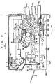
- Figs. 1 and 2 schematically show a copying machine as an image forming apparatus according to the embodiment of the invention.
- numeral 1 designates a housing of the copying machine.
- An original table 2 transparent glass
- a swingable original cover 11 and a worktable 12 are arranged beside the original table 2.
- the original set on the original table 2 is scanned for image exposure as an optical system 3 (Fig. 7) including an exposure lamp 4 and mirrors 5, 6 and 7 reciprocates in the direction indicated by arrow a along the under surface of the original table 2.
- the mirrors 6 and 7 move at a speed half that of the mirror 5 so as to maintain a fixed optical path length.
- an image of the original is formed on the surface of the photosensitive drum 10.
- the photosensitive drum 10 rotates in the direction indicated by arrow c so that its surface is wholly charged first by a main charger 11.
- the image of the original is projected on the charged surface of the photosensitive drum 10 by slit exposure, forming an electrostatic latent image on the surface.
- the electrostatic latent image is developed into a visible image (toner image) by two developing units 121 and 122 which store therein, for example, red and black toners, individually, and are alternatively operated as required.
- Paper sheets (image record media) P are delivered one by one from an upper paper cassette 131, a middle paper cassette 132, or a lower paper cassette 133 by a paper-supply roller 141, 142 or 143 and a roller pair 151, 152 or 153, and guided along a paper guide path 161, 162 or 163 to an aligning roller pair 17. Then, each paper sheet P is delivered to a transfer region by the aligning roller pair 17, timed to the formation of the visible image on the photosensitive drum 10.
- the paper cassettes 131, 132 and 133 are removably attached to the lower right end portion of the housing 1, and can be alternatively selected by the operation on a control panel which will be described in detail later.
- the paper cassettes 131, 132 and 133 are provided respectively with cassette size detecting switches 601, 602 and 603 which detect the selected cassette size.
- the detecting switches 601, 602 and 603 are each formed of a plurality of microswitches which are turned on or off in response to the insertion of cassettes of different sizes.
- the paper sheet P delivered to the transfer region comes into intimate contact with the surface of the photosensitive drum 10, in the space between a transfer charger 18 and the drum 10. As a result, the toner image on the photosensitive drum 10 is transferred to the paper sheet P by the agency of the charger 18.
- the paper sheet P is separated from the photosensitive drum 10 by a separation charger 19 and transported by a conveyor belt 20.
- the paper sheet P is delivered to a fixing roller pair 21 as a fixing unit arranged at the terminal end portion of the conveyor belt 20.
- the paper sheet P is discharged into a tray 25 outside the housing 1 by a delivery roller pair 22, a directing gate 23 in a position shown in full line in Fig. 2, and an exit roller pair 24.
- the photosensitive drum 10 is de-electrified by a de-electrification charger 26, when the residual toner on the surface of the drum 10 is removed by a cleaner 26. Thereafter, a residual image on the photosensitive drum 10 is erased by a discharge lamp 27 to restore the initial state.
- numeral 29 designates a cooling fan for preventing the temperature inside the housing 1 from rising.
- the copying machine housing 1 is underlain by a duplex/multicolor copying unit 28 which is adapted for duplex copying on both sides of each paper sheet or multicolor copying on each paper sheet surface.
- the unit 28 includes the directing gate 23, the exit roller pair 24, and a plurality of roller pairs 28b, 28c and 28d for feeding the paper sheet redirected by the gate 23 into a collecting section 28a.
- the collecting section 28a is provided with a delivery roller 28e for delivering the paper sheets temporarily stored in the collecting section 28a.
- the delivery roller 28e can move up and down as indicated by the arrow in accordance with the thickness of a pile of paper sheets (or the number of paper sheets in a pile) stored in the collecting section 28a.
- the paper sheets delivered by the delivery roller pair 28e are guided to a control gate 28g through a separating roller pair 28f for feeding the paper sheets separately, i.e., one by one.
- control gate 28g is rocked in the direction indicated by arrow M so that the paper sheet is guided to the aligning roller pair 17 through a feed roller pair 28h and a paper guide path 28i.
- control gate 28g is shifted to the position shown in Fig. 2 so that the paper sheet is guided to a reversal section 28k by a feed roller pair 28j.
- the control gate 28g is rocked in the direction indicated by arrow T so that the paper sheet advanced by the feed roller pair 28j is guided to the aligning roller pair 17 through the feed roller pair 28h and the paper guide path 28i.
- the duplex and multicolor copying operations of the apparatus with this construction will now be explained.
- the copying mode is selected by the key operation on the control panel.
- a paper sheet having undergone regular one-side copying is guided into the duplex/multicolor copying unit 28 by the directing gate 23 shifted in the direction shown by the dotted line in Fig. 3.
- the paper sheet is guided to the collecting section 28a by the roller pairs 28b, 28c and 28d.
- the delivery roller 28e is located in its upper limit position, and the copied surface of the paper sheet faces downward.
- the delivery roller 28e is lowered to engage the paper sheet, thereby delivering the same.
- the paper sheet is guided to the aligning roller pair 17 by means of the separating roller pair 28f, the control gate 28g shifted in the direction shown by the dotted line in Fig. 3, the feed roller pair 28h, and the paper guide path 28i.
- copying from the second original can be performed.
- the copied surface of the paper sheet faces the photosensitive drum 10, so that an image of the second original is copied onto the paper sheet, superposed on the previously copied image.
- the paper sheet is discharged into the tray 25 through the conveyor belt 20, the fixing roller pair 21, the delivery roller pair 22, the directing gate 23 in the position shown in full line in Fig. 3, and the exit roller pair 24.
- a paper sheet having undergone regular one-side copying is delivered to the collecting section 28a of the duplex/multicolor copying unit 28. Thereafter, when another original is set on the original table 2 and the copy key is depressed, the paper sheet is delivered by the delivery roller 28e. Then, the paper sheet is guided to the reversal section 28k by means of the separating roller pair 28f, the control gate 28g in the position shown in full line, and the feed roller pair 28j.
- the control gate 28g When the trailing end of the paper sheet passes through the control gate 28g, the control gate 28g is shifted to the position shown in the dotted line, and the feed roller pair 28j is reversed.
- the paper sheet is guided to the aligning roller pair 17 by means of the control gate 28g, the feed roller pair 28h, and the paper guide path 28i, to be subjected to copying from the second original.
- the other surface of the paper sheet opposite to the previously copying surface thereof faces the photosensitive drum 10, so that an image of the second original is copied onto the other surface.
- the paper sheet After the copying, the paper sheet is discharged into the tray 25 in the same manner as aforesaid.
- Fig. 5 shows a control panel 30 mounted on the housing 1.
- the control panel 30 carries thereon a copy key 301 for starting the copying operation, ten-keys 302 for setting the number of copies to be made and the like, a display section 303 for indicating the operating conditions of the individual parts or paper jamming, cassette selection keys 304 for alternatively selecting the upper, middle, or lower paper cassette 131, 132 or 133, and cassette display sections 305 for indicating the selected cassette.
- the control panel 30 is further provided with ratio setting keys 306 for setting the enlargement or reduction ratio of copy selected among several predetermined ratios, zoom keys 307 for adjustably setting the enlargement or reduction ratio, a display section 308 for displaying the set ratio, and a density setting section 309 for setting the copy density.
- control panel 30 Additionally arranged on the control panel 30 are operation keys 30a, 30b, 30c and 30d for shifting a spot light source (mentioned later) which serves to indicate erasure positions on the original, a position designating key 30e for inputting the coordinate positions indicated by the spot light source, and erasure range designating keys 30f and 30g for designating the erasure ranges in the designated positions. Furthermore, the control panel 30 carries thereon a multicolor copying designating key 30h, a duplex copying designating key 30i, a red designating key 30j for designating the developing unit 121 which stores a red toner by way of an example, and a black designating key 30k for designating the developing unit 122 which stores a black toner by way of an example.
- the copying machine housing 1 is automatically set so as to perform the regular one-side copying operation.
- Fig. 6 shows a specific arrangement of drive sources for individual drive sections of the copying machine constructed in the aforesaid manner.
- the drive sources include the following motors.
- Numeral 31 designates a motor for lens drive.
- the lens drive motor 31 serves to shift the position of the lens block 8 for magnification or reduction.
- Numeral 32 designates a motor for mirror drive.
- the mirror drive motor 32 serves to change the distance (optical path length) between the mirror 5 and the mirrors 6 and 7 for magnification or reduction.
- Numeral 33 designates a motor for scanning.
- the scanning motor 33 serves to move the exposure lamp 4 and the motors 5, 6, and 7 for scanning the original.
- Numeral 34 designates a motor for shutter drive.
- the shutter drive motor 34 serves to move a shutter (not shown) for adjusting the width of charging of the photosensitive drum 10 by the charger 11 at the time of magnification or reduction.
- Numeral 35 designates a motor used for developing.
- the developing motor 35 serves to drive the developing roller and the like of the developing unit 12.
- Numeral 36 designates a motor used to drive the drum.
- the drum drive motor 36 serves to drive the photosensitive drum 10.
- Numeral 37 designates a motor for fixation.
- the fixing motor 37 serves to drive the sheet conveyor belt 22, the fixing roller pair 23, and the exit roller pair 24.
- Numeral 38 designates a motor for paper supply.
- the paper supply motor 38 serves to drive the paper-supply rollers 15 and 16.
- Numeral 39 designates a motor for feeding sheets.
- the sheet feed motor 39 serves to drive the aligning roller pair 19.
- Numeral 40 designates a motor for fan drive.
- the fan drive motor 40 serves to drive the cooling fan 29.
- Fig. 7 shows a drive mechanism for reciprocating the optical system 3.
- the mirror 5 and the exposure lamp 4 are supported by a first carriage 411, and the mirrors 6 and 7 by a second carriage 412, These carriages 411 and 412 can move parallel in the direction indicated by arrow a, guided by guide rails 421 and 422.
- the four-phase pulse motor 33 drives a pulley 43.
- An endless belt 45 is stretched between the pulley 43 and in idle pulley 44, and one end of the first carriage 411 supporting the mirror 5 is fixed to the middle portion of the belt 45.
- two pulleys 47 are rotatably attached to a guide portion 46 (for the rail 422) of the second carriage 412 supporting the mirrors 6 and 7, spaced in the axial direction of the rail 422.
- a wire 48 is stretched between the two pulleys 47.
- One end of the wire 48 is connected directly to a fixed portion 49, while the other end is connected thereto by means of a coil spring 50.
- the one end of the first carriage 411 is fixed to the middle portion of the wire 48.
- the belt 45 turns around the move the first carriage 411.
- the second carriage 412 also travels. Since the pulleys 47 then serve as movable pulleys, the second carriage 412 travels in the same direction as and at a speed half that of the first carriage 411.
- the traveling direction of the first and second carriages 411 and 412 is controlled by changing the rotating direction of the pulse motor 33.
- the indexes 51 and 52 are attached to a wire 57 which is stretched between pulleys 54 and 55 through the aid of a spring 56.
- the pulley 55 is rotated by a motor 58.
- the distance between the indexes 51 and 52 can be changed by driving the motor 58 in accordance with the sheet size and the enlargement or reduction ratio.
- the first carriage 41 moves to a predetermined position (home position depending on the enlargement or reduction ratio) as the motor 33 is driven in accordance with the sheet size and the ratio.
- a predetermined position home position depending on the enlargement or reduction ratio
- the first carriage 411 is first moved toward the second carriage 412.
- The, the lamp 4 is lighted and the first carriage 411 is moved away from the second carriage 412.
- the lamp 4 is turned off, and the first carriage 411 is returned to the home position.
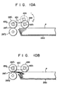
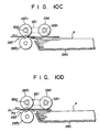
- Fig. 9 shows an arrangement including the delivery roller 28e for taking out the paper sheets P collected in the collecting section 28e and the separating roller pair 28f.
- Rollers 28f1 and 28f2 constituting the separating roller pair 28f are mounted on one end portion of shafts 65a and 65b, respectively.
- a gear 65c is attached to the other end portion of the shaft 65a.
- the gear 65c is in mesh with a gear 66a which is attached to a motor 66.
- the other end portion of the shaft 65b is coupled to one end portion of a shaft 65e by means of a spring clutch 65e.
- a gear 65f is mounted on the other end portion of the shaft 65e.
- the gear 65f is in mesh with the gear 66a.
- a gear 65g is attached to the middle portion of the shaft 65a, and a chain 65i is stretched between the gear 65g and a gear 65h which is attached to the delivery roller 28e.
- the delivery roller 28e is driven in the directions indicated by arrows h and i in Fig. 9 by a drive mechanism (not shown).
- One-way clutches 65k and 65l are provided between the roller 28f1 and the shaft 65a and between the delivery roller 28e and a shaft 65j, respectively.
- the one-way clutches 65k and 65l are adapted to transmit power only when the shafts 65a and 65j rotate in the direction indicated by the arrows.
- the frictional force of the spring clutch 65d is set so that the shafts 65b and 65e slip when the force at the point of contact between the rollers 28f1 and 28f2 exceeds a value V1.
- the frictional force T2 between the rollers 28f1 and 28f2 is greater than the frictional force T1 of the spring clutch 65d. Normally, therefore, the roller 28f2 rotates against the rotatory force of the motor 66, associated with the roller 28f1.
- Fig. 11 shows a general control circuit of the electronic copying machine.
- This control circuit is mainly composed of a main processor group 71 and first and second sub-processor groups 72 and 73.
- the main processor group 71 detects input data from the control panel 30 and a group of input devices 75 including various switches and sensors, such as the cassette size detection switches 601 and 602, and controls a high-voltage transformer 76 for driving the chargers, the discharge lamp 27, a blade solenoid 26a of the cleaner 26, a heater 21a of the fixing roller pair 21, the exposure lamp 4, and the motors 31 to 40, 58, 66 and 77, thus accomplishing the copying operation.
- the main processor group 71 also controls a spot light source 91, a pulse motor 95, an erasure array 100, an array drive section 110, and a memory 120, thereby erasing any unnecessary portions of the original. These components 91, 95, 100, 110 and 120 will be described in detail later.
- the motors 35, 37 and 40 and a toner-supply motor 77 for supplying the toner to the developing unit 12 are connected through a motor driver 78 to the main process group 71 to be controlled thereby.
- the motors 31 to 34 and 95 are connected through a pulse motor driver 79 to the first subprocessor group 72 to be controlled thereby.
- the motors 36, 38, 39, 58 and 66 are connected through a pulse motor driver 80 to the second subprocessor group 73 to be controlled thereby.
- the exposure lamp 4 is controlled by the main processor group 71 through a lamp regulator 81, and the heater 21a by the main processor group 71 through a heater control Section 82.
- the main processor group 71 gives instructions for the start or stop of the individual motors to the first and second sub-processor groups 72 and 73.
- the first and second subprocessor groups 72 and 73 feed the main processor group 17 with status signals indicative of the operation mode of the motors.
- the first sub-processor group 72 is supplied with positional information from a position sensor 83 for detecting the respective initial positions of the motors 31 to 34.
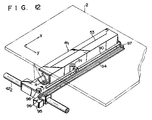
- a guide shaft 90 is disposed at that portion of the first carriage 411 intercepting the light from the lamp 4, extending along the lamp 4.
- the guide shaft 90 is movably fitted with the spot light source 91 as the indicating means for indicating an erasure range of the original.
- the spot light source 91 includes a light emitting element 92, such as a light emitting diode or lamp, and a lens 93 which are opposed to the original table 2.
- a light beam emitted from the light emitting element 92 is applied to the original table 2 through the lens 93, as a spot light with a diameter d of, e.g., 2 mm.
- the spot light has enough brightness to be transmitted through an original G as thick as, e.g., a postcard set on the original table 2.
- the spot light source 91 is coupled to a timing belt (toothed belt) 94 extending along the guide shaft 90.
- the timing belt 94 is stretched between a pulley 96 mounted on the shaft of the pulse motor 95 and a driven pulley 97. As the pulse motor 95 is rotated the spot light source 91 is moved in a direction perpendicular to the scanning direction of the first carriage 411.
- a position sensor 98 formed of a microswitch for detecting the initial position of the spot light source 91 is attached to that portion of the first carriage 411 which is located beside the end portion of the guide shaft 90 on the side of the pulse motor 95.
- the spot light source 91 When the spot light source 91 is moved, for example, it first abuts against the position sensor 94 to have its initial position detected thereby.
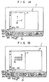
- Figs. 14 to 16 there will be described a method for designating the erasure range of the original by means of the spot light source 91.
- the spot light source 91 is moved by operating the operation keys 30a to 30d.
- the operation keys 30b and 30de are depressed, the motor 33 is started, and the first carriage 411 and the spot light source 91 are moved in the scanning direction (indicated by arrow y in Fig. 14).
- the operation keys 30a and 30c are depressed, on the other hand, the motor 95 is started, and the spot light source 91 is moved in a direction (indicated by arrow x in Fig. 14) perpendicular to the scanning direction.
- the operator Observing the spot light transmitted through the original G, the operator operates the operation keys 30a to 30d.
- the spot light reaches, for example, a spot S1 on the original G shown in Fig. 15, the operator depresses the position designating key 30e.
- the coordinate position indicated by the spot S1 is stored in the main processor group 71 shown in Fig. 11.
- the position designating key 30e is depressed when a spot S2 on the original G is reached by the spot light, the position of the spot S2 is stored in the main processor group 71.
- This position of the spot light can be detected by, for example, counting drive pulses delivered from the pulse motors 33 and 95.
- a rectangular region (hatched region) having its two opposite vertexes on the spots S1 and S2 is designated as the erasure range, as shown in Fig. 15.
- the erasure range designating key 30g is depressed after designating spots S3 and S4 on the original G, the other region of the original G (i.e. not a square region having its two opposite vertexes on the spots S3 and S4) is designated as the erasure range.
- the main processor group 71 executes calculation in accordance with the positions of the two designated spots, and high- and low-level signals "1" and "0" are stored in those addresses of the memory 120 for the erasure range and the remaining region, respectively, as shown in Figs. 17A and 17B for the manners of designation shown in Figs. 15 and 16, respectively.
- the memory 120 is formed of a RAM whose capacity in the direction of each column is substantially equal to a value obtained by dividing the moved distance of the spot light source 91 in the x direction by the positional resolution in the x direction, and whose capacity in the direction of each row is substantially equal to a value obtained by dividing the moved distance of the spot light source 91 by the y direction by the positional resolution in the y direction.
- high- and low-level signals are stored in those addresses of the memory 120 for the hatched region and the other region, respectively, based on data supplied from the main processor group 71.
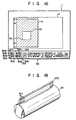
- the erasure array 100 as the erasing means is disposed close to the photosensitive drum 10, between the charger 11 and an expsoure region Ph, for example.
- the erasure array 100 includes a plurality of shading cells 101 which are arranged in a direction perpendicular to the rotating direction of the photosensitive drum 10.
- the cells 101 each contains therein a light emitting element 102 formed of, e.g., a light emitting diode.
- a lens 103 for converging light from the light emitting element 102 on the surface of the photosensitive drum 10 is disposed at the opening portion of each cell 101 facing the photosensitive drum 10.
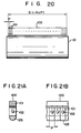
- the erasure array 100 is driven by the array drive section 110.
- the array drive section 110 includes a shift register 111 having the same number of bits as that in the column direction of the memory 120, a store register 112 for holding the contents of the shift register 111, and a switch circuit 114 consisting of a plurality of switch elements 113 adapted to be turned on or off in response to output signals from the store register 112.
- the respective movable contacts 113a of the switch elements 113 are grounded, while their fixed contacts 113b are connected to the respective cathodes of the light emitting elements 102 constituting the erasure array 100.
- the anodes of the light emitting elements 102 are connected to a power source V cc through current-limiting resistors R, individually.
- the first carriage 411 and the photosensitive drum 10 are actuated, and data D1 for one column are successively read out in the row direction from the memory 120.
- the read data D1 are transferred to the shift register 111 of the array drive section 110 in response to clock signals CLK.
- the main processor group 71 delivers a latch signal LTH. In response to the latch signal LTH, the data having so far been stored in the shift register 111 is stored in the store register 112.
- the erasure array 100 may be disposed either between the charger 11 and the exposure region Ph. (Fig. 18) or between the exposure region PH and the developing unit 12 (Fig. 24). Therefore, if the angle between the erasure array 100 and the exposure region Ph and the angular velocity of the photosensitive drum 10 are ⁇ and ⁇ , respectively, the output timing of the latch signal LTH is controlled so that data for one row delivered from the memory 120 are supplied to the store register 112 within a time equivalent to ⁇ / ⁇ .
- the individual switch elements 113 of the switch circuit 114 are controlled by the output signals of the store register 112. If the output level of the store register 112 is high, the switch elements 113 are turned on; if low, then off. Thus, the light emitting elements 102 connected to the switch elements 113 are turned on and off when their corresponding switch elements 113 are turned on and off, respectively. Accordingly, those portions of the charged surface of the photosensitive drum 10 which correspond to the glowing light emitting elements 102 are de-electrified. Even though exposed thereafter, the de-electrified portions will never bear any electrostatic latent image thereon. Thus, the erasing of the original image is accomplished. Thereafter, the data in the memory 120 are read out column by column for image erasing.
- a copy image consisting of, e.g., a black portion G1 and a red portion G2 may be obtained from a unicolor original G, as shown in Fig. 23A.
- the original G is set on the original table 2, and the multicolor copying designating key 30h and a black designating key 30k, for example, are depressed first.
- the operation keys 30a to 30d, the position designating key 30e, and the erasure range designating key 30f are operated so that the red copy portion G2 is designated as an erasure range by coordinates (Sa, Sb), as shown in Fig. 23B.
- the copy key 301 is depressed in this state, only the portion G1 is formed on the paper sheet P with use of the black toner, as shown in Fig. 23C, and the paper sheet P is temporarily stored in the collecting section 28a.
- the black copy portion G1 (which corresponds to all portions of the paper sheet P other than the range defined by the coordinates (Sa, Sb)) is designated as an erasure range.
- the red designating key 30j and the copy key 301 are depressed in succession, the paper sheet P carrying only the portion G1 shown in Fig. 23C is taken out from the collecting section 28a.
- the original image is formed on the paper sheet P with the use of the black and red toners for the portions G1 and G2, respectively.
- the toner colors are not limited to red and black.
- the apparatus has a duplex copying function, a function to selectively erase any undesired portions of the original image, and a multicolor copying function. Accordingly, a multicolor original may be copied to form a colorful, clear copy image in which the color of one portion is different from that of another.
- spot light source 91 is mounted on the first carriage 411, furthermore, use of space is efficient enough to restrain the apparatus from becoming too bulky.
- the present invention is not limited to the above embodiment.
- the erasure array 100 may be arranged between the exposure region Ph and the developing unit 12, as shown in Fig. 24, so that the formed electrostatic latent image is erased as specified.
- the capacity of the memory 120 may be changed as required.
- the apparatus is provided with the two developing units 121 and 122 which individually use two developing agents of different colors for forming a two-color copy image.
- the present invention is not limited to such an arrangement, and the developing agents used in the first and second developing units 121 and 122 may be of the same color.
- the developing agent used in the first developing unit 121 may, for example, be selected for a sharp copy image, and the developing agent in the second developing unit 122 for a soft copy image.
- the image quality is changed by varying the type of developing agent.
- the image quality may be selected by rotating the respective developing rollers of the two developing units 121 and 122 in different directions, i.e., with mode against mode, without changing the type of developing agent used.
- two developing processes are executed with use of two developing units.
- the image color or quality may be changed by replacing a single provided developing unit with another, depending on the color or property of the developing agent to be used.
- a paper sheet having undergone a first copying cycle is automatically returned to the paper supply section by the duplex/multicolor copying unit 28.
- the paper cassettes 131, 132 and 133 may be given a manual sheet feed function. In this case, a paper sheet is simply discharged without using the duplex/multicolor copying unit 28 after it is subjected to the first copying cycle. The discharged paper sheet is manually fed again into the apparatus through the proper cassette 131, 132 and 133 for multicolor copying.
- an image forming apparatus of very high utility value in which desired portions of an original image are designated and developed in one developing process, and portions other than the designated portions are developed in another developing process so that a copy image of a single original can be formed with use of different developing processes.
Landscapes
- Physics & Mathematics (AREA)
- General Physics & Mathematics (AREA)
- Control Or Security For Electrophotography (AREA)
Claims (7)
- Gerät zur Herstellung von Bildern, umfassend:
einen lichtempfindlichen Körper (10), der an seiner Oberfläche eine elektrische Ladung hält,
eine Aufladeeinrichtung (11) zum gleichmäßigen Aufbringen einer elektrischen Ladung auf die Oberfläche des lichtempfindlichen Körpers (10),
einen durchsichtigen Vorlagentisch (2), der eine Vorlage (G) tragen kann,
eine Bildbelichtungseinrichtung (3) zum Belichten der Oberfläche des lichtempfindlichen Körpers (10), der durch die Aufladeeinrichtung (11) gleichmäßig aufgeladen worden ist, mit (einem) ein Bild der Vorlage (G) auf dem Vorlagentisch (2) repräsentierenden Licht, um dadurch auf der Oberfläche des lichtempfindlichen Körpers (10) in Abhängigkeit vom Vorlagenbild ein elektrisches Ladungsmuster zu bilden,
eine Entwicklungseinrichtung (12₁, 12₂) zum Entwickeln eines auf der Oberfläche des lichtempfindlichen Körpers (10) erzeugten Latentbilds, das durch das elektrische Ladungsmuster bestimmt oder definiert ist,
wobei die Entwicklungseinrichtung (12₁, 12₂) so ausgeführt ist, daß sie alternativ Entwicklungsmittel verschiedener Arten zur Oberfläche des lichtempfindlichen Körpers (10) liefert und mittels des gelieferten Entwicklungsmittels denjenigen Teil des lichtempfindlichen Körpers (10) entwickelt, der einem spezifischen, durch eine Anzeigeeinrichtung (91) angezeigten Bereich der Vorlage (G) entspricht, und
eine Löscheinrichtung (100) zum Löschen der elektrischen Ladung an demjenigen Teil des lichtempfindlichen Körpers (10), welcher von dem Oberflächenteil verschieden ist, der dem durch die Anzeigeeinrichtung (91) angezeigten spezifischen Bereich der Vorlage entspricht,
wobei die Anzeigeeinrichtung (91) einen spezifischen rechteckigen Bereich einer gewählten Länge und Breite als den Bereich der Vorlage anzeigt, der mit Hilfe von Toner(n) verschiedener Arten zu kopieren ist,
und die Löscheinrichtung (100) durch einen AnordnungsAnsteuerabschnitt (110) gesteuert ist, der eine Operations- bzw. Betriebszeit und eine Beleuchtungsbreite in Beziehung zum spezifischen rechteckigen Bereich berechnet,
dadurch gekennzeichnet, daß die Anzeigeeinrichtung eine Lichtaussendeeinrichtung (91) zum Anlegen (Aufstrahlen) eines Punktlichts an (auf) die auf dem durchsichtigen Vorlagentisch (2) befindliche Vorlage (G) von der Unterseite derselben her aufweist, und die Lichtaussendeeinrichtung so verschiebbar ist, daß der Perimeter des spezifischen rechteckigen Bereichs durch Verschieben der Lichtaussendeeinrichtung zu zwei spezifischen Punkten an diagonal gegenüberliegenden Ecken des spezifischen rechteckigen Bereichs definiert wird, wobei die Verschiebung der Lichtaussendeeinrichtung durch eine Eirstelleinrichtung (30a ... 30g) gesteuert ist. - Gerät zur Herstellung von Bildern nach Anspruch 1, dadurch gekennzeichnet, daß die Einstelleinrichtung eine erste Einstelleinrichtung (30f) zum Einstellen des spezifischen Bereichs innerhalb des Perimeters und eine zweite Einstelleinrichtung (30g) zum Einstellen des spezifischen Bereichs außerhalb des Perimeters aufweist.
- Gerät zur Herstellung von Bildern nach Anspruch 1, dadurch gekennzeichnet, daß die Entwicklungseinrichtung eine erste Entwicklungseinheit (12₁) zum Liefern eines ersten Entwicklungsmittels zu der Oberfläche des lichtempfindlichen Körpers (10) und eine zweite Entwicklungseinheit (12₂) zum Liefern eines zweiten Entwicklungsmittels zu der Oberfläche des lichtempfindlichen Körpers (10) aufweist.
- Gerät zur Herstellung von Bildern nach Anspruch 3, dadurch gekennzeichnet, daß die Entwicklungseinrichtung (12₁, 12₂) alternativ das erste und das zweite Entwicklungsmittel liefert, so daß derjenige Teil der Oberfläche des lichtempfindlichen Körpers (10), der dem durch die erste Einstelleinrichtung (30f) eingestellten spezifischen Bereich entspricht, mit dem ersten Entwicklungsmittel entwickelt wird und derjenigen Teil der Oberfläche des lichtempfindlichen Körpers (10), der dem durch die zweite Einstelleinrichtung (30g) eingestellten spezifischen Bereich entspricht, mit dem zweiten Entwicklungsmittel entwickelt wird.
- Gerät zur Herstellung von Bildern nach Anspruch 3 oder 4, dadurch gekennzeichnet, daß das erste Entwicklungsmittel einen Toner einer ersten Farbe und das zweite Entwicklungsmittel einen Toner einer zweiten Farbe, die von der ersten Farbe verschieden ist, umfaßt.
- Gerät zur Herstellung von Bildern nach Anspruch 5, dadurch gekennzeichnet, daß die erste und die zweite Farbe schwarz bzw. rot sind.
- Gerät zur Herstellung von Bildern nach Anspruch 1, dadurch gekennzeichnet, daß der spezifische rechteckige Bereich durch zwei Lichtpunkte (S₁, S₂) definiert ist.
Applications Claiming Priority (2)
| Application Number | Priority Date | Filing Date | Title |
|---|---|---|---|
| JP193224/84 | 1984-09-14 | ||
| JP59193224A JPS6170564A (ja) | 1984-09-14 | 1984-09-14 | 画像形成装置 |
Publications (3)
| Publication Number | Publication Date |
|---|---|
| EP0179253A1 EP0179253A1 (de) | 1986-04-30 |
| EP0179253B1 EP0179253B1 (de) | 1989-12-27 |
| EP0179253B2 true EP0179253B2 (de) | 1994-05-11 |
Family
ID=16304378
Family Applications (1)
| Application Number | Title | Priority Date | Filing Date |
|---|---|---|---|
| EP85111538A Expired - Lifetime EP0179253B2 (de) | 1984-09-14 | 1985-09-12 | Gerät zur Herstellung von Bildern |
Country Status (4)
| Country | Link |
|---|---|
| US (1) | US4685794A (de) |
| EP (1) | EP0179253B2 (de) |
| JP (1) | JPS6170564A (de) |
| DE (1) | DE3575028D1 (de) |
Families Citing this family (33)
| Publication number | Priority date | Publication date | Assignee | Title |
|---|---|---|---|---|
| US4794421A (en) * | 1983-05-12 | 1988-12-27 | Eastman Kodak Company | Apparatus and method for electrophotographically producing copies from originals having continuous-tone and other content |
| JPH068973B2 (ja) * | 1985-06-05 | 1994-02-02 | キヤノン株式会社 | 多色画像形成方法 |
| JPS6247667A (ja) * | 1985-08-27 | 1987-03-02 | Canon Inc | 照明装置 |
| US4799080A (en) * | 1985-10-19 | 1989-01-17 | Sanyo Electric Co., Ltd. | Electrophotographic copying machine having editorial function |
| US5006890A (en) * | 1985-11-18 | 1991-04-09 | Canon Kabushiki Kaisha | Image forming apparatus with a provision for designating different colored image areas |
| JPS63124074A (ja) * | 1986-11-13 | 1988-05-27 | Minolta Camera Co Ltd | 現像器 |
| DE3802227A1 (de) * | 1987-01-26 | 1988-08-04 | Minolta Camera Kk | Mehrfarben-abbildungsgeraet |
| US4862216A (en) * | 1987-01-28 | 1989-08-29 | Minolta Camera Kabushiki Kaisha | Multicolor copying apparatus |
| US4952987A (en) * | 1987-02-24 | 1990-08-28 | Minolta Camera Kabushiki Kaisha | Copying machine having plural developing units |
| US4857958A (en) * | 1987-03-25 | 1989-08-15 | Kabushiki Kaisha Toshiba | Electronic copying apparatus having function of partially changing image reproduced from original image |
| JPS63237077A (ja) * | 1987-03-25 | 1988-10-03 | Minolta Camera Co Ltd | 多色画像形成装置 |
| US4860049A (en) * | 1987-04-30 | 1989-08-22 | Kabushiki Kaisha Toshiba | Image forming apparatus |
| US4761669A (en) * | 1987-05-21 | 1988-08-02 | Xerox Corporation | Highlight color printing |
| DE3863488D1 (de) * | 1987-05-28 | 1991-08-08 | Minolta Camera Kk | Bildvervielfaeltigungsgeraet. |
| US4924264A (en) * | 1987-06-30 | 1990-05-08 | Minolta Camera Kabushiki Kaisha | Image duplicating apparatus having edited copying mode |
| JPS649474A (en) * | 1987-07-01 | 1989-01-12 | Minolta Camera Kk | Copying device capable of simultaneous multicolor copying |
| JPS6420575A (en) * | 1987-07-15 | 1989-01-24 | Minolta Camera Kk | Multicolor copying machine |
| JPS6424263A (en) * | 1987-07-21 | 1989-01-26 | Minolta Camera Kk | Multicolor image forming device |
| US5028958A (en) * | 1987-08-21 | 1991-07-02 | Minolta Camera Kabushiki Kaisha | Copying apparatus with simultaneous multi-color single cycle copying |
| JPS6473363A (en) * | 1987-09-14 | 1989-03-17 | Minolta Camera Kk | Exposure controller in image forming device |
| US4804603A (en) * | 1987-09-21 | 1989-02-14 | Eastman Kodak Company | Electrophotographic method and apparatus |
| US5105217A (en) * | 1987-10-21 | 1992-04-14 | Minolta Camera Kabushiki Kaisha | Copying apparatus with grid forming function |
| JPH01123264A (ja) * | 1987-11-09 | 1989-05-16 | Minolta Camera Co Ltd | 同時2色複写可能な複写装置 |
| DE68918119T2 (de) * | 1988-01-18 | 1995-04-27 | Minolta Camera Kk | Verfahren und Gerät zur Erzeugung von mehrfarbigen Bildern. |
| JPH01185675A (ja) * | 1988-01-19 | 1989-07-25 | Minolta Camera Co Ltd | 作像装置 |
| US4914454A (en) * | 1988-04-14 | 1990-04-03 | Minolta Camera Kabushiki Kaisha | Image recording system capable of forming image with different colors in different areas |
| US5241155A (en) * | 1988-11-25 | 1993-08-31 | Canon Kabushiki Kaisha | Image fixing apparatus having linear heat generating layer with variable resistance distribution |
| US4998144A (en) * | 1989-12-26 | 1991-03-05 | Eastman Kodak Company | Color palette for copiers |
| TWI345211B (en) * | 2002-05-17 | 2011-07-11 | Semiconductor Energy Lab | Display apparatus and driving method thereof |
| US7474285B2 (en) * | 2002-05-17 | 2009-01-06 | Semiconductor Energy Laboratory Co., Ltd. | Display apparatus and driving method thereof |
| TWI360098B (en) * | 2002-05-17 | 2012-03-11 | Semiconductor Energy Lab | Display apparatus and driving method thereof |
| US7184034B2 (en) * | 2002-05-17 | 2007-02-27 | Semiconductor Energy Laboratory Co., Ltd. | Display device |
| US9300098B1 (en) | 2015-02-03 | 2016-03-29 | Hubbell Incorporated | Adjustable pad mount substation adapter plates |
Family Cites Families (9)
| Publication number | Priority date | Publication date | Assignee | Title |
|---|---|---|---|---|
| NL279524A (de) * | 1961-06-08 | |||
| US3390989A (en) * | 1964-04-15 | 1968-07-02 | Itek Corp | Methods of imaging a data storage medium |
| JPS4834770B1 (de) * | 1968-07-23 | 1973-10-23 | ||
| DE2026387A1 (de) * | 1969-05-31 | 1971-01-07 | Canon K K , Tokio | Elektrofotografischer Mehrfarbenverviel faltiger mit automatischer Behchtungssteue rang und Farbentrennung |
| US3914043A (en) * | 1974-03-29 | 1975-10-21 | Xerox Corp | Color accenting copying machine |
| JPS56158347A (en) * | 1980-05-12 | 1981-12-07 | Iwatsu Electric Co Ltd | Copying machine |
| JPS5810771A (ja) * | 1981-07-13 | 1983-01-21 | Canon Inc | 画像形成装置 |
| JPS5915948A (ja) * | 1982-07-19 | 1984-01-27 | Canon Inc | 画像形成機 |
| JPS5977768A (ja) * | 1982-10-26 | 1984-05-04 | Fuji Xerox Co Ltd | 原稿の位置指定装置 |
-
1984
- 1984-09-14 JP JP59193224A patent/JPS6170564A/ja active Pending
-
1985
- 1985-09-12 DE DE8585111538T patent/DE3575028D1/de not_active Expired - Lifetime
- 1985-09-12 EP EP85111538A patent/EP0179253B2/de not_active Expired - Lifetime
- 1985-09-13 US US06/776,134 patent/US4685794A/en not_active Expired - Fee Related
Also Published As
| Publication number | Publication date |
|---|---|
| DE3575028D1 (de) | 1990-02-01 |
| JPS6170564A (ja) | 1986-04-11 |
| EP0179253A1 (de) | 1986-04-30 |
| US4685794A (en) | 1987-08-11 |
| EP0179253B1 (de) | 1989-12-27 |
Similar Documents
| Publication | Publication Date | Title |
|---|---|---|
| EP0179253B2 (de) | Gerät zur Herstellung von Bildern | |
| US4763165A (en) | Image forming apparatus with image adding function | |
| US4690543A (en) | Image forming apparatus with a plurality of colors | |
| EP0180984B1 (de) | Bilderzeugungsgerät mit selektivem Bilderzeugungsbereich | |
| US4666288A (en) | Image forming apparatus with area selection and confirmation | |
| US4752809A (en) | Copying machine for selective reproduction of images | |
| US4711553A (en) | Image forming apparatus with a plurality of colors | |
| US4720729A (en) | Image forming apparatus with editing function | |
| EP0175962B1 (de) | Elektrophotographisches Bilderzeugungsgerät | |
| JPS6236681A (ja) | 画像形成装置 | |
| US4903077A (en) | Electronic copying apparatus with trimming function | |
| EP0223339A1 (de) | Bilderzeugungsgerät | |
| JPS61212863A (ja) | 画像形成装置 | |
| JP2666957B2 (ja) | 画像形成装置 | |
| JPS61238071A (ja) | 画像形成装置 | |
| JPS6221174A (ja) | 画像形成装置 | |
| JPS625763A (ja) | 画像形成装置 | |
| JPS61272764A (ja) | 画像形成装置 | |
| JPS6244768A (ja) | 画像形成装置 | |
| JPS61103174A (ja) | 画像形成装置 | |
| JPS62222277A (ja) | 画像形成装置 | |
| JPS61246770A (ja) | 画像形成装置 | |
| JPS6261084A (ja) | 画像形成装置 | |
| JPS6236680A (ja) | 画像形成装置 | |
| JPS61105571A (ja) | 画像形成装置 |
Legal Events
| Date | Code | Title | Description |
|---|---|---|---|
| PUAI | Public reference made under article 153(3) epc to a published international application that has entered the european phase |
Free format text: ORIGINAL CODE: 0009012 |
|
| 17P | Request for examination filed |
Effective date: 19851009 |
|
| AK | Designated contracting states |
Kind code of ref document: A1 Designated state(s): DE FR GB NL |
|
| 17Q | First examination report despatched |
Effective date: 19871127 |
|
| GRAA | (expected) grant |
Free format text: ORIGINAL CODE: 0009210 |
|
| AK | Designated contracting states |
Kind code of ref document: B1 Designated state(s): DE FR GB NL |
|
| REF | Corresponds to: |
Ref document number: 3575028 Country of ref document: DE Date of ref document: 19900201 |
|
| ET | Fr: translation filed | ||
| PLBI | Opposition filed |
Free format text: ORIGINAL CODE: 0009260 |
|
| 26 | Opposition filed |
Opponent name: BSG TECHNISCHE BERATUNGS-GESELLSCHAFT MBH Effective date: 19900926 |
|
| PLAB | Opposition data, opponent's data or that of the opponent's representative modified |
Free format text: ORIGINAL CODE: 0009299OPPO |
|
| NLR1 | Nl: opposition has been filed with the epo |
Opponent name: BSG TECHNISCHE BERATUNGS-GESELLSCHAFT MBH |
|
| R26 | Opposition filed (corrected) |
Opponent name: BSG TECHNISCHE BERATUNGS-GESELLSCHAFT MBH Effective date: 19900926 |
|
| PUAH | Patent maintained in amended form |
Free format text: ORIGINAL CODE: 0009272 |
|
| STAA | Information on the status of an ep patent application or granted ep patent |
Free format text: STATUS: PATENT MAINTAINED AS AMENDED |
|
| 27A | Patent maintained in amended form |
Effective date: 19940511 |
|
| AK | Designated contracting states |
Kind code of ref document: B2 Designated state(s): DE FR GB NL |
|
| NLR2 | Nl: decision of opposition | ||
| NLR3 | Nl: receipt of modified translations in the netherlands language after an opposition procedure | ||
| ET3 | Fr: translation filed ** decision concerning opposition | ||
| PGFP | Annual fee paid to national office [announced via postgrant information from national office to epo] |
Ref country code: GB Payment date: 19960903 Year of fee payment: 12 |
|
| PGFP | Annual fee paid to national office [announced via postgrant information from national office to epo] |
Ref country code: FR Payment date: 19960910 Year of fee payment: 12 |
|
| PGFP | Annual fee paid to national office [announced via postgrant information from national office to epo] |
Ref country code: DE Payment date: 19960920 Year of fee payment: 12 |
|
| PGFP | Annual fee paid to national office [announced via postgrant information from national office to epo] |
Ref country code: NL Payment date: 19960930 Year of fee payment: 12 |
|
| PG25 | Lapsed in a contracting state [announced via postgrant information from national office to epo] |
Ref country code: GB Free format text: LAPSE BECAUSE OF NON-PAYMENT OF DUE FEES Effective date: 19970912 |
|
| PG25 | Lapsed in a contracting state [announced via postgrant information from national office to epo] |
Ref country code: FR Free format text: THE PATENT HAS BEEN ANNULLED BY A DECISION OF A NATIONAL AUTHORITY Effective date: 19970930 |
|
| PG25 | Lapsed in a contracting state [announced via postgrant information from national office to epo] |
Ref country code: NL Free format text: LAPSE BECAUSE OF NON-PAYMENT OF DUE FEES Effective date: 19980401 |
|
| GBPC | Gb: european patent ceased through non-payment of renewal fee |
Effective date: 19970912 |
|
| NLV4 | Nl: lapsed or anulled due to non-payment of the annual fee |
Effective date: 19980401 |
|
| PG25 | Lapsed in a contracting state [announced via postgrant information from national office to epo] |
Ref country code: DE Free format text: LAPSE BECAUSE OF NON-PAYMENT OF DUE FEES Effective date: 19980603 |
|
| REG | Reference to a national code |
Ref country code: FR Ref legal event code: ST |