EP0179371A2 - Einrichtung zum Pumpen eines Fluidums - Google Patents
Einrichtung zum Pumpen eines Fluidums Download PDFInfo
- Publication number
- EP0179371A2 EP0179371A2 EP85112939A EP85112939A EP0179371A2 EP 0179371 A2 EP0179371 A2 EP 0179371A2 EP 85112939 A EP85112939 A EP 85112939A EP 85112939 A EP85112939 A EP 85112939A EP 0179371 A2 EP0179371 A2 EP 0179371A2
- Authority
- EP
- European Patent Office
- Prior art keywords
- glycol
- piston
- wet
- wet glycol
- fluid
- Prior art date
- Legal status (The legal status is an assumption and is not a legal conclusion. Google has not performed a legal analysis and makes no representation as to the accuracy of the status listed.)
- Withdrawn
Links
- 239000012530 fluid Substances 0.000 title claims abstract description 53
- 238000005086 pumping Methods 0.000 title claims abstract description 45
- LYCAIKOWRPUZTN-UHFFFAOYSA-N Ethylene glycol Chemical compound OCCO LYCAIKOWRPUZTN-UHFFFAOYSA-N 0.000 claims abstract description 392
- WGCNASOHLSPBMP-UHFFFAOYSA-N hydroxyacetaldehyde Natural products OCC=O WGCNASOHLSPBMP-UHFFFAOYSA-N 0.000 claims abstract description 196
- 239000006096 absorbing agent Substances 0.000 claims abstract description 46
- VNWKTOKETHGBQD-UHFFFAOYSA-N methane Chemical compound C VNWKTOKETHGBQD-UHFFFAOYSA-N 0.000 claims abstract description 28
- XLYOFNOQVPJJNP-UHFFFAOYSA-N water Substances O XLYOFNOQVPJJNP-UHFFFAOYSA-N 0.000 claims abstract description 28
- 239000003345 natural gas Substances 0.000 claims abstract description 14
- 230000002441 reversible effect Effects 0.000 claims abstract description 10
- 239000003795 chemical substances by application Substances 0.000 claims abstract 2
- 238000006073 displacement reaction Methods 0.000 claims description 5
- 238000007599 discharging Methods 0.000 claims 2
- 238000007789 sealing Methods 0.000 claims 1
- 239000002274 desiccant Substances 0.000 abstract 1
- 239000007789 gas Substances 0.000 description 51
- 239000007788 liquid Substances 0.000 description 6
- 238000010438 heat treatment Methods 0.000 description 4
- 238000001816 cooling Methods 0.000 description 3
- 230000006870 function Effects 0.000 description 3
- 230000009467 reduction Effects 0.000 description 3
- 125000006850 spacer group Chemical group 0.000 description 3
- 239000002699 waste material Substances 0.000 description 3
- 230000008901 benefit Effects 0.000 description 2
- 238000010276 construction Methods 0.000 description 2
- 230000018044 dehydration Effects 0.000 description 2
- 238000006297 dehydration reaction Methods 0.000 description 2
- 239000000203 mixture Substances 0.000 description 2
- 230000000737 periodic effect Effects 0.000 description 2
- 230000008016 vaporization Effects 0.000 description 2
- 230000000712 assembly Effects 0.000 description 1
- 238000000429 assembly Methods 0.000 description 1
- 230000008859 change Effects 0.000 description 1
- 239000000470 constituent Substances 0.000 description 1
- 230000003247 decreasing effect Effects 0.000 description 1
- 239000012024 dehydrating agents Substances 0.000 description 1
- 230000001419 dependent effect Effects 0.000 description 1
- 238000010586 diagram Methods 0.000 description 1
- 230000007613 environmental effect Effects 0.000 description 1
- 230000005484 gravity Effects 0.000 description 1
- 239000000463 material Substances 0.000 description 1
- 230000007246 mechanism Effects 0.000 description 1
- 238000012544 monitoring process Methods 0.000 description 1
- 230000007659 motor function Effects 0.000 description 1
- 230000007935 neutral effect Effects 0.000 description 1
- 239000003921 oil Substances 0.000 description 1
- 238000009834 vaporization Methods 0.000 description 1
Images



Classifications
-
- F—MECHANICAL ENGINEERING; LIGHTING; HEATING; WEAPONS; BLASTING
- F04—POSITIVE - DISPLACEMENT MACHINES FOR LIQUIDS; PUMPS FOR LIQUIDS OR ELASTIC FLUIDS
- F04B—POSITIVE-DISPLACEMENT MACHINES FOR LIQUIDS; PUMPS
- F04B9/00—Piston machines or pumps characterised by the driving or driven means to or from their working members
- F04B9/08—Piston machines or pumps characterised by the driving or driven means to or from their working members the means being fluid
- F04B9/10—Piston machines or pumps characterised by the driving or driven means to or from their working members the means being fluid the fluid being liquid
- F04B9/109—Piston machines or pumps characterised by the driving or driven means to or from their working members the means being fluid the fluid being liquid having plural pumping chambers
- F04B9/111—Piston machines or pumps characterised by the driving or driven means to or from their working members the means being fluid the fluid being liquid having plural pumping chambers with two mechanically connected pumping members
- F04B9/115—Piston machines or pumps characterised by the driving or driven means to or from their working members the means being fluid the fluid being liquid having plural pumping chambers with two mechanically connected pumping members reciprocating movement of the pumping members being obtained by two single-acting liquid motors, each acting in one direction
-
- B—PERFORMING OPERATIONS; TRANSPORTING
- B01—PHYSICAL OR CHEMICAL PROCESSES OR APPARATUS IN GENERAL
- B01D—SEPARATION
- B01D53/00—Separation of gases or vapours; Recovering vapours of volatile solvents from gases; Chemical or biological purification of waste gases, e.g. engine exhaust gases, smoke, fumes, flue gases, aerosols
- B01D53/26—Drying gases or vapours
- B01D53/263—Drying gases or vapours by absorption
-
- C—CHEMISTRY; METALLURGY
- C10—PETROLEUM, GAS OR COKE INDUSTRIES; TECHNICAL GASES CONTAINING CARBON MONOXIDE; FUELS; LUBRICANTS; PEAT
- C10G—CRACKING HYDROCARBON OILS; PRODUCTION OF LIQUID HYDROCARBON MIXTURES, e.g. BY DESTRUCTIVE HYDROGENATION, OLIGOMERISATION, POLYMERISATION; RECOVERY OF HYDROCARBON OILS FROM OIL-SHALE, OIL-SAND, OR GASES; REFINING MIXTURES MAINLY CONSISTING OF HYDROCARBONS; REFORMING OF NAPHTHA; MINERAL WAXES
- C10G2300/00—Aspects relating to hydrocarbon processing covered by groups C10G1/00 - C10G99/00
- C10G2300/10—Feedstock materials
- C10G2300/1025—Natural gas
Definitions
- This invention relates to a fluid pumping system and, more particularly, to a fluid pumping system adapted for use with a natural gas dehydrating system of the type employed at a gas well head to remove water from a well stream composed of a mixture of gas, oil and water.
- such systems comprise a separator means for receiving the gas-oil-water mixture from the well head and separating the oil and water liquids from "wet" (water vapor laden) gas; and a water absorber means, which employs a liquid dehydrating agent such as glycol, for removing the water vapor from the wet gas and producing "dry” gas suitable for commercial usage.
- a liquid dehydrating agent such as glycol
- the wet glycol is continuously removed from the absorber means and circulated through a treater means such as a reboiler means for removing the absorbed water from the glycol to provide a new supply of dry glycol.
- the glycol reboiler means usually comprises a still column associated with a gas burner for heating the wet glycol to produce hot dry glycol by removing the absorbed water and any entrained gas by vaporization.
- the hot dry glycol passes through a heat exchanger, where the hot glycol is cooled and the incoming wet glycol is heated, to a dry glycol storage tank.
- a glycol passage means is provided to enable passage of wet glycol from the absorber means to the reboiler means and to pump dry glycol from the storage tank to the absorber means.
- the absorber means operates at a relatively high pressure (usually 50 psig to 2000 psig) while the reboiler means which removes the absorbed constituent from the wet glycol operates at a relatively low pressure, e.g., atmospheric pressure.
- the circulation rate of glycol required to achieve dehydration is a function of the natural gas flow rate, temperature and pressure. Since the dehydrating systems are continuously operated at a well site without continuous monitoring by operating personnel, reliable continuous operation of the glycol pump is of critical importance. In addition, it is highly desirable to use energy sources available at the well site for operation of the pump with maximum efficiency and minimum energy loss.
- the present invention provides a new improved glycol pumping system which is operated by an available energy source other than the saleable dry natural gas at the well head; which may be operated at relatively low speeds and pressures without stalling; and which is automatically continuously operable under a wide range of operating conditions
- Each of the pumping devices described in these patents and the device of the present invention include a pump section and a motor section.
- the function of the pump section is to pump dry glycol from a treater or reboiler back into the absorber vessel.
- the function of the motor section is twofold. It provides power to drive the pump section and also meters the flow of wet glycol out of the absorber and back into the treater or reboiler.
- the wet glycol returned from the absorber to the treater means would provide sufficient energy to power the pump which pumps dry glycol from the treater back into the absorber.
- the motor would have an excess of energy since the wet glycol and disolved gas therein metered out through the pump motor is greater in volume, generally at least 3% greater, than the dry glycol pumped back into the absorber.
- Ideal pumping conditions cannot be achieved since significant flow losses and friction are present in an actual physical system. Prior art pumping systems have utilized well gas to increase the pumping energy of the system to make up for these friction and flow energy losses.
- the device of U. S. Patent 2,990,910 derives the power for the motor section entirely from the fluid metered out of the absorber and returned to the treater.
- the excess energy required to overcome friction, etc. is obtained by making the volumetric displacement of the motor section greater than the volumetric displacement of the pump section.
- the amount of volumetric imbalance is typically 25% to 50%.
- This imbalance requires a certain volume of natural gas to be metered out of the absorber along with the wet glycol. Generally, this gas is subsequently wasted by being vented into the atmosphere. The environmental and economic impact of this waste is considerable. For example, a gas well producing 10 million cubic feet per day from a 1100 psi well using a pump of the type described in U. S. Patent 2,990,910 may waste about $25,000.00 worth of gas in one year in the pumping operation.
- One objective of the present invention is to achieve a significant gas consumption reduction over the device of U . S. Patent 2,990,910 without resorting to the complexity of the devices of U. S. Patents 4,431,433 and 4,402,652.
- Another objective of the present invention is to provide a pump/pump motor which can be easily and efficiently maintained in the field without return to a central shop area for minor overhaul work.
- Another objective of the present invention is to provide a pump/pump motor in which the volumetric imbalance areas may be rapidly and easily changed to adjust for changing well or delivery conditions.
- Another objective of the present invention is to provide a pump/pump motor which will reliably restart when automatically stopped and started on a well which is periodically "stop clocked".
- Another objective of the present invention is to provide a pump/pump motor which, because of reduced friction and other features, will pump over a wider pressure range and run at much lower speeds without stalling, than existing units.
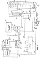
- a pump/pump motor means 18 of the present invention comprises combined pump motor section 19 and pump section 20 which are shown in association with the major components of a three-phased dual-contact conventional natural gas dehydration system comprising: a gas-liquid separator means 22 for removing oil and water liquids from water vapor laden well gas; a packed glycol-gas contactor means 24 for first stage removal of water vapor from the well gas by contacting the well gas with dry glycol during concurrent downward flow thereof; an absorber means 26 for second stage removal of water vapor from the well gas, including an internal tray stack means 28 for providing a downward gravity flow of dry glycol with upward counter flow of the well gas therethrough and an internal gas-glycol heat exchanger means 30 for cooling of dry glycol prior to entry of the dry glycol into the stack tray means 28; an external gas-glycol heat exchanger means 32 for cooling the dry glycol prior to entry into the glycol-gas contactor means; a glycol treater means such as reboiler means 34 for removing
- well gas under pressure enters separator means 22 through an inlet line 50.' The well gas is separated into liquid oil, water and wet gas which includes the natural gas and water vapor. Liquid oil and water are removed from the separator through outlet lines 52, 54. Wet gas under pressure is transmitted through a line 56 to the packed glycol-gas contactor means 24 whereat dry glycol from a line 58 is mixed with the wet gas. The dry glycol and wet gas flow downwardly through contactor means 24 wherein the dry glycol absorbs a portion of the water vapor.
- wet glycol and partially wet gas are removed from the contactor means through a line 60 which is connected to the lower end of absorber means 26 between a wet glycol sump 62 at the bottom of the absorber means and stacked tray means 28.
- Wet glycol from line 60 flows downwardly into the glycol sump 62.
- Partially dried wet gas flows upwardly in the absorber through the stacked tray means 28 which provides a downward flow path for dry glycol received from line 64 to the glycol sump.
- Wet glycol is exhausted from the glycol sump 62 to pump motor 19 through a line'80 and delivered to the still column 38 of reboiler means 34 through a line 82, glycol-glycol heat exchanger means 46, and a line 84.
- Wet glycol flows downwardly in the still column means 38 toward reboiler tank means 40 as indicated by dashed line 86.
- the water in the glycol is vaporized by heat obtained from gas burner means 36 through firetube means 42 which extends into the tank means 40. Vaporized water in the form of steam is removed from the upper end of still column means 38 through an outlet line 88.
- Hot dry glycol is collected in tank means 40, flows downwardly through a line 89 into the top of heat exchanger means 46 containing glycol heating coil means 83. Cooled dry glycol is transmitted from the bottom of the heat exchanger tank to the upper portion of dry glycol storage means 44 through a line 90.
- a gas reservoir means 91 is connected to dry gas line 72 by a regulator means 92 which maintains a supply of relatively low pressure (e.g., 50-75 psig) dry gas in reservoir means 91.
- Burner 36 is connected to reservoir 91 by a dry gas line 93 through a regulator means 94, which reduces the pressure of dry gas to approximately 10 psi.
- Gas reservoir 91 has a pressure relief valve 95 to control dry gas pressure therein.
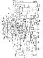
- the pump/pump motor means 18 of the present invention includes two pump/pump motor sections 100L, 100R positioned opposite of each other on a central main body 101.
- the right pump/motor section 100R comprises a cylinder 103R which is mounted on the main body 101 and which is concentrically located about a piston shaft 102 which extends through a bore 158 in the main body 101.
- the right hand pump/motor section also comprises a right piston 105R which is conventionally bolted to shaft 102.
- a cylinder end cap 104R is bolted to the main body and axially clamps the cylinder 103R in fixed relationship with main body 101.
- Seal rings 123 provided in a groove in a shoulder portion of the main body 101 and in a groove in the end cap 104R form a seal at both ends of cylinder 103R to prevent leakage of fluid out of the cylinder.
- the right piston 105R is free to move Axially within the cylinder 103R and is alidingly sealed against the cylinder by O-ring 126R and seal ring 127R.
- a left piston 105L is similarly constructed and arranged with respect to a left cylinder 103L and left end cap 104L.
- the piston shaft 102 comprises two enlarged removeably mounted journal portions 154 and 155 separated by a reduced diameter section 156 and spaced inwardly from smaller diameter end portions 157, 159 which are bolted to pistons 105L, 105R.
- the pushrod journal 154 is slideably sealed in the right end of the main body by a journal seal means including seal ring 124R which is housed and held in the main body 101 by seal retainer 115R and seal spacer 116R. Seal retainer 115R is in turn sealingly engaged by groove mounted seal ring 125R. Snap ring 117R holds seal retainer 115R and seal spacer 116R in place in main body 101 against the shoulder 157R of pushrod bore 158.
- journal 155 is sealed by seal ring 124L which is housed in seal retainer 115L which is engaged by seal ring 125L and is held in place against shoulder 157L by seal spacer 116L and snap ring 117L.
- the journals and journal seal means are readily removeable and replaceable by larger or smaller diameter journals to enable the effective surface area of the inner face of an associated piston to be selectively varied, as discussed in further detail below.
- the use of different sized journals is illustrated in Figs. 7 and 8 wherein a relatively small journal used in Fig. 7, and a relatively larger journal and seal (having component parts designated by reference numerals with a prime) is used in Fig. 8.
- the cylinders 103L, 103R and pistons, etc. 105L, 105R may be readily replaced with small diameter units 103R', 105R' etc. (only one side shown) to reduce the pumping capacity.
- Right pump chamber 159R defined by the portion of the cavity of cylinder 103R positioned between right piston 10 5 R and the main body 101, alternately draws in and expels dry glycol. Fluid is drawn into chamber 159R on a suction stroke through port 160R in main body 101 which connects to port 202R of a check block assembly 118, Fig. 5. In an assembled condition the check block assembly 118 is bolted to the side of the main body 101.
- Port 200 of the check block assembly is the main dry glycol suction inlet.
- Port 200 is connected to two one way valves which in the preferred embodiment comprise conventional ball-type check valves 201L, 201R which permit flow from port 200 to the associated dry glycol chambers 159L, 159R but which does not permit a reverse flow therebetween.
- Dry glycol is drawn into chamber 159R through passages 160R, Fig. 2, 202R, Fig. 5 and by check valve 201R which directly communicates with port 200.
- This flow relationship is illustrated schematically, for the right hand cylinder 105R, in Fig. 6.
- Fluid is expelled from chamber 159R on a discharge stroke through port 161R which connects to port 203R of check block assembly 118; Port 203R communicates with check valve 204R which in turn allows one way passage of fluid to outlet port 205R.
- left pump chamber 159L draws a suction charge on a suction stroke from port 200 through check valve 201L and connecting ports 202L and 160L.
- Left pump chamber 159L discharges fluid through connecting ports 161L and 203L through check valve 204L and outlet port 205L.
- Chambers 162R and 162L are motor chambers and alternately receive high pressure wet glycol from the absorber unit and discharge the wet glycol at a low pressure back to the reboiler or other treater as shown schematically in Fig. 6.
- Control of the wet glycol in and out of each motor chamber 162R and 162L is achieved by a reversible orifice means which may include main slide valve 180, Fig. 2.
- Slide valve 180 is actuated by a piston 181 sealingly slidingly mounted in slide valve cylinder 182.
- Piston 181 has two medially positioned, enlarged portions 183, 184 which slidingly sealingly engage the inner wall 185 of cylinder 182 as with seal rings 186, 187.
- Cylinder 182 and enlarged piston portions 183, 184 define variable volume chambers 192L, 192R which are alternately pressurized and depressurized to cause shifting of slide valve 180 between a left hand position and a right hand position as described in further detail below.
- High pressure wet glycol exerts pressure at all times on to the surfaces of slide valve 180 which define portions of cavities 173.
- High pressure wet glycol enters the pump/motor unit through port 170, Figs. 2 and 6, and then communicates with cavity 173 through passages 171 and 172. If the piston 181 and slide valve 180 is shifted to the left from the neutral position shown in Fig. 2, to the position in Fig. 3, then high pressure wet glycol from port 170 communicates with wet glycol chamber 162R through passages 171 and 172, cavity 173, and connecting passages 164R and 163R.
- Port 175, Fig. 2 is the low pressure wet glycol outlet to the reboiler.
- Port 175 communicates through passage 176 with lower cavity 177 of slide valve 180.
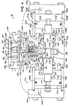
- the right motor chamber 162R With the piston 181 and slide valve 180 shifted to the right, as shown in F ig. 4, and as shown by nondotted flow lines in Fig. 6, the right motor chamber 162R is placed in communication with wet glycol outlet port 175 through communicating ports 163R and 164R, slide valve cavity 177, and passage 176.
- wet glycol is discharged from right motor chamber 162 R when slide valve 180 is shifted to the right.
- Wet glycol it similarly discharged from the left motor chamber 162L when the slide valve 180 is shifted to the left, Fig. 3.
- a toggle 107 is pivotally mounted about a pivot axis as by pin 130 in cavity 171 which opens at the lower portion thereof into central body bore 158.
- the toggle is mounted such that the length of the lever arm 131 formed above the pivot axis is substantially shorter and preferably half or less the length of the lever arm 132 formed ⁇ below the toggle pivot axis.
- the upper end portion of the toggle terminates in a ball portion 133 which is swivally mounted in an open socket position 134 of pilot slide valve 108. Pilot slide valve 108 is biased into planar, slideahle, abutting relationship with an upper planar face of cavity 171 with biasing spring 135.
- Spring 135 is engaged at its lower end with a shoulder portion of toggle 107.
- This mechanical advantage of the toggle also helps assure reliable restarts when the pump is automatically stopped and started during periodic well "stop clocking". Applicant has discovered that providing a mechanical advantage of at least two to one reduces pump friction sufficiently to allow reliable operation of the unit at pump speeds on the order of 2 or 3 strokes per minute whereas prior art pumping units have generally encountered stalling at any pumping speeds below 10 strokes per minute.
- Fig. 2 the actuator piston 181, the slide valve 180, toggle 107 and pilot slide valve 108 are shown in a centered position. In normal pump operation, the centered position of these components is passed through as the components shift, but the components never stop in this position.
- Fig. 3 shows a normal shifted operational position of the pump. The toggle 107 is tilted so that the pilot slide valve 108 is shifted to the left. This permits high pressure, wet glycol from passage 171 to communicate through port 190R and passage 191R to pressure chamber 192R of main slide valve cylinder 182. Similarly, with the toggle and pilot slide valve shifted as shown in Fig.
- low pressure wet glycol in port 175 communicates through port 193 and cavity 194, then through port 191L to pressure chamber 192L allowing exhaust of wet glycol therefrom. Since there is high pressure in chamber 192R on the right side of and low pressure on the left side of main slide valve piston 181, it is shifted to the left as shown in Fig. 3.
- the high pressure wet glycol which fills chamber 162R to drive piston 105R and the high pressure dry glycol pumped from chamber 159 R are not at exactly the same pressure.
- the dry pumped glycol in chamber 159R is at a somewhat higher pressure because of fluid flow line losses and pump friction. Since there is an imbalance of pressures across piston 105R, the greater fluid pressure in chamber 159R must be compensated by using a smaller effective area on the left face of piston 105R than the effective area' used on the right face of piston 105R.
- each piston 105R, 105L has an outwardly directed face 110R, 110L exposed to wet glycol in an interfacing motor chamber 162R, 162L.
- Each piston also has an oppositely positioned face 111R, 111L exposed to dry glycol in an interfacing pumping chamber 159R, 159L.
- the effective piston 105R face 110R area which is exposed to pressure from the fluid in wet glycol (motor) chamber 162R is the full face area of the piston 105R, i.e., the full cross sectional area of chamber 162R.
- piston 105R face 111R which is exposed to pressure from the fluid in dry glycol (pump) chamber 159R is equal to the full face area of the piston 105R less the cross sectional area of the piston shaft journal portion 154.
- Such a difference in effective piston face areas on opposite sides of each piston provides a force imbalance sufficient to overcome friction and flow energy losses to allow pumping of dry glycol to the absorber as explained below.
- ⁇ P d is always greater than ⁇ P W and this difference increases as the pump speed increases.
- the wet glycol pressure differential ⁇ P acts across the piston faces 110L, 110R with areas A W and the dry glycol pressure differential AP d acts across the piston faces 111L, 111R with areas A d .
- the net force acting on the rod 102, piston 105L, 105R assembly may now be written as: where F F is the force of friction caused by the seals 124L, 124R, 127L, 127R and by the periodic engagement of the toggle tang 300. In order to have piston motion Fnet must be greater than zero. Since ⁇ P d is always greater than ⁇ P W , A W must be greater than A d to allow pump operation.
- the resulting volume differential between the wet glycol and dry glycol chambers may cause the pump to draw more driving fluid from the wet glycol sump than can be made up from wet glycol (and entrained gas) alone. In this event, the pump begins to use well gas as a portion of the driving fluid. Such a result should be avoided to the extent possible since all well gas used in this manner reduced the amount of available sale gas and thus decreased the well yield.
- pistons e.g., 2 inches to 4 inches with relatively small stroke lengths, e.g., .75 inches to 1.1 inches and relatively small journal diameters, e.g., .75 inches to 1.2 inches.
- stroke lengths e.g., .75 inches to 1.1 inches
- journal diameters e.g., .75 inches to 1.2 inches.
- piston diameter should always be substantially greater than the journal diameter: a ratio of at least 1.75:1 and preferably greater than 3:1.
- Applicant's unique pump construction also allows the pressure differential between sides of a piston to be easily adjusted in the field such that the pump operates at a speed commensurate with the pressure and temperature requirements at the well head. Adjustment is achieved by providing a plurality of journals 154, 155 having different outer diameters and with a plurality of cylinders 103L, 103R and pistons 105L, 105R having different internal diameters. A pair of journals, each having the same diameter, are inserted in place of an existing journal pair to vary the pumping speed of the pump/motor unit. A larger pair of journals, e.g. Fig. 8, causes a greater force differential between sides of the piston and thus causes faster pumping and increased glycol circulation or operation to lower pressure. A smaller pair of journals, e.g. Fig. 7, reduces pumping speed or increases lower operation pressure and also reduces somewhat the ratio of wet glycol to dry glycol required for pump operation.
- Journal replaceability is provided by the use of a relatively large central body bore diameter 158 with respect to push rod 102 diameter, e.g., 2:1.
- Journal seal assemblies 115, 116, 177, 124, 125 are, of course, provided with a plurality of different internal diameter configurations to accommodate various journal diameters.
- the fine adjustment to operational speed of the pump is preferably controlled by restricting the wet glycol flow in lines 164L and 164R, by use of a conventional flow control device such as a needle valve (not shown).
- a conventional flow control device such as a needle valve (not shown).
- the coarse adjustment of pump speed for a given operating condition i.e., the maximum pump speed limit, is provided by selection of cylinder bore diameter to journal diameter ratio.
Landscapes
- Engineering & Computer Science (AREA)
- Chemical & Material Sciences (AREA)
- Analytical Chemistry (AREA)
- General Chemical & Material Sciences (AREA)
- Oil, Petroleum & Natural Gas (AREA)
- Chemical Kinetics & Catalysis (AREA)
- Mechanical Engineering (AREA)
- General Engineering & Computer Science (AREA)
- Reciprocating Pumps (AREA)
- Drying Of Gases (AREA)
Applications Claiming Priority (2)
| Application Number | Priority Date | Filing Date | Title |
|---|---|---|---|
| US06/661,398 US4588424A (en) | 1984-10-16 | 1984-10-16 | Fluid pumping system |
| US661398 | 1984-10-16 |
Publications (2)
| Publication Number | Publication Date |
|---|---|
| EP0179371A2 true EP0179371A2 (de) | 1986-04-30 |
| EP0179371A3 EP0179371A3 (de) | 1987-09-30 |
Family
ID=24653425
Family Applications (1)
| Application Number | Title | Priority Date | Filing Date |
|---|---|---|---|
| EP85112939A Withdrawn EP0179371A3 (de) | 1984-10-16 | 1985-10-11 | Einrichtung zum Pumpen eines Fluidums |
Country Status (6)
| Country | Link |
|---|---|
| US (1) | US4588424A (de) |
| EP (1) | EP0179371A3 (de) |
| JP (1) | JPS61181518A (de) |
| AU (1) | AU4878985A (de) |
| CA (1) | CA1302376C (de) |
| NO (1) | NO854091L (de) |
Cited By (1)
| Publication number | Priority date | Publication date | Assignee | Title |
|---|---|---|---|---|
| WO1997032127A1 (en) * | 1996-02-26 | 1997-09-04 | T. Smedegaard A/S | Apparatus for use in a liquid circulation system and method for using said apparatus |
Families Citing this family (21)
| Publication number | Priority date | Publication date | Assignee | Title |
|---|---|---|---|---|
| US4676806A (en) * | 1986-03-03 | 1987-06-30 | Alvin Dean | Temperature sensitive control system for liquid motor and pump in a natural gas dehydration system |
| US4689053A (en) * | 1986-03-03 | 1987-08-25 | Heath Rodney T | Heating system with gas jet driven circulation flow for high pressure well head separator |
| US5766313A (en) * | 1994-12-13 | 1998-06-16 | Heath; Rodney T. | Hydrocarbon recovery system |
| US7531030B2 (en) | 1999-06-15 | 2009-05-12 | Heath Rodney T | Natural gas dehydrator and system |
| US6238461B1 (en) | 1999-06-15 | 2001-05-29 | Rodney T. Heath | Natural gas dehydrator |
| US7905722B1 (en) | 2002-02-08 | 2011-03-15 | Heath Rodney T | Control of an adjustable secondary air controller for a burner |
| US20070151292A1 (en) * | 2004-09-22 | 2007-07-05 | Heath Rodney T | Vapor Recovery Process System |
| US9353315B2 (en) * | 2004-09-22 | 2016-05-31 | Rodney T. Heath | Vapor process system |
| US20070186770A1 (en) * | 2004-09-22 | 2007-08-16 | Heath Rodney T | Natural Gas Vapor Recovery Process System |
| US8529215B2 (en) | 2008-03-06 | 2013-09-10 | Rodney T. Heath | Liquid hydrocarbon slug containing vapor recovery system |
| EP2405138B1 (de) * | 2009-01-28 | 2015-03-11 | J.C.R. Van Der Hart Holding B.v. | Pumpvorrichtung |
| JP5227840B2 (ja) * | 2009-02-26 | 2013-07-03 | ダイナエアー株式会社 | 調湿装置 |
| US8864887B2 (en) | 2010-09-30 | 2014-10-21 | Rodney T. Heath | High efficiency slug containing vapor recovery |
| KR101219016B1 (ko) | 2011-05-04 | 2013-01-09 | 주식회사 동산공업 | 고압 이형제 펌프 |
| US9109806B2 (en) * | 2011-08-19 | 2015-08-18 | Tai-Her Yang | Heating/cooling system that utilizes secondary fluid pumped through a heat exchanger by the pressure of a thermal exchange fluid |
| WO2013170190A1 (en) | 2012-05-10 | 2013-11-14 | Heath Rodney T | Treater combination unit |
| US9527786B1 (en) | 2013-03-15 | 2016-12-27 | Rodney T. Heath | Compressor equipped emissions free dehydrator |
| US9291409B1 (en) | 2013-03-15 | 2016-03-22 | Rodney T. Heath | Compressor inter-stage temperature control |
| US9932989B1 (en) | 2013-10-24 | 2018-04-03 | Rodney T. Heath | Produced liquids compressor cooler |
| US11105451B2 (en) | 2017-07-07 | 2021-08-31 | Eaton Intelligent Power Limited | Heat transfer interruption for improved fire resistance/proof performance |
| US12589351B2 (en) * | 2021-02-24 | 2026-03-31 | Voltagrid Llc | Mobile refrigeration unit |
Family Cites Families (13)
| Publication number | Priority date | Publication date | Assignee | Title |
|---|---|---|---|---|
| GB530050A (en) * | 1939-06-02 | 1940-12-04 | Byron Jackson Co | Improvements in or relating to hydraulically actuated pumps |
| US2990910A (en) * | 1957-04-01 | 1961-07-04 | Garman O Kimmell | Apparatus and method for circulating and controlling liquids in gas-liquid systems |
| US3070023A (en) * | 1959-09-28 | 1962-12-25 | Nat Tank Co | Fluid operated pump |
| US3288448A (en) * | 1966-03-08 | 1966-11-29 | Combustion Eng | Gas dehydrator |
| US3541763A (en) * | 1968-05-15 | 1970-11-24 | Olman Heath Co | Gas dehydrator |
| US3741689A (en) * | 1971-08-05 | 1973-06-26 | Rupp Co Warren | Air operated diaphragm pump |
| US4019838A (en) * | 1975-09-03 | 1977-04-26 | Fluck Henry T | Air pressure-actuated double-acting diaphragm pump with means to produce a selected start-up position |
| US4286929A (en) * | 1977-03-23 | 1981-09-01 | Rodney T. Heath | Dual pressure gas motor, and method of operation |
| US4163632A (en) * | 1977-08-10 | 1979-08-07 | Bessie L. Caldwell | Hydraulic pump mechanically interconnected with fluid motor distributors |
| US4198214A (en) * | 1979-01-16 | 1980-04-15 | Heath Rodney T | Method and apparatus for heating a separator |
| US4342572A (en) * | 1981-01-05 | 1982-08-03 | Heath Rodney T | Thermal circulation gas treater |
| US4402652A (en) * | 1981-06-25 | 1983-09-06 | Gerlach Charles R | Liquid motor and pump with a stroke regulating gas motor |
| US4431433A (en) * | 1982-09-14 | 1984-02-14 | Gerlach Charles R | Single stage liquid motor and pump |
-
1984
- 1984-10-16 US US06/661,398 patent/US4588424A/en not_active Expired - Fee Related
-
1985
- 1985-07-26 CA CA000487591A patent/CA1302376C/en not_active Expired - Lifetime
- 1985-10-11 EP EP85112939A patent/EP0179371A3/de not_active Withdrawn
- 1985-10-15 NO NO854091A patent/NO854091L/no unknown
- 1985-10-16 AU AU48789/85A patent/AU4878985A/en not_active Abandoned
- 1985-10-16 JP JP60230927A patent/JPS61181518A/ja active Pending
Cited By (2)
| Publication number | Priority date | Publication date | Assignee | Title |
|---|---|---|---|---|
| WO1997032127A1 (en) * | 1996-02-26 | 1997-09-04 | T. Smedegaard A/S | Apparatus for use in a liquid circulation system and method for using said apparatus |
| US6126413A (en) * | 1996-02-26 | 2000-10-03 | T. Smedegaard A/S | Apparatus for use in liquid circulation system and method for using said apparatus |
Also Published As
| Publication number | Publication date |
|---|---|
| AU4878985A (en) | 1986-04-24 |
| JPS61181518A (ja) | 1986-08-14 |
| NO854091L (no) | 1986-04-17 |
| EP0179371A3 (de) | 1987-09-30 |
| US4588424A (en) | 1986-05-13 |
| CA1302376C (en) | 1992-06-02 |
Similar Documents
| Publication | Publication Date | Title |
|---|---|---|
| US4588424A (en) | Fluid pumping system | |
| US4676806A (en) | Temperature sensitive control system for liquid motor and pump in a natural gas dehydration system | |
| US4431433A (en) | Single stage liquid motor and pump | |
| US4659344A (en) | Liquid motor and pump with a stroke regulating gas motor | |
| US4402652A (en) | Liquid motor and pump with a stroke regulating gas motor | |
| US5073090A (en) | Fluid piston compressor | |
| US7488159B2 (en) | Zero-clearance ultra-high-pressure gas compressor | |
| EP1030971B1 (de) | Kryopumpe | |
| CA1147205A (en) | Tandem long stroke reciprocating mud pump assembly | |
| US4347701A (en) | Power system for land vehicles | |
| WO1986002408A1 (fr) | Compresseur a gaz entraine directement par l'energie thermique | |
| KR102353428B1 (ko) | 열역학적 엔진 | |
| US2698580A (en) | Pump | |
| EP0178348B1 (de) | Durch Wärmezufuhr direkt betriebener Gasverdichter | |
| US2884860A (en) | Apparatus for circulating a liquid in a fluid pressure system | |
| EP0215659A2 (de) | Einen Absorptionskreislauf verwendende Systeme | |
| KR880004833A (ko) | 유량을 조절하고 연속적으로 액체를 교환하는 방법 및 장치 | |
| CA1323991C (en) | Heat engine, refrigeration and heat pump cycles approximating the carnot cycle and apparatus therefor | |
| JP4296060B2 (ja) | 超臨界流体又は亜臨界流体による有機物質等の反応装置 | |
| RU2073792C1 (ru) | Факельная силовая установка | |
| US3611876A (en) | Ultra high-pressure compressible fluid motor | |
| RU2008465C1 (ru) | Силовая установка | |
| US679235A (en) | Air or gas pump. | |
| US689625A (en) | Vapor-generator. | |
| RU1774065C (ru) | Насос с тепловым приводом |
Legal Events
| Date | Code | Title | Description |
|---|---|---|---|
| PUAI | Public reference made under article 153(3) epc to a published international application that has entered the european phase |
Free format text: ORIGINAL CODE: 0009012 |
|
| AK | Designated contracting states |
Kind code of ref document: A2 Designated state(s): AT DE FR GB IT NL SE |
|
| PUAL | Search report despatched |
Free format text: ORIGINAL CODE: 0009013 |
|
| AK | Designated contracting states |
Kind code of ref document: A3 Designated state(s): AT DE FR GB IT NL SE |
|
| STAA | Information on the status of an ep patent application or granted ep patent |
Free format text: STATUS: THE APPLICATION IS DEEMED TO BE WITHDRAWN |
|
| 18D | Application deemed to be withdrawn |
Effective date: 19871103 |