EP0179735A2 - Dispositif d'alignement central de composants de longueurs différentes, transportés sur un convoyeur sans fin, relatif à un signe du chemin du convoyeur sans fin - Google Patents
Dispositif d'alignement central de composants de longueurs différentes, transportés sur un convoyeur sans fin, relatif à un signe du chemin du convoyeur sans fin Download PDFInfo
- Publication number
- EP0179735A2 EP0179735A2 EP85730138A EP85730138A EP0179735A2 EP 0179735 A2 EP0179735 A2 EP 0179735A2 EP 85730138 A EP85730138 A EP 85730138A EP 85730138 A EP85730138 A EP 85730138A EP 0179735 A2 EP0179735 A2 EP 0179735A2
- Authority
- EP
- European Patent Office
- Prior art keywords
- mark
- endless conveyor
- measuring elements
- component
- conveyor
- Prior art date
- Legal status (The legal status is an assumption and is not a legal conclusion. Google has not performed a legal analysis and makes no representation as to the accuracy of the status listed.)
- Withdrawn
Links
- 238000010073 coating (rubber) Methods 0.000 claims description 3
- 239000011248 coating agent Substances 0.000 claims description 2
- 238000000576 coating method Methods 0.000 claims description 2
- 230000005484 gravity Effects 0.000 description 3
- 238000010276 construction Methods 0.000 description 2
- 230000005284 excitation Effects 0.000 description 2
- 230000004913 activation Effects 0.000 description 1
- 230000000875 corresponding effect Effects 0.000 description 1
- 238000010586 diagram Methods 0.000 description 1
- 238000005259 measurement Methods 0.000 description 1
- 238000005096 rolling process Methods 0.000 description 1
Images
Classifications
-
- G—PHYSICS
- G01—MEASURING; TESTING
- G01B—MEASURING LENGTH, THICKNESS OR SIMILAR LINEAR DIMENSIONS; MEASURING ANGLES; MEASURING AREAS; MEASURING IRREGULARITIES OF SURFACES OR CONTOURS
- G01B11/00—Measuring arrangements characterised by the use of optical techniques
- G01B11/02—Measuring arrangements characterised by the use of optical techniques for measuring length, width or thickness
- G01B11/04—Measuring arrangements characterised by the use of optical techniques for measuring length, width or thickness specially adapted for measuring length or width of objects while moving
- G01B11/043—Measuring arrangements characterised by the use of optical techniques for measuring length, width or thickness specially adapted for measuring length or width of objects while moving for measuring length
Definitions
- the invention relates to a device for the central alignment of components of different lengths fed on an endless conveyor to a web mark of the endless conveyor, in particular for the central alignment of frame parts for windows at the transfer point to a stacking machine.
- a known device of this type requires an endless conveyor, which is formed from three conveyor belts, for the central alignment of the supplied components of different lengths to the web mark.
- the horizontally running first conveyor belt there is an obliquely upwardly directed conveyor belt, at the end of which the horizontally running third conveyor belt is connected.
- a supplied component in particular a frame part for windows, is conveyed horizontally via the first conveyor belt, until the leading edge of the component runs onto the second, sloping conveyor belt. The leading edge is then conveyed diagonally upwards on this, the component being lifted off the first, horizontal conveyor belt. The leading edge of the component is then conveyed beyond the end of the second, inclined conveyor belt into the space above the third, horizontal conveyor belt without first touching it.
- the component folds over the upper end of the second, inclined conveyor belt, is lifted off the first, horizontal conveyor belt and then comes with its leading half between the leading edge and the center of gravity on the third horizontal conveyor belt for support.
- the component is aligned in the center with the upper end of the second, inclined conveyor belt, which forms the path mark of the endless conveyor.
- the component is aligned with the center of the web mark and can be pushed off the side of the endless conveyor.
- the known device for the central alignment of the components of different lengths fed on an endless conveyor to a web mark of the endless conveyor requires a lot of construction work due to the necessary three conveyor belts and on the other hand does not allow a precise center alignment of the components to the web mark, since components of greater length in particular only have considerable tolerance deviations and therefore cannot be aligned in the center. Furthermore, due to the inevitable use of conveyor belts, a transverse pushing of the components from the endless conveyor is required.
- the invention is therefore based on the object of enabling a precise central alignment of the components of different lengths fed on an endless conveyor to the path mark of the endless conveyor, the device being intended to be able to be produced in particular with little construction effort.
- the invention provides that measuring elements connected to a control circuit for detecting the position of the components on the longitudinal conveyor are arranged in the longitudinal direction of the endless conveyor in front of and behind the mark and at intervals from each other, that the measuring elements from the leading edge of each component in succession be switched on and that the control circuit switches off the drive of the endless conveyor with the same number of measuring elements switched on in front of and behind the mark as soon as a measuring element located in front of the mark is released from the trailing edge of the component.
- the device according to the invention only requires a single endless conveyor which only extends in a substantially horizontal plane.
- the arrangement of the measuring elements on the endless conveyor namely in front of and behind the web mark and at intervals from one another, as well as the connection of the individual measuring elements with a control circuit makes it possible in a structurally and circuit-technically simple manner that the position of the component conveyed on the endless conveyor is centered on the web mark, which is attached to the endless conveyor, can be quickly determined, the drive of the endless conveyor being switched off at the moment of the central alignment of the component with the web mark via the control circuit.
- a measuring element arranged in front of and behind this at the same distance from the mark forms a pair of measuring elements, the control outputs of which are connected in series to the voltage supply for the drive stop of the endless conveyor, and furthermore is in the control output of each measuring element located behind the mark of each pair of measuring elements, the control input of the measuring element located in front of the pair of measuring elements associated with this, located in front of the mark, is switched.
- the measuring elements are designed as photocells. You can choose to use photocells with or without a reflector.
- the endless conveyor is designed as a roller table with driven rollers, the individual rollers of the roller table being coated with a rubber coating with a high coefficient of friction.
- a roller table can be designed with rollers mounted on only one side, the circulating conveyors of a stacking machine being able to reach between the individual rollers and the two circulating conveyors being arranged symmetrically to the path mark of the endless conveyor designed as a roller conveyor.
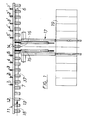
- the device comprises a roller table 11 comprising a carrier 12 and a number of rollers 13 mounted on one side in it.
- the rollers 13 are provided in a manner not shown with a coating of rubber with a high coefficient of friction.
- the one-sided mounting takes place in a known manner in the carrier 12, in which drive chains for the sprockets, not shown, attached to the individual rollers 13 are also guided.
- the drive chains are operated by a drive, also not shown, which is provided with an electrical stop K 213.
- the roller table 11 has a web mark 14 which is arranged in the center of the circulating conveyors 15, 16 of a stacking machine 17.
- the stacking machine 17 can correspond to the stacking machine shown and described in DE-GM 77 24 470, to which express reference is made.
- photocells 1 to 5 and 5 'to 1' serving as measuring elements are arranged in front of and behind the web mark 14 and at intervals from one another.
- the photocells 1 to 5 are arranged in the conveying direction (arrow 18) in front of the web mark 14 and the photocells 5 'to 1' in the conveying direction (arrow 18) behind the web mark 14.
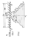
- the photocells 1 to 5 and 5 'to 1' are each arranged above the plane of the individual rollers 13, as is shown in principle in FIG. 2, so that the presence or absence of a component, in particular a frame part for windows, on the roller table 11 can be determined.
- the distance between the photocells 5, 5 'closest to the web mark 14 simultaneously forms the smallest length L min for a component, wherein the distance between the photocells 1 , 1 'furthest away from the web mark 14 indicates the length L max for the greatest length of a component which can be aligned with the web mark 14 with the device.
- FIG 3 shows the position of the components 30 to 37 aligned in the center of the web mark 14 relative to the drivers 15, 16 of the two circulating conveyors of the automatic stacking machine 17. Since the components 30 to 37 are frame parts for windows which have beveled surfaces, the components 30 to 37 must be aligned with the center of gravity S in the mark 14.
- FIG. 1 shows the individual photocells 1 to 5 to the left of the central web mark 14 and 5 'to 1' to the right of the web mark 14, the conveying direction being shown by the arrow 18. The conveying direction thus runs from left to right.
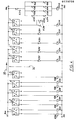
- Each photocell 1 to 5 and 5 'to 1' comprises a connection 300 for the voltage supply, and contacts K 200, K 201 for photocell 1, K 202, K 203 for photocell 2, K 204, K 205 for photocell 3 , K 206, K 207 for photocell 4 and K 208 for photocell 5 as well as one contact K 209 for photocell 5 ', K 210 for photocell 4'., K 211 for photocell 3 ', K 212 for Photocell 2 'and K 214 at photocell 1'.
- the contacts K 200, K202, K204, K 206, K 208, K 209, K 210, K 211, K 212, K 214 are each energized or switched on when the photocell is dark due to a component passing by, ie the photocell contact in the position "D" stands.
- the contacts K 201, K 203, K 205 and K 207 are each full. excited or switched on when the photocells 1 to 5 are not darkened by a passing component, ie are in their switch position "H".
- These control inputs K 207, K 205, K 203 and K 201 are each in the connecting lines of the photocells 5 'to 1'. switched on to their respective control outputs K 209, K 210, K 211, K 212 and K 214.
- the control outputs K 208, K 209; K 206, K 210; K 204, K 211; K 202, K212 and K 200, K214 each lie in series in the voltage supply for the drive stop K 213 of the endless conveyor designed as a rolling element 11, each in the control input K 209, K 210, K 211, K 212, K 214 the photocell 5 ', 4', 3 ', 2', 1 'located at the mark 14: one pair of measuring elements, the control inputs K 207, K 205, K 203, K 201, K 200 before the mark 14 associated with this pair of measuring elements located photocell 4,3, 2,1 is switched.
- the control circuit shown in FIG. 4 operates as follows: The shortest component 30 first passes through the photocells 1 to 5 in the direction of movement (arrow 18), the leading edge 6 of the component 30 moving the photocells from light "H” to dark “D” toggles. As long as the leading edge 6 has not yet reached the photocell 5 'located behind the web mark 14, the photocells 1, 2 and 3 lying in the direction of movement (18) in front of the web mark (14) can even return to their " H " position after passing the Component 30 are switched without the control circuit acting on the drive of the roller table 11. When the photocell 5 'is reached by the leading edge 6 , the photocell 5' is switched to its dark "D" position.
- the photocell 5 is also switched to the dark "D" position, so that the contact K 208 is excited.
- the photocell 4 is switched to its bright "H” position and the contact K 207 is excited.
- This enables contact as well K 209 of the photocell 5 'is excited so that the two contacts K 208 and K 209 connected in series can apply voltage from the voltage source 300 to the stop K 213 for driving the roller table 11, which thus suddenly stops the roller table 11.
- a slipping of the component 30 on the rollers 13 of the roller table 11 is prevented by the rubber coating of the rollers 13.
- the component 30 thus comes to a standstill with its trailing edge at the level of the photocell 4, as shown in FIGS. 2 and 3.
- the control circuit has a corresponding effect on component 34, the leading edge of which passes to photocell 3 'via web mark 14 until photocell 2 switches over in its "H" position.
- the output contact K 203 is excited. This enables excitation of the output contact K 211 of the photocell 3 '.
- the contact K 204 of the photocell 3 of this pair of measuring elements is excited so that the voltage 300 can in turn be applied to the stop contact K 213 for the roller table 11 by the contacts K 204 and K 211 connected in series.
- a component of a length which is greater than L max is conveyed over the roller table 11, this component causes the end photocells 1 and 1 'to be dark “D" in their position at the same time.
- the contact K 200 then switched on or excited enables the contact K 214 of the photocell 1 ′ to be switched on or opened and thus signals the excess length of a component.
- Such a component can either be moved out of the roller table 11 without a stop or can result in a stop of the roller table 11 and, at the same time, a standstill of the automatic stacking device 17.
- the activation or excitation of the contact K 213, in addition to the setting of the roller table 11, causes the drivers 15, 16 of the automatic stacking device 17 to start in order to feed the component 30 to 37, which is centered on the roller table 11, to the stack 19 to be formed.
Landscapes
- Physics & Mathematics (AREA)
- General Physics & Mathematics (AREA)
- Delivering By Means Of Belts And Rollers (AREA)
- Attitude Control For Articles On Conveyors (AREA)
- Control Of Conveyors (AREA)
Applications Claiming Priority (2)
| Application Number | Priority Date | Filing Date | Title |
|---|---|---|---|
| DE19843438835 DE3438835C1 (de) | 1984-10-20 | 1984-10-20 | Vorrichtung zum mittigen Ausrichten von auf einem Endlosfoerderer zugefuehrten Bauteilen unterschiedlicher Laenge zu einer Bahnmarke des Endlosfoerderers |
| DE3438835 | 1984-10-20 |
Publications (2)
| Publication Number | Publication Date |
|---|---|
| EP0179735A2 true EP0179735A2 (fr) | 1986-04-30 |
| EP0179735A3 EP0179735A3 (fr) | 1987-04-15 |
Family
ID=6248595
Family Applications (1)
| Application Number | Title | Priority Date | Filing Date |
|---|---|---|---|
| EP85730138A Withdrawn EP0179735A3 (fr) | 1984-10-20 | 1985-10-10 | Dispositif d'alignement central de composants de longueurs différentes, transportés sur un convoyeur sans fin, relatif à un signe du chemin du convoyeur sans fin |
Country Status (4)
| Country | Link |
|---|---|
| EP (1) | EP0179735A3 (fr) |
| JP (1) | JPS61101311A (fr) |
| DE (1) | DE3438835C1 (fr) |
| DK (1) | DK470185A (fr) |
Cited By (2)
| Publication number | Priority date | Publication date | Assignee | Title |
|---|---|---|---|---|
| US8125651B2 (en) | 2008-01-28 | 2012-02-28 | Panasonic Corporation | Substrate detection device and substrate conveyance apparatus |
| CN104215169A (zh) * | 2014-08-22 | 2014-12-17 | 中冶天工上海十三冶建设有限公司 | 一种辊道中心线快速定位工具及其使用方法 |
Families Citing this family (1)
| Publication number | Priority date | Publication date | Assignee | Title |
|---|---|---|---|---|
| DE3538209C1 (en) * | 1985-10-23 | 1987-05-07 | Schiepe Stapelautomaten Gmbh | Apparatus for the centred alignment of components of different lengths fed on an endless conveyor in relation to a pathmark of the endless conveyor |
Family Cites Families (5)
| Publication number | Priority date | Publication date | Assignee | Title |
|---|---|---|---|---|
| JPS497960B1 (fr) * | 1969-09-01 | 1974-02-23 | ||
| DD108953A1 (fr) * | 1973-12-20 | 1974-10-12 | ||
| JPS533140A (en) * | 1976-06-30 | 1978-01-12 | Fujitsu Ltd | Data transfer system |
| DE3404148A1 (de) * | 1983-03-01 | 1984-10-31 | Karl 7519 Zaisenhausen Sicko | Vorrichtung zum aufreihen oder stapeln von laenglichen gegenstaenden |
| DE3316089A1 (de) * | 1983-05-03 | 1984-11-08 | Martin Ing.(grad.) 4502 Bad Rothenfelde Lieske | Schaltungsanordnung zur exakten endlagenbestimmung eines gegenstandes zur mittenausrichtung |
-
1984
- 1984-10-20 DE DE19843438835 patent/DE3438835C1/de not_active Expired
-
1985
- 1985-10-10 EP EP85730138A patent/EP0179735A3/fr not_active Withdrawn
- 1985-10-15 DK DK470185A patent/DK470185A/da not_active Application Discontinuation
- 1985-10-18 JP JP23313685A patent/JPS61101311A/ja active Pending
Cited By (2)
| Publication number | Priority date | Publication date | Assignee | Title |
|---|---|---|---|---|
| US8125651B2 (en) | 2008-01-28 | 2012-02-28 | Panasonic Corporation | Substrate detection device and substrate conveyance apparatus |
| CN104215169A (zh) * | 2014-08-22 | 2014-12-17 | 中冶天工上海十三冶建设有限公司 | 一种辊道中心线快速定位工具及其使用方法 |
Also Published As
| Publication number | Publication date |
|---|---|
| DK470185A (da) | 1986-04-21 |
| JPS61101311A (ja) | 1986-05-20 |
| DE3438835C1 (de) | 1986-02-27 |
| DK470185D0 (da) | 1985-10-15 |
| EP0179735A3 (fr) | 1987-04-15 |
Similar Documents
| Publication | Publication Date | Title |
|---|---|---|
| DE2358185C2 (de) | Sortiergerät mit Vereinzelungsbahn und Sortierbahn | |
| DE2808617C2 (de) | Verfahren und Anlage zum Ausrichten von stapel- oder reihenförmigen Gruppen von Gegenständen | |
| DD215985A5 (de) | Vorrichtung zum beschicken und einwickeln von erzeugnissen | |
| EP1464595A2 (fr) | Système de transport de conteneurs, en particulier un tapis de transport de valises pour aéroport | |
| DE2614659C3 (de) | Bandförderweiche | |
| CH665410A5 (de) | Vorrichtung zum beschicken einer verarbeitungseinrichtung fuer biegsame, flaechige erzeugnisse, insbesondere druckprodukte. | |
| DE2242993C3 (de) | Transportriementrieb | |
| DE2646342A1 (de) | Vorrichtung zum trennen einer endlosbahn in einzelstuecke entlang von schwaechungslinien | |
| DE3438835C1 (de) | Vorrichtung zum mittigen Ausrichten von auf einem Endlosfoerderer zugefuehrten Bauteilen unterschiedlicher Laenge zu einer Bahnmarke des Endlosfoerderers | |
| DE1912150A1 (de) | Verfahren und Bogenkaschiermaschine zum Zufuehren der Kaschiersaetze zur Presswalze | |
| DE2232610C2 (de) | Ketteneinrichtung zu einer Förderanlage für papierverarbeitende Betriebe | |
| EP1498353A1 (fr) | Machine pour l'emballage | |
| EP0128352B1 (fr) | Dispositif de transport et d'empilage de feuilles | |
| DE2940014C2 (de) | Vorrichtung zum Quertransport | |
| DE3308069A1 (de) | Vorrichtung zum zusammenfuehren von teilbahnen ueber umlenkwalzen in eine gemeinsame ebene | |
| DE3214600C2 (fr) | ||
| EP1247775B1 (fr) | Plieuse pour les produits imprimés | |
| DE3245981A1 (de) | Verfahren und vorrichtung zum drehen von auf einem foerderer transportierten gegenstaenden um ihre hochachse aus einer anfangs- in eine endstelle | |
| DE3538209C1 (en) | Apparatus for the centred alignment of components of different lengths fed on an endless conveyor in relation to a pathmark of the endless conveyor | |
| EP0000366A1 (fr) | Dispositif d'alimentation en feuilles | |
| DE19948704C1 (de) | Vorrichtung zum Drehen eines Papierstapels | |
| DE2202069A1 (de) | Sortiermaschine fuer Poststuecke,Dokumente u.dgl.,und Transportvorrichtung hierfuer | |
| DE3243950C2 (de) | Vereinzelungseinrichtung für die Vereinzelung von Brettern oder dgl. | |
| DE3401233C2 (fr) | ||
| DE19725605A1 (de) | Verfahren und Vorrichtung zur Herstellung von mit Beilagen versehenen Falzexemplaren |
Legal Events
| Date | Code | Title | Description |
|---|---|---|---|
| PUAI | Public reference made under article 153(3) epc to a published international application that has entered the european phase |
Free format text: ORIGINAL CODE: 0009012 |
|
| AK | Designated contracting states |
Kind code of ref document: A2 Designated state(s): AT BE CH DE FR GB IT LI LU NL SE |
|
| PUAL | Search report despatched |
Free format text: ORIGINAL CODE: 0009013 |
|
| AK | Designated contracting states |
Kind code of ref document: A3 Designated state(s): AT BE CH DE FR GB IT LI LU NL SE |
|
| STAA | Information on the status of an ep patent application or granted ep patent |
Free format text: STATUS: THE APPLICATION HAS BEEN WITHDRAWN |
|
| 18W | Application withdrawn |
Withdrawal date: 19870622 |
|
| RIN1 | Information on inventor provided before grant (corrected) |
Inventor name: PFEIFFER, ULRICH |