EP0180041A2 - Flan unitaire en matériau pliable pour former un casier divisible - Google Patents
Flan unitaire en matériau pliable pour former un casier divisible Download PDFInfo
- Publication number
- EP0180041A2 EP0180041A2 EP85112285A EP85112285A EP0180041A2 EP 0180041 A2 EP0180041 A2 EP 0180041A2 EP 85112285 A EP85112285 A EP 85112285A EP 85112285 A EP85112285 A EP 85112285A EP 0180041 A2 EP0180041 A2 EP 0180041A2
- Authority
- EP
- European Patent Office
- Prior art keywords
- perforated plate
- longitudinal
- crate
- side walls
- support tabs
- Prior art date
- Legal status (The legal status is an assumption and is not a legal conclusion. Google has not performed a legal analysis and makes no representation as to the accuracy of the status listed.)
- Granted
Links
- 239000000463 material Substances 0.000 title claims abstract description 4
- 239000000853 adhesive Substances 0.000 claims description 10
- 230000001070 adhesive effect Effects 0.000 claims description 10
- 238000005452 bending Methods 0.000 claims description 7
- 230000003313 weakening effect Effects 0.000 claims description 6
- 240000004282 Grewia occidentalis Species 0.000 description 1
- 238000004026 adhesive bonding Methods 0.000 description 1
- 238000010276 construction Methods 0.000 description 1
Images

Classifications
-
- B—PERFORMING OPERATIONS; TRANSPORTING
- B65—CONVEYING; PACKING; STORING; HANDLING THIN OR FILAMENTARY MATERIAL
- B65D—CONTAINERS FOR STORAGE OR TRANSPORT OF ARTICLES OR MATERIALS, e.g. BAGS, BARRELS, BOTTLES, BOXES, CANS, CARTONS, CRATES, DRUMS, JARS, TANKS, HOPPERS, FORWARDING CONTAINERS; ACCESSORIES, CLOSURES, OR FITTINGS THEREFOR; PACKAGING ELEMENTS; PACKAGES
- B65D71/00—Bundles of articles held together by packaging elements for convenience of storage or transport, e.g. portable segregating carrier for plural receptacles such as beer cans or pop bottles; Bales of material
- B65D71/70—Trays provided with projections or recesses in order to assemble multiple articles, e.g. intermediate elements for stacking
- B65D71/72—Trays provided with projections or recesses in order to assemble multiple articles, e.g. intermediate elements for stacking formed by folding one or more blanks, the articles being inserted in openings in a wall
Definitions
- the invention relates to a one-piece blank made of foldable material for a divisible tray, consisting of a bottom to which opposite end and side walls are articulated, of which the side walls each have a recess on their longitudinal edge facing away from the floor for the position-secure reception of containers or the like Wear the perforated plate provided, the width of which corresponds to approximately half the floor width, and the cover support flaps which can be folded by 90 ° in their longitudinal edge area facing away from the side wall, while a tear strip is provided in the center of the end walls, which are aligned with one another and with a cross-sectional weakening running centrally through the floor .
- lid support tabs are glued to the box bottom by means of folds bent at right angles, which, aligned with the lid support tabs, has a cross-sectional weakening in the form of a perforation which merges into the tear strips mentioned in the end walls of the crate.
- the lid support tabs of a perforated plate engage in punched holes in the other perforated plate, so that a kind of Ver toothing arises.
- the lid support flaps of one perforated plate are glued to the box bottom on opposite sides by means of folds which are connected to one another via a cross-sectional weakening.
- the fold of one row of the cover support tabs is glued to the fold of the other cover support tabs, these other cover support tabs being designed in the form of a continuous support web.
- This previously known tray is designed in the form of an erection box with four-corner gluing, the side walls in each case forming stacks in their end region.
- the end walls have a greater height than the side walls.
- the object of the invention is to improve the divisibility and the rigidity of these previously known crates.
- the tear strips merge into a longitudinal longitudinal slit forming the cross-section weakening, from which two fastening strips for the lid support flaps which are bendable in opposite directions are punched out, the height of which corresponds approximately to that of the side walls.
- the tear strips extend with a section into the floor.
- an adhesive flap is articulated on the front edges of each perforated plate, and that the front and side walls have the same height.
- floor support tabs are punched out of the floor, which can be folded by 90 ° about a bending line, and whose height corresponds approximately to that of the end or side walls, the end of each floor support tab opposite the bending line providing a support surface for the perforated plate as well as one yourself extending hook-shaped portion, for which a locking slot is provided in the perforated plate.
- each hook-shaped section of a floor support bracket with a rounded head protrudes through the trapezoidal locking slot in the perforated plate, bears against its shorter parallel side and rests on the perforated plate with a retainer.
- These floor support tabs are preferably at right angles to the cover support tabs or the fastening strips.
- lid support tabs are glued to the side of the assigned fastening strip facing away from the longitudinal longitudinal slot, as a result of which the lid support tabs are always supported on the bottom of the crate. This connection is not affected when the crate is divided.
- the width of the perforated plates is preferably somewhat larger than half the base width, so that the two perforated plates overlap somewhat in the central longitudinal region. It is advantageous if in this overlap area the free longitudinal edge of the bottom! The perforated plate rests on the cover support tabs of the upper perforated plate, since this further increases the strength. If this overlap area is made somewhat narrower than the longitudinal longitudinal slit, the two opposite cover support tabs are inclined slightly towards one another upwards, so that there is also a high degree of stability.
- the tear strip is preferably located directly between two adhesive tabs, the perforated plates in the region of the tear strip each being able to form an engagement opening. This makes handling easier, while the tear strips prevent the end walls from being accidentally torn open.
- the divisibility is designed such that after the division, each crate half maintains its stability, so that the division results in two compact crates.
- the division of the crate is very easy to carry out, since the tear strips can only be made very short. Nevertheless, due to its construction, the tray has an extraordinarily strong torsional stiffness and can therefore also cope with extreme loads.
- Conventional passage openings can be provided in the bottom of the tray, which enables the tray to be erected mechanically on the erecting machines on the market.
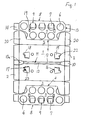
- the stamped blank comprises a base 1, to which opposite end walls 2 and side walls 3 of the same height are articulated.
- a perforated plate 5 is articulated in each case, the recesses 6 or the like for accommodating containers in a secure position. has and whose width is slightly larger than half the floor width.
- each perforated plate 5 ten recesses 6 are provided in each perforated plate 5, a cover support flap 7 being punched out of each of the three central recesses 6 located at the free edge region, and around a bending line 9 arranged parallel to the free longitudinal edge 8 of the perforated plate 5 and at a short distance therefrom is bendable by 90 °.
- the height of each lid support bracket 7 corresponds approximately to that of the front or side wall 2, 3.
- a tear strip 10 is provided in the center of each of the two end walls 2, which extends with a short section 10a into the bottom 1, where the bottom section 10a then merges into a bottom longitudinal slot 11. From this longitudinal longitudinal slot 11, two fastening strips 12, which can be bent in opposite directions by 90 ° in each case, are punched out for the cover support tabs 7.
- the bottom longitudinal slot 11 is narrower than the tear strips 10, so that their bottom portions 10a taper in a wedge shape towards the bottom longitudinal slot 11.
- each perforated plate 5 On the front edges 13 of each perforated plate 5, an adhesive tab 14 is articulated.
- Bottom support flaps 15 are punched out of the base 1, which can be folded through a bending line 16 by 90 ° and whose height corresponds approximately to that of the end or side walls 2, 3.
- the end of each floor support bracket 15 opposite the bending line 16 has a support surface 17 for the perforated plate 5 and a hook-shaped section 18 extending beyond it, for which a locking slot 19 is provided in the perforated plate 5, which has approximately the shape of a trapezoid.
- the side walls 3 form stack supports 20 in their end region, as can be seen in particular in FIG. 2.
- the lower ends of the cover support tabs 7 of each perforated plate 5 are each glued to the side of the fastening strip 12 which is bent upward and lies below the assigned perforated plate 5 and faces away from the longitudinal longitudinal slot 11.
- the adhesive tabs 14 articulated on the end edges 13 of the perforated plates 5 overlap the end walls 12 and are glued to the outside thereof.
- the two perforated plates 5 overlap in the central longitudinal region and lie here loosely one on top of the other, the free longitudinal edge of the lower perforated plate 5 abutting the cover support tabs 7 of the other perforated plate 5.
- This overlap region 21 of the two perforated plates 5 is somewhat narrower than the longitudinal bottom slot 11, so that the two opposite cover support tabs 7 are inclined slightly upwards towards one another and thus form the shape of a blunt wedge.
- Each hook-shaped section 18 of a base support bracket 15 projects with a rounded head 22 through the trapezoidal shape Deten locking slot 19 in the perforated plate 5, lies against its shorter parallel side and rests on the perforated plate 5 with a retainer 23.
- two floor support brackets 15 are provided in each floor half, each of which is at right angles to the cover support brackets 7 or the fastening strips 12.
- the tear strip 10 lies directly between two adhesive tabs 14, the perforated plates 5 each forming an engagement opening 24 in the region of the tear strip 10.
Landscapes
- Engineering & Computer Science (AREA)
- Mechanical Engineering (AREA)
- Cartons (AREA)
- Pallets (AREA)
- Floor Finish (AREA)
Priority Applications (1)
| Application Number | Priority Date | Filing Date | Title |
|---|---|---|---|
| AT85112285T ATE32688T1 (de) | 1984-11-02 | 1985-09-27 | Einstueckiger zuschnitt aus faltbarem material fuer eine teilbare steige. |
Applications Claiming Priority (2)
| Application Number | Priority Date | Filing Date | Title |
|---|---|---|---|
| DE8432049U | 1984-11-02 | ||
| DE8432049U DE8432049U1 (de) | 1984-11-02 | 1984-11-02 | Einstueckiger Zuschnitt aus faltbarem Material fuer eine teilbare Steige |
Publications (3)
| Publication Number | Publication Date |
|---|---|
| EP0180041A2 true EP0180041A2 (fr) | 1986-05-07 |
| EP0180041A3 EP0180041A3 (en) | 1986-12-17 |
| EP0180041B1 EP0180041B1 (fr) | 1988-03-02 |
Family
ID=6772283
Family Applications (1)
| Application Number | Title | Priority Date | Filing Date |
|---|---|---|---|
| EP85112285A Expired EP0180041B1 (fr) | 1984-11-02 | 1985-09-27 | Flan unitaire en matériau pliable pour former un casier divisible |
Country Status (4)
| Country | Link |
|---|---|
| EP (1) | EP0180041B1 (fr) |
| AT (1) | ATE32688T1 (fr) |
| DE (2) | DE8432049U1 (fr) |
| PT (1) | PT81379B (fr) |
Families Citing this family (1)
| Publication number | Priority date | Publication date | Assignee | Title |
|---|---|---|---|---|
| DE8601439U1 (de) * | 1986-01-22 | 1986-02-27 | Badische Karton- Und Pappenfabrik Zweigwerk Der Herzberger Papierfabrik Ludwig Osthushenrich Gmbh & Co Kg, 7562 Gernsbach | Steige aus einem faltbaren Zuschnitt |
Family Cites Families (5)
| Publication number | Priority date | Publication date | Assignee | Title |
|---|---|---|---|---|
| NL7107873A (fr) * | 1970-10-17 | 1972-04-19 | ||
| DE2242371C3 (de) * | 1972-08-29 | 1980-01-24 | Badische Karton- Und Pappenfabrik Zweigwerk Der Herzberger Papierfabrik Ludwig Osthushenrich Kg, 7565 Obertsrot | Steige aus Vollpappe |
| CH548909A (de) * | 1973-06-15 | 1974-05-15 | Cartonnagen Ag | Aufrichteschachtel. |
| DE8319571U1 (de) * | 1983-07-07 | 1984-01-12 | Herzberger Papierfabrik Ludwig Osthushenrich Gmbh & Co Kg, 3420 Herzberg | Zuschnitt fuer eine Steige und daraus hergestellte Steige |
| GB2145695B (en) * | 1983-09-01 | 1987-07-29 | Mead Corp | Divisible article tray |
-
1984
- 1984-11-02 DE DE8432049U patent/DE8432049U1/de not_active Expired
-
1985
- 1985-09-27 DE DE8585112285T patent/DE3561707D1/de not_active Expired
- 1985-09-27 AT AT85112285T patent/ATE32688T1/de active
- 1985-09-27 EP EP85112285A patent/EP0180041B1/fr not_active Expired
- 1985-10-25 PT PT81379A patent/PT81379B/pt not_active IP Right Cessation
Also Published As
| Publication number | Publication date |
|---|---|
| EP0180041B1 (fr) | 1988-03-02 |
| PT81379A (de) | 1985-11-01 |
| DE8432049U1 (de) | 1985-03-07 |
| ATE32688T1 (de) | 1988-03-15 |
| EP0180041A3 (en) | 1986-12-17 |
| DE3561707D1 (en) | 1988-04-07 |
| PT81379B (pt) | 1987-09-18 |
Similar Documents
| Publication | Publication Date | Title |
|---|---|---|
| DE69702930T2 (de) | Kartonschachtel mit zentrierlaschen und zuschnitt für ihre herstellung | |
| DE69004564T2 (de) | Ausgestanzte Kartonplatte zur Aufnahme und Schaustellung von Süssigkeiten und ähnlichen Produkten. | |
| DE2824077C2 (de) | Faltschachtel | |
| DE4003104A1 (de) | Verpackungsbehaelter, insbesondere zur aufnahme von schokoladenartikeln, und zuschnitt zur bildung desselben | |
| DE29618895U1 (de) | Faltschachtel, insbesondere zur Aufbewahrung von Hygieneartikeln | |
| DE2105440C3 (de) | Schaukarton für zerbrechliche Gegenstände, insbesondere Eier | |
| EP0180041B1 (fr) | Flan unitaire en matériau pliable pour former un casier divisible | |
| DE3321614C2 (de) | Stapelfähige Aufrichteschachtel und Zuschnitt hierfür | |
| EP0234234A2 (fr) | Cageot formé à partir d'un flan repliable | |
| EP0177911B1 (fr) | Flan préplié en une seule pièce formé d'un matériau pliable comme le carton, le carton ondulé ou analogue, ledit flan servant à la formation d'un plateau de groupement pour gobelets de section carrée ou rectangulaire | |
| DE7536839U (de) | Aufrichteschachtel | |
| EP0131066B1 (fr) | Flan et plateau réalisé à partir de ce flan | |
| DE20220230U1 (de) | Verpackung | |
| EP0550730B1 (fr) | Boite pliante | |
| DE3326479C2 (de) | Brieflocher | |
| DE19747420A1 (de) | Auffaltbarer, einstückiger Zuschnitt für einen Pizzabehälter | |
| DE9217601U1 (de) | Stülpschachtel aus Pappe, insbesondere Wellpappe | |
| DE19638308B4 (de) | Faltschachtel | |
| DE29509021U1 (de) | Steige, insbesondere für Obst und Gemüse | |
| DE3525456C2 (fr) | ||
| EP0316890B1 (fr) | Flan d'une seule pièce, préplié en matière pliable pour casier à gobelets | |
| EP0340319A1 (fr) | Boîte pliante | |
| EP0328509A1 (fr) | Flan pour une caisse en carton, en particulier en carton ondulé | |
| EP0386280A1 (fr) | Flan de matériel plat | |
| DE7703885U1 (de) | Steige |
Legal Events
| Date | Code | Title | Description |
|---|---|---|---|
| PUAI | Public reference made under article 153(3) epc to a published international application that has entered the european phase |
Free format text: ORIGINAL CODE: 0009012 |
|
| AK | Designated contracting states |
Kind code of ref document: A2 Designated state(s): AT CH DE FR GB IT LI NL |
|
| ITCL | It: translation for ep claims filed |
Representative=s name: MODIANO & ASSOCIATI S.R.L. |
|
| PUAL | Search report despatched |
Free format text: ORIGINAL CODE: 0009013 |
|
| EL | Fr: translation of claims filed | ||
| TCNL | Nl: translation of patent claims filed | ||
| AK | Designated contracting states |
Kind code of ref document: A3 Designated state(s): AT CH DE FR GB IT LI NL |
|
| 17P | Request for examination filed |
Effective date: 19861204 |
|
| 17Q | First examination report despatched |
Effective date: 19870805 |
|
| GRAA | (expected) grant |
Free format text: ORIGINAL CODE: 0009210 |
|
| AK | Designated contracting states |
Kind code of ref document: B1 Designated state(s): AT CH DE FR GB IT LI NL |
|
| REF | Corresponds to: |
Ref document number: 32688 Country of ref document: AT Date of ref document: 19880315 Kind code of ref document: T |
|
| GBT | Gb: translation of ep patent filed (gb section 77(6)(a)/1977) | ||
| REF | Corresponds to: |
Ref document number: 3561707 Country of ref document: DE Date of ref document: 19880407 |
|
| ET | Fr: translation filed | ||
| ITF | It: translation for a ep patent filed | ||
| PLBE | No opposition filed within time limit |
Free format text: ORIGINAL CODE: 0009261 |
|
| STAA | Information on the status of an ep patent application or granted ep patent |
Free format text: STATUS: NO OPPOSITION FILED WITHIN TIME LIMIT |
|
| 26N | No opposition filed | ||
| PGFP | Annual fee paid to national office [announced via postgrant information from national office to epo] |
Ref country code: GB Payment date: 19900907 Year of fee payment: 6 |
|
| PGFP | Annual fee paid to national office [announced via postgrant information from national office to epo] |
Ref country code: FR Payment date: 19900914 Year of fee payment: 6 |
|
| PGFP | Annual fee paid to national office [announced via postgrant information from national office to epo] |
Ref country code: CH Payment date: 19900927 Year of fee payment: 6 |
|
| PGFP | Annual fee paid to national office [announced via postgrant information from national office to epo] |
Ref country code: AT Payment date: 19900928 Year of fee payment: 6 |
|
| ITTA | It: last paid annual fee | ||
| PGFP | Annual fee paid to national office [announced via postgrant information from national office to epo] |
Ref country code: NL Payment date: 19900930 Year of fee payment: 6 |
|
| PG25 | Lapsed in a contracting state [announced via postgrant information from national office to epo] |
Ref country code: GB Effective date: 19910927 Ref country code: AT Effective date: 19910927 |
|
| PG25 | Lapsed in a contracting state [announced via postgrant information from national office to epo] |
Ref country code: LI Effective date: 19910930 Ref country code: CH Effective date: 19910930 |
|
| PG25 | Lapsed in a contracting state [announced via postgrant information from national office to epo] |
Ref country code: NL Effective date: 19920401 |
|
| NLV4 | Nl: lapsed or anulled due to non-payment of the annual fee | ||
| GBPC | Gb: european patent ceased through non-payment of renewal fee | ||
| PG25 | Lapsed in a contracting state [announced via postgrant information from national office to epo] |
Ref country code: FR Effective date: 19920529 |
|
| REG | Reference to a national code |
Ref country code: CH Ref legal event code: PL |
|
| REG | Reference to a national code |
Ref country code: FR Ref legal event code: ST |
|
| PGFP | Annual fee paid to national office [announced via postgrant information from national office to epo] |
Ref country code: DE Payment date: 19940914 Year of fee payment: 10 |
|
| PG25 | Lapsed in a contracting state [announced via postgrant information from national office to epo] |
Ref country code: DE Effective date: 19960601 |