EP0180066A2 - Système de communication à modem à branchements multiples - Google Patents
Système de communication à modem à branchements multiples Download PDFInfo
- Publication number
- EP0180066A2 EP0180066A2 EP85112691A EP85112691A EP0180066A2 EP 0180066 A2 EP0180066 A2 EP 0180066A2 EP 85112691 A EP85112691 A EP 85112691A EP 85112691 A EP85112691 A EP 85112691A EP 0180066 A2 EP0180066 A2 EP 0180066A2
- Authority
- EP
- European Patent Office
- Prior art keywords
- modem
- remote
- microprocessor
- master
- data
- Prior art date
- Legal status (The legal status is an assumption and is not a legal conclusion. Google has not performed a legal analysis and makes no representation as to the accuracy of the status listed.)
- Withdrawn
Links
Images


Classifications
-
- H—ELECTRICITY
- H04—ELECTRIC COMMUNICATION TECHNIQUE
- H04L—TRANSMISSION OF DIGITAL INFORMATION, e.g. TELEGRAPHIC COMMUNICATION
- H04L12/00—Data switching networks
- H04L12/28—Data switching networks characterised by path configuration, e.g. LAN [Local Area Networks] or WAN [Wide Area Networks]
- H04L12/40—Bus networks
- H04L12/403—Bus networks with centralised control, e.g. polling
-
- H—ELECTRICITY
- H04—ELECTRIC COMMUNICATION TECHNIQUE
- H04L—TRANSMISSION OF DIGITAL INFORMATION, e.g. TELEGRAPHIC COMMUNICATION
- H04L12/00—Data switching networks
- H04L12/28—Data switching networks characterised by path configuration, e.g. LAN [Local Area Networks] or WAN [Wide Area Networks]
- H04L12/40—Bus networks
- H04L12/40006—Architecture of a communication node
- H04L12/40032—Details regarding a bus interface enhancer
-
- H—ELECTRICITY
- H04—ELECTRIC COMMUNICATION TECHNIQUE
- H04L—TRANSMISSION OF DIGITAL INFORMATION, e.g. TELEGRAPHIC COMMUNICATION
- H04L25/00—Baseband systems
- H04L25/02—Details ; arrangements for supplying electrical power along data transmission lines
- H04L25/03—Shaping networks in transmitter or receiver, e.g. adaptive shaping networks
- H04L25/03006—Arrangements for removing intersymbol interference
- H04L25/03012—Arrangements for removing intersymbol interference operating in the time domain
- H04L25/03114—Arrangements for removing intersymbol interference operating in the time domain non-adaptive, i.e. not adjustable, manually adjustable, or adjustable only during the reception of special signals
- H04L25/03133—Arrangements for removing intersymbol interference operating in the time domain non-adaptive, i.e. not adjustable, manually adjustable, or adjustable only during the reception of special signals with a non-recursive structure
-
- H—ELECTRICITY
- H04—ELECTRIC COMMUNICATION TECHNIQUE
- H04L—TRANSMISSION OF DIGITAL INFORMATION, e.g. TELEGRAPHIC COMMUNICATION
- H04L25/00—Baseband systems
- H04L25/02—Details ; arrangements for supplying electrical power along data transmission lines
- H04L25/03—Shaping networks in transmitter or receiver, e.g. adaptive shaping networks
- H04L25/03006—Arrangements for removing intersymbol interference
- H04L25/03343—Arrangements at the transmitter end
-
- H—ELECTRICITY
- H04—ELECTRIC COMMUNICATION TECHNIQUE
- H04L—TRANSMISSION OF DIGITAL INFORMATION, e.g. TELEGRAPHIC COMMUNICATION
- H04L25/00—Baseband systems
- H04L25/02—Details ; arrangements for supplying electrical power along data transmission lines
- H04L25/03—Shaping networks in transmitter or receiver, e.g. adaptive shaping networks
- H04L25/03006—Arrangements for removing intersymbol interference
- H04L2025/03777—Arrangements for removing intersymbol interference characterised by the signalling
- H04L2025/03802—Signalling on the reverse channel
- H04L2025/03808—Transmission of equaliser coefficients
Definitions
- the present invention relates to synchronous modem communication systems, and more particularly to high-speed multidrop polling communication systems.
- a frequent embodiment of modem communication systems combines a single master modem connected to the related data terminal equipment (DTE) and a plurality of remote modems, each having their own DTE.
- the master modem under control of the corresponding DTE, will poll the remote DTE through the corresponding remote modems, one at a time.
- the polling is accomplished by sending an address code which the associated remote DTE will recognize and provide a request to send (RTS) signal to the remote modem, whereupon the remote modem will signal the master modem by returning an acknowledgement signal.
- RTS request to send
- each modem typically including internal line equalizer, must be optimized to provide the maximum data flow and minimum signal errors within the exchange of data. This is usually accomplished by preceding the data exchange with a training sequence of predetermined signals and adjusting the modem to maximize the accuracy of those predetermined signals.
- the modem system is used for polling of remote systems where the length of the data to be exchanged is rather short.
- the time necessary to equalize and adjust the respective communicating modems often exceeds the length of time of the exchange data itself. Under such conditions, the communication system becomes significantly underused, and inefficient. Further increase in data communication speed requires still further or extended equalization adjustment time periods. As a result, the improvement in modem data transfer speed is reduced by the initial modem training sequence, thereby eliminating the advantage of high-speed modems in many applications.
- the high-speed multidrop polling communication system provides a communication system including a master modem and a plurality of remote or slave modems having transmit equalizers which pre-equalize the signals transmitted over the data channel.
- the transmitter pre-equalizers include storage means wherein the coefficients used, once selected during an initial long train start-up sequence, are retained. Thereafter, the slave modems reapply the transmit equalization coefficients associated with the particular channel, together with a short "fast" training sequence for fine adjustment of the communicating modems.
- the present invention provides for an initial long-train start-up sequence of 2.4 seconds, during which the equalizer coefficients of a remote-to-master channel are acquired by the receiver equalizer of the master modem and sent to the remote modem for use in its transmitter equalizer. Thereafter, the master modem receiver circuits are adjusted by highly shortened 8.1-millisecond fast train sequences which precede all remote-to-master transfers of data.
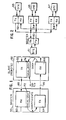
- FIG. 1 A simplified communication system according to the present invention, comprising a pair of modems, is shown in Fig. 1, wherein a master modem 50 communicates with a remote modem 52.
- the remote modem 52 operable as a slave modem with respect to a master modem 50, includes a transmitter 62 which communicates with the receiver 60 portion of the master modem 50.
- the master modem transmitter 64 communicates with the slave modem 52 receiver 66 providing a bidirectional transfer of data over a transmission line having paths 68 and 70.
- the paths 68 and 70 are provided by a bidirectional data channel incorporating quadrature modulation well known in the art and not discussed here.
- the remote transmitter Before the DTE data is transmitted, the remote transmitter, initially uncompensated or unequalized, transmits a sequence of training signals to the receiver 60 of the master modem 50.
- the receiver 60 self-synchronizes, and includes an equalizer 72 which self-adjusts over the period of training signals, typically a period of a fraction of a second, the -adjustment being described by equalizer coefficient and receiver timing values.
- the coefficient values 72 are transferred to the master modem 50 transmitter 64 and transmitted to the slave modem 52 receiver 66.
- the coefficients are then loaded into a transmitter equalizer 74, which is operable to pre-equalize the signal transmitted by the transmitter 62.
- the transmitter 62 of the slave modem 52 incorporates a pre-equalized transmission signal, eliminating the requirement that the master modem 50 receiver equalize the received signal to provide an error-free reception of data.
- the transmission from the slave modem 52 transmitter 62 is preceded by a short training sequence, wherein the receiver 60 finely readjusts its operating parameters, such as receiver data and carrier timing and phase. Thereafter, the exchange of DTE data commences.
- the master modem 50 communicates with a plurality of remote modems 52, 54, and 56, operable as slave modems with respect to the master modem 50.
- the present invention envisions a maximum of 99 such remote modems.
- the master modem 50, as well as each remote modem 52, 54, and 56, each have respective data terminal equipment (DTE) 51, 53, 55, and 57 associated therewith. All modems in the system according to the present invention are under strict control of the respective DTE. The initiation of communication and the. response thereto are directed by the respective DTE.
- DTE data terminal equipment
- the master DTE typically polls each of the DTEs by transmitting their respective address signal.
- the master modem 50 then converts the particular address signal into signals received by every remote modem 52, 54, and 56, wherein all associated DTE 53, 55, and 57 receive every address transmitted.
- the DTE Upon reception of its own address, the DTE responds with a request to send (RTS) to the respective modem, which in turn sends an acknowledge signal to the master modem, which is received by the controlling DTE.
- RTS request to send
- the coefficients provided by the master for each remote modem 52, 54, and 56 are received by the particular slave modem and stored in a particular memory location, shown as 74 in Fig. 1.
- the communicating modems need only exchange a short "fast" train signal sequence to provide the necessary mast --r modem receiver fine tuning. Thereafter, exchange of DTE data commences.
- Fig. 3 is a block diagram 50A of either the master modem 50 or one of the slave modems 52, 54, and 56 according to the present invention.
- the modem receives a signal at the input 82 of bandpass filter 84, which passes the frequencies of interest and rejects signals outside of the desired frequency band.
- the bandpass filter 84 output signal is received by an automatic gain control circuit 86 which normalizes the received signal to a more or less constant level, which is then digitized by analog-to-digital converter 88.
- the digitized signal is then received by a front end processor (FEP) 90, which includes apparatus to perform a Hilbert transform of particular received signals, discrete Fourier transforms, carrier detect circuit, and signal demodulation.
- FEP front end processor
- the FEP 90 provides a control signal to the AGC circuit 86 to maintain the signal at a desired amplitude level over varying conditions.
- a signal processor peripheral (SPP) 92 is connected to the FEP 90 and includes the adaptive equalizer, the phase recovery elements, the decision point generator, and other necessary functions, such as for receiver carrier recovery.
- the elements for the modem 50A receiver portion 60 described thus far are generally known in the art and not discussed herein.
- the FEP 90 and SPP 92 are incorporated by program control of an integrated circuit Part No. 7720, provided by NEC of Japan. The program control for implementation of the above-described functions are well within the skill of one in the communication and modem art and familiar with. the Part No. 7720, whose application and reference materials are herein incorporated.
- the resulting demodulated data signals produced by the FEP 90 are transmitted through the receiver control 80, and in particular a processor 94, and then to the DTE (not shown).
- the processor 94 arranges the signal bits in a particular serial signal format receivable by the associated DTE.
- the receiver control circuit 80 includes the processor 94 and associated RAM and PORT expansion circuit 96, Part No. 8155 of Intel Corporation, Sunnyvale, California, which communicates with the transmit control 100 of the modem 50A transmit circuit 70A.
- the receiver equalizer contained within the FEP 92, provides an equalizer function having a number of associated equalizer coefficients.
- the coefficients are received by the.-controller processor 94 of a master modem and transferred to the PORT expander circuit 96 for transfer to the transmit control 100 processor 102.
- the transfer of the equalizer coefficients in an eight-bit format, is provided over leads 110 for subsequent transfer.
- the coefficients comprise a sequence of path weights for a 15-tap T/2 equalizer.
- the received control circuit 80 and in particular the processor 94, sends signals to the transmit control processor 102, which directs the subsequent transfer and implementation of the coefficients according to vectored interrupts to direct subsequent processing of the data in the processor 102, the operation of interrupt service routines or programs being well known in the microprocessor art.
- the coefficients are stored for subsequent further use. The operation of stored coefficients is provided in more detail in patent application Serial No. 582,453, entitled “Modem Equalizer Training Using Previously Stored Parameters," incorporated herein by reference.
- the master receiver equalizer coefficients may be sent as data to a slave modem, once obtained within the master modem transmit circuit 100, as a phase of the long-train sequence described below.
- the master receiver equalizer coefficients are again transferred by vectored interrupts to the slave modem transmit circuit 100 for implementation in the transmit equalizer 120.
- the vector signals transmitted on lead 112 have a predetermined sequence of pulses from the transmitter port P3.1 (to the timer input) of the transmit control processor 102 concurrent with the transmission of coefficient values on leads 110.
- the timer input implemented within Intel 8039 processor circuit, increments a counter, whose value provides the interrupt vector for subsequent processor 102 transfer of the coefficients on leads 110.
- the operation and instruction manuals of the processor 94 and 102, as well as the port expander circuit 96 Part No. 8155, are incorporated by reference.
- the transmit control processor 102 Upon receipt of the vector signals, the transmit control processor 102 returns an acknowledge signal on lead 114 to the receive control processor 94.
- the transmit control processor 102 receives the data from the corresponding DTE (not shown) and transfers the data in modified form to a subsequent digital processor to provide the necessary transmit functions now described, and comprises Part No. 7720 of NEC, Japan.
- the data signal is received selectively through a data scrambler 104 according to operation of selector switch 106, wherein the scrambler 104 provides encoding according to a predetermined pseudorandom number sequence, well known in the art.
- the signal is received by a point generator 108 to provide a constellation of data points having corresponding unique phase and amplitude characteristics described by I and Q signal values.
- the particular point generated is determined to correspond to the value of the signals to be transmitted, including the training sequence and the plurality of data bits from the associated DTE.
- the I and Q signals produced by the point generator are selectively received by a shaping filter 122 according to operation of a switch 124 to include the equalizer 120, depending on the particular operational sequence step then in progress, discussed below with regard to Fig.
- Resulting signals from the shaping fil er 122 are received by a signal modulator 124 providing the particular quadrature modulation for transmission to the external equipment.
- a tone generator 126 is selectively provided according to operation switch 128 for inter- modem signalling, discussed below.
- the signals from either the modulator 124 or the tone generator 126 are then converted to analog form by a digital-to-analog converter 130 and then coupled to the transmission path on lead 132 by an amplifier 134 for proper signal level and isolation.
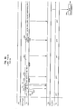
- FIG. 4A A typical long train sequence is sl.own in Figs. 4B and 4C.
- a preliminary long train sequence is shown in Fig. 4A, which occurs when the master modem is first turned on.
- the sequence of Fig. 4A commences with a 20-millisecond silient or off period 150 followed by a signal tone of 1700 Hz at period 152, corresponding to the selection of the tone generator 106 in Fig. 3.
- first and second tones T and T 2 are transmitted at 154 and 156, followed by a sequence of 128 baud of signals conforming to the CCITT specification V.29, Segment 2, at 158.
- a sequence of V.29, Segment 3 signals is transmitted to the receiving remote slave receiver(s) during period 160.
- a sequence of CCITT V.29, Segement 4 signals of 48 baud in duration is transmitted during the period 162.
- This sequence of signals of Fig. 4A, including intervals 150 through 162 is provided by the master modem to all remote slave modems then connected and turned on when the master modem is initially turned on.
- the user.data comprising polling addresses of the corresponding remote DTE is sent to all receiving modems, such as slave modems 52, 54, and 56 of Fig. 2.
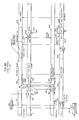
- a request to send signal is generated and causes the remote transmitter to begin a 25-baud duration of 1700 Hz tone at 170 in Fig. 4B, which when received by the master modem receiver at 172, disables circuits to the DTE, and the master modem responds by an initial off period of 20 milliseconds followed by a 1700 Hz signal at 174 and 176, respectively.
- the 1700 Hz signal is received by the remote slave modem at 178, wherein the remote receiver detects carrier and adjusts signal level by activation of the AGC circuit.
- the remote slave modem transmits tones T 1 and T 2 to the master modem at 173 and 175 to indicate the desired rate of signal transmission, and to indicate that a long train sequence is desired.
- the master modem provides a long train acknowledge tone T at interval 184, which is received by the remote modem receiver at 186. Thereafter, the master modem reduces signal transmission rate to a 7200-bps data rate, at 188. Subsequently, the master modem begins a V.29, Segment 2 sequence of 896-baud duration at 190, which is used to train the remote slave receiver modem equalizer at interval 192. Meanwhile, the remote slave modem has been transmitting alternations which comprise a sequence of alternating signals having a constant frequency and alternating phase, during interval 194, which is received by the master modem receiver at interval 196 to acquire frequency offset.
- the remote modem After an approximately 800-baud duration of alternations at 194, the remote modem provides a sequence of V.29, Segment 3 signals of approximately one-second duration at 198.
- the master modem receiver detects the transition between Segment 2 and Segment 3 at 200, and thereafter (at 201) converges the master modem receiver equalizer coefficients during the transmission of V.29, Segment 3 signals during interval 198.
- the remote modem transmitter thereafter begins the alternation signal sequence at 202.
- the master modem then transfers its receive equalizer coefficients to its transmitter circuit at 204, and begins to send the coefficients at 206 to the remote modem receiver at 208.
- the coefficients are transferred to the remote modem receiver circuit at 210 during the sequence of signal alterations at 202.
- the remote modem When the last coefficients are transmitted at 212 and accurately received at 214, the remote modem signals the master modem by a 20-m llisecond silent period, followed by a sequence of alternations of 211-baud duration, which is used by the master modem receiver to provide a coarse synchronization of receiver timing at 220.
- the remote modem receive circuit transfers the coefficients by vector interrupt to its transmit circuit for incorporation into its transmitter equalizer during the interval 230 beginning at period 234, producing pre-equalized alternations output from the remote transmitter.
- the master modem receiver measures a change in receiver timing c ⁇ r the timing shift (slew) at 234.
- the resulting timing measurement is transferred to the master modem transmitter at 236, and transmitted during interval 238 to the remote modem receiver at 240, which is in turn transferred to the remote modem transmit equalizer at time 242.
- the remote modem transmitter begins an off period at 244 of 20 milliseconds, followed by a fast train sequence at 246, discussed below.
- the user data is transmitted from the remote modem to the master modem during period 248.
- the master modem After the master modem transmits the slew data at interval 238, it begins a 20-millisecond quiet period at 250, followed by a 1700 Hz tone at 252, indicating that the training is complete. Thereafter, the master modem transmits a first and second tone at 254 and 256, to signal the remote modem of the rate at which data will be subsequently transmitted. Thereafter, during interval 258, 260, and 262, a sequence of intervals comprising the CCITT V.29, Segment 2, Segment 3, and Segment 4 signals are transmitted. Thereafter, at 264, the user data may be transmitted from the master to the remote modem.
- a 1700 Hz signal of 3.3-millisecond duration is transmitted to the master modem at interval 302, followed by a sequence of alernating signals of 25+1 baud duration.
- a synchronizing signal of predetermined nature is transmitted, followed by a signal indicating a subsequent data rate transmitted at periods 306 and 308, respectively.
- a mark signal is transmitted followed by the data from the remote to the master modem at 312.
Landscapes
- Engineering & Computer Science (AREA)
- Computer Networks & Wireless Communication (AREA)
- Signal Processing (AREA)
- Power Engineering (AREA)
- Communication Control (AREA)
- Cable Transmission Systems, Equalization Of Radio And Reduction Of Echo (AREA)
- Small-Scale Networks (AREA)
Applications Claiming Priority (2)
| Application Number | Priority Date | Filing Date | Title |
|---|---|---|---|
| US66786484A | 1984-11-02 | 1984-11-02 | |
| US667864 | 1984-11-02 |
Publications (2)
| Publication Number | Publication Date |
|---|---|
| EP0180066A2 true EP0180066A2 (fr) | 1986-05-07 |
| EP0180066A3 EP0180066A3 (fr) | 1987-12-23 |
Family
ID=24679978
Family Applications (1)
| Application Number | Title | Priority Date | Filing Date |
|---|---|---|---|
| EP85112691A Withdrawn EP0180066A3 (fr) | 1984-11-02 | 1985-10-07 | Système de communication à modem à branchements multiples |
Country Status (5)
| Country | Link |
|---|---|
| EP (1) | EP0180066A3 (fr) |
| JP (1) | JPS61181224A (fr) |
| CN (1) | CN85107938A (fr) |
| AU (1) | AU4847585A (fr) |
| NO (1) | NO853772L (fr) |
Cited By (20)
| Publication number | Priority date | Publication date | Assignee | Title |
|---|---|---|---|---|
| US4817114A (en) * | 1987-11-16 | 1989-03-28 | Ncr Corporation | Multipoint data modem communication system |
| US4847880A (en) * | 1988-01-13 | 1989-07-11 | Ncr Corporation | Multipoint modem system having fast synchronization |
| US4849996A (en) * | 1988-03-10 | 1989-07-18 | Ncr Corporation | Phase perturbation compensation system |
| US4849989A (en) * | 1988-01-13 | 1989-07-18 | Ncr Corporation | Data modem receiver |
| US4860308A (en) * | 1987-09-10 | 1989-08-22 | Ncr Corporation | Modem communication system having main and secondary channels |
| FR2639493A1 (fr) * | 1988-11-02 | 1990-05-25 | American Telephone & Telegraph | Procede et systeme pour obtenir le gain de codage theorique dans une transmission numerique avec correction d'erreur |
| EP0674420A1 (fr) * | 1994-03-23 | 1995-09-27 | AT&T Corp. | Appels de parole et de données commutés indépendamment utilisant un modem de parole et de données simultané |
| EP0711060A1 (fr) * | 1994-11-03 | 1996-05-08 | AT&T Corp. | Technique permettant d'établir rapidement des connexions PSTN à haute vitesse dans des applications télécommunication |
| EP0928088A3 (fr) * | 1997-12-05 | 2000-03-01 | Alcatel | Egalisation dans l'émetteur |
| WO2000016526A1 (fr) * | 1998-09-15 | 2000-03-23 | Koninklijke Philips Electronics N.V. | Systeme de transmission avec organe de conditionnement des signaux ameliore |
| EP0806852A3 (fr) * | 1996-05-09 | 2000-04-12 | Texas Instruments Incorporated | Modem multimode numérique |
| WO2001052490A1 (fr) * | 2000-01-14 | 2001-07-19 | Robert Bosch Gmbh | Procede et dispositif pour synchroniser des installations de transmission de donnees |
| EP1408662A1 (fr) * | 2002-10-11 | 2004-04-14 | Accelerant Networks, Inc. | Système et procédé pour égalisation de signaux à grande vitesse |
| US7593357B2 (en) | 2002-03-28 | 2009-09-22 | Interdigital Technology Corporation | Transmit processing using receiver functions |
| US7715471B2 (en) | 2003-12-17 | 2010-05-11 | Rambus, Inc. | Signaling system with selectively-inhibited adaptive equalization |
| US8994398B2 (en) | 2003-12-17 | 2015-03-31 | Rambus Inc. | High speed signaling system with adaptive transmit pre-emphasis |
| US9025678B2 (en) | 2003-04-09 | 2015-05-05 | Rambus Inc. | Partial response receiver |
| WO2016108467A1 (fr) * | 2014-12-30 | 2016-07-07 | 강수원 | Procédé d'égalisation à grande vitesse de données de paquet reçues en provenance d'un réseau à topologie de bus, procédé de transmission et de réception de données de paquet dans un réseau à topologie de bus et récepteur de réseau à topologie de bus |
| EP3190758A1 (fr) * | 2003-12-17 | 2017-07-12 | Rambus Inc. | Systeme de signalisation à vitesse elevée à preaccentuation, annulation de réflexion et annulation de décalage du niveau continu adaptives |
| US20230010016A1 (en) * | 2021-07-12 | 2023-01-12 | Realtek Semiconductor Corporation | Multidrop network system and network device |
Families Citing this family (2)
| Publication number | Priority date | Publication date | Assignee | Title |
|---|---|---|---|---|
| SE462704B (sv) * | 1987-12-09 | 1990-08-20 | Hg Tech Ab | Foerfarande vid atomisering av vaetskor och anordning foer genomfoerande av foerfarandet |
| DE19961594B4 (de) * | 1999-12-21 | 2013-08-14 | Ipcom Gmbh & Co. Kg | Verfahren für die Übertragung von Datensignalen zwischen einer Sendestation und mehreren Empfangsstationen, Sendestation und Empfangsstation |
Family Cites Families (3)
| Publication number | Priority date | Publication date | Assignee | Title |
|---|---|---|---|---|
| US4044307A (en) * | 1975-08-01 | 1977-08-23 | Milgo Electronic Corporation | Data modems with automatic equalization, drop-out detection and data echo protection |
| US4416015A (en) * | 1981-12-30 | 1983-11-15 | Bell Telephone Laboratories, Incorporated | Timing acquisition in voiceband data sets |
| US4489416A (en) * | 1983-03-18 | 1984-12-18 | Rixon, Inc. | Equalization system for modems in a polled arrangement |
-
1985
- 1985-09-25 NO NO853772A patent/NO853772L/no unknown
- 1985-10-07 EP EP85112691A patent/EP0180066A3/fr not_active Withdrawn
- 1985-10-10 AU AU48475/85A patent/AU4847585A/en not_active Abandoned
- 1985-10-28 CN CN198585107938A patent/CN85107938A/zh active Pending
- 1985-11-01 JP JP60246118A patent/JPS61181224A/ja active Pending
Cited By (47)
| Publication number | Priority date | Publication date | Assignee | Title |
|---|---|---|---|---|
| US4860308A (en) * | 1987-09-10 | 1989-08-22 | Ncr Corporation | Modem communication system having main and secondary channels |
| US4817114A (en) * | 1987-11-16 | 1989-03-28 | Ncr Corporation | Multipoint data modem communication system |
| US4847880A (en) * | 1988-01-13 | 1989-07-11 | Ncr Corporation | Multipoint modem system having fast synchronization |
| US4849989A (en) * | 1988-01-13 | 1989-07-18 | Ncr Corporation | Data modem receiver |
| US4849996A (en) * | 1988-03-10 | 1989-07-18 | Ncr Corporation | Phase perturbation compensation system |
| EP0332302A3 (en) * | 1988-03-10 | 1990-08-01 | Ncr Corporation | Phase perturbation compensation system |
| FR2639493A1 (fr) * | 1988-11-02 | 1990-05-25 | American Telephone & Telegraph | Procede et systeme pour obtenir le gain de codage theorique dans une transmission numerique avec correction d'erreur |
| US4995057A (en) * | 1988-11-02 | 1991-02-19 | At&T Bell Laboratories | Technique for achieving the theoretical coding gain of digital signals incorporating error correction |
| EP0674420A1 (fr) * | 1994-03-23 | 1995-09-27 | AT&T Corp. | Appels de parole et de données commutés indépendamment utilisant un modem de parole et de données simultané |
| EP0711060A1 (fr) * | 1994-11-03 | 1996-05-08 | AT&T Corp. | Technique permettant d'établir rapidement des connexions PSTN à haute vitesse dans des applications télécommunication |
| EP0806852A3 (fr) * | 1996-05-09 | 2000-04-12 | Texas Instruments Incorporated | Modem multimode numérique |
| EP0928088A3 (fr) * | 1997-12-05 | 2000-03-01 | Alcatel | Egalisation dans l'émetteur |
| WO2000016526A1 (fr) * | 1998-09-15 | 2000-03-23 | Koninklijke Philips Electronics N.V. | Systeme de transmission avec organe de conditionnement des signaux ameliore |
| US6714587B1 (en) | 1998-09-15 | 2004-03-30 | Koninklijke Philips Electronics N.V. | Transmission system with improved signal conditioning means |
| WO2001052490A1 (fr) * | 2000-01-14 | 2001-07-19 | Robert Bosch Gmbh | Procede et dispositif pour synchroniser des installations de transmission de donnees |
| US7349443B2 (en) | 2000-01-14 | 2008-03-25 | Ipcom Gmbh & Co. Kg | Method and device for synchronizing data transfer devices |
| US8531938B2 (en) | 2002-03-28 | 2013-09-10 | Interdigital Technology Corporation | Transmit processing using receiver functions |
| US7593357B2 (en) | 2002-03-28 | 2009-09-22 | Interdigital Technology Corporation | Transmit processing using receiver functions |
| EP1488543B1 (fr) * | 2002-03-28 | 2013-01-02 | Interdigital Technology Corporation | Procede de transmission faisant appel a des fonctions de reception |
| US7545860B2 (en) | 2002-10-11 | 2009-06-09 | Synopsys, Inc. | System and method of equalization of high speed signals |
| EP1408662A1 (fr) * | 2002-10-11 | 2004-04-14 | Accelerant Networks, Inc. | Système et procédé pour égalisation de signaux à grande vitesse |
| US7386053B2 (en) | 2002-10-11 | 2008-06-10 | Synopsys, Inc | System and method of equalization of high speed signals |
| US9407473B2 (en) | 2003-04-09 | 2016-08-02 | Rambus Inc. | Partial response receiver |
| US11502878B2 (en) | 2003-04-09 | 2022-11-15 | Rambus Inc. | Partial response receiver |
| US10764094B2 (en) | 2003-04-09 | 2020-09-01 | Rambus Inc. | Partial response receiver |
| US10225111B2 (en) | 2003-04-09 | 2019-03-05 | Rambus Inc. | Partial response receiver |
| US9025678B2 (en) | 2003-04-09 | 2015-05-05 | Rambus Inc. | Partial response receiver |
| US9917708B2 (en) | 2003-04-09 | 2018-03-13 | Rambus Inc. | Partial response receiver |
| US9705710B2 (en) | 2003-12-17 | 2017-07-11 | Rambus Inc. | High speed signaling system with adaptive transmit pre-emphasis |
| US10411923B2 (en) | 2003-12-17 | 2019-09-10 | Rambus Inc. | High speed signaling system with adaptive transmit pre-emphasis |
| US11706061B2 (en) | 2003-12-17 | 2023-07-18 | Rambus Inc. | High speed signaling system with adaptive transmit pre-emphasis |
| US7715471B2 (en) | 2003-12-17 | 2010-05-11 | Rambus, Inc. | Signaling system with selectively-inhibited adaptive equalization |
| EP3190758A1 (fr) * | 2003-12-17 | 2017-07-12 | Rambus Inc. | Systeme de signalisation à vitesse elevée à preaccentuation, annulation de réflexion et annulation de décalage du niveau continu adaptives |
| US11233678B2 (en) | 2003-12-17 | 2022-01-25 | Rambus Inc. | High speed signaling system with adaptive transmit pre-emphasis |
| US9287909B2 (en) | 2003-12-17 | 2016-03-15 | Rambus Inc. | High speed signaling system with adaptive transmit pre-emphasis |
| US10771295B2 (en) | 2003-12-17 | 2020-09-08 | Rambus Inc. | High speed signaling system with adaptive transmit pre-emphasis |
| US9000803B2 (en) | 2003-12-17 | 2015-04-07 | Rambus Inc. | High speed signaling system with adaptive transmit pre-emphasis |
| US8994398B2 (en) | 2003-12-17 | 2015-03-31 | Rambus Inc. | High speed signaling system with adaptive transmit pre-emphasis |
| US10270617B2 (en) | 2014-12-30 | 2019-04-23 | Vsi Corporation | Method and apparatus for high speed equalization of data packet received from bus topology network |
| KR101642611B1 (ko) * | 2014-12-30 | 2016-07-29 | 강수원 | 버스 기반 네트워크에서 수신한 패킷 데이터를 고속 등화하는 방법, 버스 기반 네트워크에서 패킷 데이터를 송수신하는 방법 및 버스 기반 네트워크의 수신기 |
| EP3242451A4 (fr) * | 2014-12-30 | 2018-09-05 | Suwon Kang | Procédé d'égalisation à grande vitesse de données de paquet reçues en provenance d'un réseau à topologie de bus, procédé de transmission et de réception de données de paquet dans un réseau à topologie de bus et récepteur de réseau à topologie de bus |
| CN107135670B (zh) * | 2014-12-30 | 2020-10-16 | Vsi 株式会社 | 总线拓扑网络中的报文数据高速均衡化的方法、报文数据发送和接收方法、及接收机 |
| CN107135670A (zh) * | 2014-12-30 | 2017-09-05 | 姜守元 | 对接收自总线拓扑网络的报文数据的高速均衡化的方法、总线拓扑网络中发送和接收报文数据的方法及总线拓扑网络的接收机 |
| WO2016108467A1 (fr) * | 2014-12-30 | 2016-07-07 | 강수원 | Procédé d'égalisation à grande vitesse de données de paquet reçues en provenance d'un réseau à topologie de bus, procédé de transmission et de réception de données de paquet dans un réseau à topologie de bus et récepteur de réseau à topologie de bus |
| KR20160082341A (ko) * | 2014-12-30 | 2016-07-08 | 강수원 | 버스 기반 네트워크에서 수신한 패킷 데이터를 고속 등화하는 방법, 버스 기반 네트워크에서 패킷 데이터를 송수신하는 방법 및 버스 기반 네트워크의 수신기 |
| US20230010016A1 (en) * | 2021-07-12 | 2023-01-12 | Realtek Semiconductor Corporation | Multidrop network system and network device |
| US11750434B2 (en) * | 2021-07-12 | 2023-09-05 | Realtek Semiconductor Corporation | Multidrop network system and network device |
Also Published As
| Publication number | Publication date |
|---|---|
| JPS61181224A (ja) | 1986-08-13 |
| NO853772L (no) | 1986-05-05 |
| CN85107938A (zh) | 1986-09-10 |
| EP0180066A3 (fr) | 1987-12-23 |
| AU4847585A (en) | 1986-05-08 |
Similar Documents
| Publication | Publication Date | Title |
|---|---|---|
| EP0180066A2 (fr) | Système de communication à modem à branchements multiples | |
| US4621366A (en) | Modem equalizer training using previously stored parameters | |
| US5852630A (en) | Method and apparatus for a RADSL transceiver warm start activation procedure with precoding | |
| JP3310664B2 (ja) | データ通信システムの等化方法及び等化システム | |
| US4995057A (en) | Technique for achieving the theoretical coding gain of digital signals incorporating error correction | |
| US4792940A (en) | Automatic retrain method for a full duplex modem having an echo canceller and an equalizer | |
| US5052024A (en) | Offset frequency multipoint modem and communications network | |
| JPH02256361A (ja) | 改良形半二重化モデム通信方式およびその通信方法 | |
| EP0441055A2 (fr) | Procédé et appareil pour la réduction du temps d'inversion sur la voie dans une transmission de fac-similé | |
| US5115451A (en) | Local area network modem | |
| JPH0758982B2 (ja) | 非同期デ−タのブロックモード伝送方法及びデ−タユニツト | |
| US4044307A (en) | Data modems with automatic equalization, drop-out detection and data echo protection | |
| CA1291545C (fr) | Recepteur de modem | |
| EP0112395B1 (fr) | Systeme d'apprentissage pour recepteur de donnees | |
| US4669090A (en) | Half-duplex modem without turnaround delay | |
| US4009356A (en) | Data modems having data drop-out and data echo protection | |
| WO1996013908A1 (fr) | Procede permettant d'etablir une connexion de signal mia utilisant une sequence d'apprentissage | |
| EP0169548A2 (fr) | Procédé et dispositif d'identification automatique d'un modem répondant dans un circuit à plusieurs stations | |
| US5541967A (en) | Fast symbol synchronization for use in conditioning a receiving modem | |
| US4637064A (en) | Local area network equalization system and method | |
| CA1240750A (fr) | Reseau de communication a unites de connexion a fonction d'ajustement de gain pour amplificateur de transmission | |
| EP1393541B1 (fr) | Initialisation a état de longueur de longeur variable pour systems DSL | |
| EP1214820A1 (fr) | Modem pcm avec precodage et pre-egalisation | |
| AU2002305831A1 (en) | Variable state length initialization | |
| US5422606A (en) | Automatic equalizer |
Legal Events
| Date | Code | Title | Description |
|---|---|---|---|
| PUAI | Public reference made under article 153(3) epc to a published international application that has entered the european phase |
Free format text: ORIGINAL CODE: 0009012 |
|
| AK | Designated contracting states |
Kind code of ref document: A2 Designated state(s): BE DE FR GB IT LU NL SE |
|
| PUAL | Search report despatched |
Free format text: ORIGINAL CODE: 0009013 |
|
| AK | Designated contracting states |
Kind code of ref document: A3 Designated state(s): BE DE FR GB IT LU NL SE |
|
| STAA | Information on the status of an ep patent application or granted ep patent |
Free format text: STATUS: THE APPLICATION IS DEEMED TO BE WITHDRAWN |
|
| 18D | Application deemed to be withdrawn |
Effective date: 19871103 |
|
| RIN1 | Information on inventor provided before grant (corrected) |
Inventor name: BURCH, RICHARD A. Inventor name: MCMAHAN, DENNIS B. |
|
| P01 | Opt-out of the competence of the unified patent court (upc) registered |
Effective date: 20230525 |