EP0180095A2 - Radschlupfregelsystem für ein Fahrzeug - Google Patents
Radschlupfregelsystem für ein Fahrzeug Download PDFInfo
- Publication number
- EP0180095A2 EP0180095A2 EP85113147A EP85113147A EP0180095A2 EP 0180095 A2 EP0180095 A2 EP 0180095A2 EP 85113147 A EP85113147 A EP 85113147A EP 85113147 A EP85113147 A EP 85113147A EP 0180095 A2 EP0180095 A2 EP 0180095A2
- Authority
- EP
- European Patent Office
- Prior art keywords
- valve
- slip
- controlling
- pressure
- driven wheels
- Prior art date
- Legal status (The legal status is an assumption and is not a legal conclusion. Google has not performed a legal analysis and makes no representation as to the accuracy of the status listed.)
- Granted
Links
- 230000001133 acceleration Effects 0.000 claims abstract description 39
- 230000001276 controlling effect Effects 0.000 claims description 71
- 230000004044 response Effects 0.000 claims description 4
- 230000001105 regulatory effect Effects 0.000 claims description 2
- 230000001934 delay Effects 0.000 claims 1
- 230000004069 differentiation Effects 0.000 claims 1
- 230000004043 responsiveness Effects 0.000 abstract 1
- 238000002485 combustion reaction Methods 0.000 description 14
- 239000003921 oil Substances 0.000 description 10
- 239000000446 fuel Substances 0.000 description 7
- 238000010276 construction Methods 0.000 description 6
- 230000007246 mechanism Effects 0.000 description 6
- 238000001514 detection method Methods 0.000 description 5
- 238000010586 diagram Methods 0.000 description 5
- 230000000694 effects Effects 0.000 description 4
- 238000000034 method Methods 0.000 description 4
- 230000008569 process Effects 0.000 description 4
- 230000008859 change Effects 0.000 description 3
- 238000002347 injection Methods 0.000 description 3
- 239000007924 injection Substances 0.000 description 3
- 230000005540 biological transmission Effects 0.000 description 2
- 230000003247 decreasing effect Effects 0.000 description 2
- 208000036366 Sensation of pressure Diseases 0.000 description 1
- 230000002159 abnormal effect Effects 0.000 description 1
- 239000010720 hydraulic oil Substances 0.000 description 1
- 230000002265 prevention Effects 0.000 description 1
- 230000003449 preventive effect Effects 0.000 description 1
- 230000009467 reduction Effects 0.000 description 1
Images




Classifications
-
- B—PERFORMING OPERATIONS; TRANSPORTING
- B60—VEHICLES IN GENERAL
- B60T—VEHICLE BRAKE CONTROL SYSTEMS OR PARTS THEREOF; BRAKE CONTROL SYSTEMS OR PARTS THEREOF, IN GENERAL; ARRANGEMENT OF BRAKING ELEMENTS ON VEHICLES IN GENERAL; PORTABLE DEVICES FOR PREVENTING UNWANTED MOVEMENT OF VEHICLES; VEHICLE MODIFICATIONS TO FACILITATE COOLING OF BRAKES
- B60T8/00—Arrangements for adjusting wheel-braking force to meet varying vehicular or ground-surface conditions, e.g. limiting or varying distribution of braking force
- B60T8/32—Arrangements for adjusting wheel-braking force to meet varying vehicular or ground-surface conditions, e.g. limiting or varying distribution of braking force responsive to a speed condition, e.g. acceleration or deceleration
- B60T8/34—Arrangements for adjusting wheel-braking force to meet varying vehicular or ground-surface conditions, e.g. limiting or varying distribution of braking force responsive to a speed condition, e.g. acceleration or deceleration having a fluid pressure regulator responsive to a speed condition
- B60T8/48—Arrangements for adjusting wheel-braking force to meet varying vehicular or ground-surface conditions, e.g. limiting or varying distribution of braking force responsive to a speed condition, e.g. acceleration or deceleration having a fluid pressure regulator responsive to a speed condition connecting the brake actuator to an alternative or additional source of fluid pressure, e.g. traction control systems
-
- B—PERFORMING OPERATIONS; TRANSPORTING
- B60—VEHICLES IN GENERAL
- B60T—VEHICLE BRAKE CONTROL SYSTEMS OR PARTS THEREOF; BRAKE CONTROL SYSTEMS OR PARTS THEREOF, IN GENERAL; ARRANGEMENT OF BRAKING ELEMENTS ON VEHICLES IN GENERAL; PORTABLE DEVICES FOR PREVENTING UNWANTED MOVEMENT OF VEHICLES; VEHICLE MODIFICATIONS TO FACILITATE COOLING OF BRAKES
- B60T8/00—Arrangements for adjusting wheel-braking force to meet varying vehicular or ground-surface conditions, e.g. limiting or varying distribution of braking force
- B60T8/17—Using electrical or electronic regulation means to control braking
- B60T8/175—Brake regulation specially adapted to prevent excessive wheel spin during vehicle acceleration, e.g. for traction control
Definitions
- This invention relates to a wheel slip controlling system for controlling a frictional force between a tire of a driven wheel and the road surface not only during braking but also during acceleration of a car, and more particularly a wheel slip controlling system to control rotation of a driven wheel by brake mechanism as well as to control an output power of an internal combustion engine.
- An traction controlling system which controls rotation of a wheel during acceleration of a car to provide a maximum frictional force between a tire of a wheel and the road surface so as to improve the stability and acceleration.
- this kind of traction controlling system normally, considered is such a system as detecting the state of slipping of a driven wheel and controlling the power of internal combustion engine by controlling the elements like ignition timing or fuel injection amount so as to control the rotation of a driven wheel when the degree of slipping is above a predetermined value.
- the conventional wheel slip controlling systems aim at the prevention of slip during acceleration by reducing the fuel injection amount or setting a time lag against a change in the ignition timing so as to control the output of the internal combustion engine.
- the control capacity being limited, taking preventive measures against abnormal vibration, or stop due to abrupt changes in the operating conditions of engine.
- the objective of the present invention is to solve the above-mentioned problems once for all and offer a wheel slip controlling system capable of carrying out the fine control without any decrease in drivability and safety of vehicles as well as any delay in control when the slip of driven wheels occurs during acceleration operation.
- the second objective of the present invention is to offer a wheel slip controlling system wherein the slip of driven wheels during acceleration operation can be controlled by brake system with quick response and the second throttle valve which controls the intake air amount in longer period.
- It is the third objective of the present invention is to offer a wheel slip controlling system wherein the braking force necessary for the brake mechanism is reduced by employing the two means for controlling the rotation of driven wheels together so as to be capable of not only reducing the system in size and weight but achieving the saving of fuel consumption.
- the fourth objective of the present invention is to offer a wheel slip controlling system whose constitution is superior in various points, e.g., capability of conducting the fine control of braking force with simplified structure by utilizing the anti-skid control system for brake mechanism, etc-.
- the fifth objective of the present invention is to offer a wheel slip controlling system wherein security will be kept by adjusting the intake air amount with the first throttle valve operated during a driver's acceleration operation even if the throttle valve drive device is out of order, as the output power of internal combustion engine is reduced by the second throttle valve.
- inventive wheel slip controlling system features comprise as shown in Fig. 1.
- a wheel slip controlling system comprising:
- the slip detecting means M3 detects the degree of slipping in relation to road surfaces when a driven wheel M1 is in the state of acceleration. Therefore, accepted is such means as detecting the difference of rotation states between a non-driven wheel and a driven wheel M1, or comparing the actual rotation speed of a driven wheel M3 with the theoretical value of rotation state of the driven wheel M1 without excessive slipping.
- the rotation controlling means controls the rotation of the driven wheel M1.
- There are two control means namely, the second throttle valve M7 operated by a driver, which is provided to the intake air path so as to control the intake air amount like the first throttle valve M6 and the brake mechanism provided with anti-skid controlling means M4 which changes the braking force supplied to the driven wheel M1 properly when slip occurs during deceleration operation.
- the output power of internal combustion engine which operates the driven wheel M1 is decreased by the second throttle valve M7 so as to control the rotation of the driven wheel M1.
- the control is carried out by giving the braking force against the rotation of the driven wheel M1 with anti-skid controlling means M4.
- Traction controlling means M8 operates the rotation controlling means when it judges the state of slipping as beyond the capacity of the driven wheel M1 during acceleration operation on the basis of the detected results by the slip detecting means M3. So when the traction controlling means M8 decides that the excessive rotation force is given to the driven wheel M1, it operates the second throttle valve M7 to decrease the driving force of the driven wheel M1, in addition, the braking mechanism of anti-skid controlling means M4 is activated to give the braking force to the driven wheel M1.
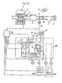
- Fig. 2 is a schematic diagram of a braking hydraulic system and a controlling system therefor in a car on which a wheel slip controlling system of a first embodiment of the present invention is installed.
- numeral 1 denotes an engine
- numeral 2 denotes a piston
- 3 for a spark plug 4 for a suction valve
- 5 for a fuel injector 6 for a surge tank
- 7 for an air-flow meter 8 for an air cleaner.
- a first throttle valve 10 which is prepared conventionally and ajusts the intake air amount interlocked to an accelerator pedal 9
- a second throttle valve 14 which adjusts the intake air amount like the first throttle valve 10 and is driven by a DC motor 12 is provided to an intake air path between the air-flow meter 7 and the surge tank 6.
- the second throttle valve 7 is in the state of full open under the normal condition.
- the position of the valve 7 is controlled from the full open to the full close so as to control the output power of internal combustion engine and carry out the slip control only when the traction control is executed.
- reference numeral 20 denotes a hydraulic system of a conventional anti-skid brake system and 30 a hydraulic system newly provided afresh for traction control.
- a foot brake 50 is treaded to operate a master cylinder 51 of the tandem type, a braking force is produced at both of left and right front wheels (FL, FR) and left and right rear wheels (RL, RR) corresponding to a hydraulic pressure, and the hydraulic system 20 of an anti-skid brake system for suitably varying the hydraulic pressure of the hydraulic circuit is provided in the hydraulic circuit.
- Fig. 2 shows only a hydraulic oil path for the rear wheels in detail for simplification.
- Rotational speeds of the front and rear wheels to which a braking force is applied in such a manner as described above are detected by a car speed sensor 60A and a wheel speed sensor 60B and are transmitted to an electronic controlling device 90.
- the car speed sensor 8A calculates an average of rotational speeds of the left and right front wheels FL and FR and thus outputs a signal which is regarded as a travelling speed of the car while the wheel speed sensor 60B outputs a signal indicative of a rotational speed of a driven wheel only.
- the hydraulic system 20 of the anti-skid brake system includes a cut valve 24 to which a flow of oil is changed over by means of a three position solenoid valve 23 from a hydraulic source of an accumulator 22 which stores therein oil to be fed under pressure by a hydraulic pump 21, a bypass valve 25 for assuring operation of the braking hydraulic circuit when the hydraulic source gets out of order and so on, a reservoir 26 for temporarily storing excessive oil therein, and a hydraulic switch 27 for detecting a hydraulic pressure of the hydraulic source to provide an output when a predetermined hydraulic pressure is obtained.
- Fig. 2 indicates the hydraulic system when the anti-skid brake system does not operate.
- a piston of the bypass valve 25 is normally held upward by oil pressure from the accumulator 22 which is maintained at a high pressure by the pump 21 so that oil from a pressure change-over valve 31 which will be hereinafter described does not go into the bypass valve 25 and all flows into the cut valve 24.
- a piston of the cut valve 24 is also held upward since the three position valve 23 is connected at an A port thereof to the cut valve 24.
- the upward pressure of the accumulator 22 is higher than the pressure of the pressure change-over valve 31, and accordingly oil which flows into the cut valve 24 from the pressure change-over valve 31 goes out of an upper chamber of the cut valve 24, passing a bypass path 28 and then an upper chamber of the bypass valve 25, and provides a braking force to the driven wheels RR and RL.
- bypass valve 25 only acts as a bypass hydraulic path which imparts a braking force to driven wheels via an upper chamber of the bypass valve 15 so far as the hydraulic pressure from the accumulator 22 is normal while the cut valve 24 holds the capacity of the upper chamber thereof to its minimum and unchangeable when the three position valve 23 is connected at the A port thereof to the cut valve 24 so that the braking hydraulic pressure can be controlled only by a pressure of the pressure change-over valve 31.
- the electronic controlling device 90 actuates the three position valve 23 to connect a C port of the latter to the hydraulic system. Then, the pressure in a lower chamber below the piston of the cut valve 24 becomes equal to the low pressure of the reservoir 26, and as a result, the piston is pushed down by the pressure of the pressure change-over valve 31 to increase the volume of oil and lower the hydraulic pressure in the upper chamber of the cut valve 24 which has provided the braking force to the driven wheels RR and RL, resulting in reduction in the braking force.
- the pressure change-over valve 31 is a valve of the 2-input 1- output type which selectively outputs one of two inputs which is higher in pressure than the other.
- the master cylinder 51 of the foot brake 50 is connected to one of the two inputs of the pressure change-over valve 31 while another cylinder 32 is connected to the other input.
- the above described accumulator 22 serves as a power source for operating the cylinder 32, and a two position valve 33 which is controlled by the electronic controlling device 90 intermits connection between the accumulator 22 and the cylinder 32.
- the electronic controlling device 90 detects a condition of the braking hydraulic system as described above and produces a controlling output depending upon such detection.
- the electronic controlling device 90 receives three output signals from the car speed sensor 60A, the wheel speed sensor 60B and the hydraulic switch 27 as detection information of the braking hydraulic system and controls the pump 21, the three position valve 23 and the two position valve 33 within the hydraulic system and the DC motor 12 in accordance with results of such detection.
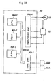
- Fig. 2 illustrates a block diagram wherein the electronic controlling device 90 is constructed as an example from digital circuits including a microcomputer at the center thereof. Referring to Fig.
- reference symbol 90A-1 denotes a CPU which carries out operation
- 90A-2 a ROM which stores a controlling program and various constants therein
- 90A-4 an input/output port which outputs controlling signals for operating the DC motor 12, several hydraulic valves and the pump 21 in the hydraulic system and which shapes and receives a signal from the hydraulic switch 27,
- 90A-5 an input port which receives signals from the two speed sensors, and
- 90A-6 a bus line forming a passage of information.
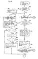
- the wheel slip controlling system of the present embodiment having such a construction as described above operates in accordance with a flow chart illustrated in Fig. 3.
- the flow chart indicates a wheel slip controlling routine which is stored in prior in the ROM 90A-2 and is executed repeatedly every predetermined period of time to control a slip of wheels.
- step 100 is executed to discriminate if the pressure of the hydraulic system is normal or not.
- the pressure of the accumulator 22 of the anti-skid brake system is detected by the hydraulic switch 27 as described hereinabove, and if the pressure lowers, the hydraulic switch 27 will provide no output.
- step 110 is once executed to operate the pump 21 to raise the pressure of the accumulator 22 until there appears an output of the hydraulic switch 27 again.
- step 120 if there is an output of the hydraulic switch 27 and thus the pressure is discriminated as normal, there is no necessity of executing the process of step 110 and control advances directly to next step 120.
- a step 120 it is discriminated if the car is now being accelerated or decelerated.
- acceleration is calculated from a frequency of pulse signals from the car speed sensor 60A and it is discriminated if a result of the calculation is equal to or over zero.
- control advances to step 130 to execute a following traction control.
- step 140 is executed to reset a counter C which is used in the traction control as hereinafter described whereafter the present routine is finished and another routine for a conventional anti-skid control not shown will be executed.
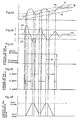
- the upper limit value means a speed represented by a line Vh illustrated in (A) of Fig. 4 and is a rotational speed at which a maximum frictional force acts on the driven wheels as calculated from the detection result Vc of the car speed sensor 60A, that is, an upper limit value within a range of rotational speed of the driven wheels at which the slip ratio becomes - 10% or so.
- Reference symbol V2 in (A) of Fig. 4 indicates a lower limit value of the range.
- step 150 is executed to set the counter C to a predetermined positive integer to drive the second throttle valve 14 toward close side by the DC motor 12 and then at the following step 160, a changing over operation is executed to change over the two position valve 33 to a pressurizing side wherein the pressure of the accumulator 22 is imparted to the pressure change-over valve 31.
- the output power of the internal combustion engine 1 which drives the driven wheels RL and RR is kept low and a braking pressure is applied to the cut valve 24 so that a braking force acts upon the driven wheels RR and RL.
- step 170 is executed to discriminate if the rotational speed Vr and the acceleration ⁇ r of the driven wheel RL exceed their respective upper limit values.
- the upper and lower limit values of the acceleration mean predetermined values ⁇ h and ⁇ l as respectively, illustrated in (B) of Fig. 4, and represent upper and lower limit values of the acceleration which can assume while a large frictional force is maintained between the driven wheels and the road surface as estimated from the weight of the car, a load to the driven wheels, and so on.
- step 180 is executed to carry out a changing over control to the A port of the three position valve wherein pressurization from the pressure change-over valve 31 to the cut valve 24 all acts as a braking force.
- step 170 it is not discriminated that the condition is met, it is discriminated at 190 if the actual rotational speed Vr and acceleration ⁇ r of the driven wheels are higher or not than the lower limit values Vl and ⁇ l for the speed and acceleration, respectively.
- Vr and ⁇ r the actual rotational speed
- Vl and ⁇ l the lower limit values
- the magnitude of a braking force to the driven wheels is regarded as suitable at present and the three position valve 23 is changed over to the B port to maintain constant volume of the upper chamber which imparts the braking force of the cut valve 24 (step 200).
- step 190 if it is discriminated at step 190 that either one or both of the speed and the acceleration are below the lower limit value or values thereof, it is regarded that a braking force greater than a required level is applied to the driven wheels so that the C port of the three position valve 23 is connected to the hydraulic system to increase the volume of the upper chamber of the cut valve 24 and to reduce the braking force to the driven wheels (step 210).
- steps 220 to 270 which are executed when it is discriminated at step 130 that the condition is not met are provided to set a delay time to control of the two position valve 33 toward discommunicating side and the second throttle valve toward close side.
- the position of the second throttle valve is operated toward close side so as to be capable of keeping the output power of the internal combustion engine 1 low and-the two position valve 33 is drived which is normally at a pressure discommunicating side wherein the pressure of the accumulator 22 is not imparted to the pressure change-over valve 31, and thus the brake is rendered effective by the pressure of the accumulator 22.
- the three position valve 23 is suitably actuated to accomplish traction control to obtain an optimum driving force in order to effect fine control of the braking force corresponding to variations of the rotational speed Vr and the acceleration ⁇ r of the driven wheels.
- step 130 If a negative decision is made at step 130 with the traction control mentioned above continued, the position of the second throttle valve 14 is operated toward close side at steps 220 and 230. Namely, whether the rotational speed Vr has already been below the lower limit value Vl or not is tested (at step 220), if Vr ⁇ VQ , the DC motor 12 is operated in opposite rotation to that at step 150 mentioned above so as to operate the position of the second throttle valve 14 toward open side at step 230 because carried out is such a judgment as being unnecessary to lower the output power of the internal combustion engine 1 down to the existing level. If Vr k Vl, it is not necessary to change the position of the throttle valve 14, thus the steps followed by step 240 will be carried out without the execution of step 230.
- switching of the two position valve 33 to the pressure discommunicating side is executed after the predetermined period of time.
- the above-mentioned routine is executed again after lapse of the predetermined period of time, if at step 130 it is discriminated that the rotational speed Vr of the driven wheels is not over the upper limit value Vh therefor and the two position valve 33 is promptly changed over to the pressure discommunicating side, then the braking force which has acted upon-the driven wheels so far will disappear completely and thus vibrations due to such control may be brought about to the car.
- step 130 the control of the second throttle valve 14 has been completed, at first step 240 is executed to determine if the contents of the counter C which was set at step 150 are greater than zero or not, and if C > 0, then the counter C is decremented at step 250, and then if it is discriminated at step 260 that the new contents of the counter C are not zero, then the aforementioned steps including step 160 are executed again.
- step 270 it is regarded that the two position valve 33 is held to the pressure communicating side for the predetermined period of time so that control now proceeds to step 270 at which the two position valve 33 is changed over to the pres-sure discommunicating side to effect control of the next steps including 180 is executed without decrementing the counter C again in accordance with the discrimination at step 240.
- Controls of the two position valve 33 and the three position valve 13 which are executed in the control of the present step are illustrated in (C), (D) and (E) of Fig. 4.
- (C), (D) and (E) of Fig. 4 once the two position valve 33 is rendered operative, it effects transmission of pressure to produce a braking force until the car is brought to a stabilized accelerated condition due to a delay time Td of the two position valve 33, that is, the time preset by the counter while the three position valve 23 suitably changes over the three ports thereof to adjust the braking force to execute the traction control.
- the output power of the internal combustion engine 1 is decreased in accordance with the decrease of the intake air amount when the rotational speed of driven wheels becomes too high by controlling the position of the second throttle valve 14. On the contrary, it is increased in accordance with the increase of the intake air amount when the rotational speed becomes too low because of the braking force of aforementioned brake mechanism.
- the car speed sensor 60A and the wheel speed sensor 60B correspond to the slip detecting means I and what compares the output power of these sensors with the upper and lower limits of rotational speed and acceleration of driven wheels, then controls the rotation control means III, i.e., the second throttle valve 14 and the hydraulic system of an anti-skid brake system, based on the compared results corresponds to the rotating force control means.
- the rotation control means III i.e., the second throttle valve 14 and the hydraulic system of an anti-skid brake system
- the present embodiment thus indicates an excellent example of constitution of a wheel slip controlling system which can attain traction control during acceleration of a car as shown in (A) of Fig. 4 only by additionally providing a hydraulic controlling system 30 and the second throttle valve 14 for traction control as described above.
- the traction control with the good efficiency can be achieved, employing the braking system in accordance with the hydraulic pressure for quick response and the second throttle valve 14 for controlling the rotation in comparatively longer period, respectively.
- control of the braking force is all accomplished by the common three position valve 23 of the anti-skid brake system in order to simply attain such excellent effects as described above
- the two position valve 33 may otherwise be replaced by a three position valve which is controlled to regulate the tracking hydraulic pressure itself which is provided to the pressure change-over valve 31.
- Control of the three position valve in the latter case may be one which execute substantially the same routine as that of Fig.
- the pressure of the accumulator 22 may be imparted to the pressure change-over valve 31, but when they are both lower than the respective lower limit values therefor, the pressure of the accumulator 22 may be reduced and when in any conditions, the braking force may be maintained constant.
- the electronic controlling device 90 is constructed from electronic circuits without using a microcomputer.
- the second embodiment has, in hardware, a circuitry construction as illustrated in Fig. 5.
- reference symbols 90B-1 and 90B-2 denote F/V converters for converting a frequency of pulse signals developed from left and right idle wheel speed sensors 60A-1 and 60A-2 and corresponding to rotations of. idle wheels into a voltage signal
- reference symbol 90B-3 designates an adder for adding the thus converted voltage signal to obtain a voltage Bf corresponding to the travelling speed of the car (hereinafter referred to as a car speed voltage)
- 90B-4 a differentiator for differentiating the car speed voltage Bf to obtain a voltage Bf corresponding to an acceleration of the car
- 90B-5 a comparator for comparing the car acceleration voltage Bf with the ground voltage (0 volt) to determine if the car is being accelerated or not.
- reference symbol 90B-6 denotes an F/V converter for converting a frequency of pulse signals developed from the wheel speed sensor 60B into a voltage signal
- 90B-7 an amplifier for amplifying the voltage signal from the F/V converter 90B-6 to a voltage corresponding to the car speed voltage Bf obtained from the adder 90B-3 to obtain a driven wheel speed voltage Br indicative of the speed Vr of driven wheels
- 90B-8 a differentiator for differentiating the driven wheel speed voltage Br to output a driven wheel acceleration voltage Br.
- reference symbols 90B-9 and 90B-10 denote adders for adding predetermined voltages B1 and B2 to the car speed voltage Bf developed from the adder 90B-3 and corresponding to the travelling speed of the car to output reference voltages Bf1 and Bf2 for determination of a degree of an acceleration slip of the car, respectively, 90B-11 and 90B-12 comparators for comparing the reference voltages Bf1 and Bf2 outputted from the adders 90B-9 and 90B-10 with the driven wheel speed voltage Br outputted form the amplifier 90B-7 to output voltage signals Bf and Bfh of a high level when Bf1 á Br and Bf2 i Br, respectively, and 90B-13 and 90B-14 further comparators for comparing the driven wheel acceleration voltage Br outputted from the differentiator 90B-8 with predetermined voltages B3 and B4 to output voltage signals Br and Brh of a high level when Br z B3 and Br k B4, respectively.
- the voltage signals Bfl and Brl outputted from the comparators 90B-11 and 90B-13 are inputted to an AND circuit 90B-15.
- a voltage signal Bl outputted from the AND circuit 90B-15 is inputted to another AND circuit 90B-30 at the next stage, and a signal Bl' outputted from the AND circuit 90B-30 is provided via an amplifier 90B-16 to the base of a transistor Tr1 as a controlling signal for changing over the three position valve 23 to the A port or to the C port.
- the voltage signals Bfh and Brh outputted from the comparators 90B-12 and 90B-14, respectively, are inputted to a further AND circuit 90B-17, and a signal from the hydraulic switch 27 is also inputted to the AND circuit 90B-17 via a NOT circuit 90B-18.
- a voltage signal Bh outputted form the AND circuit 90B-17 is inputted to a yet further AND circuit 90B-31 from which a voltage signal Bh' is outputted.
- the voltage signal Bh' is applied via an amplifier 90B-19 to the base of another transistor Tr2 as a controlling signal for changing over the three position valve 23 to the B port.
- an output of an AND circuit 90B-21 is inputted via the AND circuits 90B-30 and 90B-31 to the amplifiers 90B-19 and 90B-16, respectively. Accordingly, the three position valve 23 is normally controlled to the A port.
- a voltage signal which is outputted from the comparator 90B-5 and indicates that the car is in accelerating condition, another voltage signal outputted from the comparator 90B-12 via a delay circuit 90B-20 and a further voltage signal outputted from the hydraulic switch 27 via the NOT circuit 90B-18 are inputted to an AND circuit 90B-21.
- An output terminal of the AND circuit 90b-21 is connected to provide an actuating signal an amplifier 90B-22 via the two position valve 33.
- the delay circuit 90B-20 corresponds to means for producing a delay of control of the counter C provided by the above described steps 240 to 270 while a signal amplified by the amplifier 90B-19 corresponds to results of determination provided by step 180 and a signal amplified by the amplifier 90B-16 corresponds to the process at step 200.
Landscapes
- Engineering & Computer Science (AREA)
- Physics & Mathematics (AREA)
- Fluid Mechanics (AREA)
- Transportation (AREA)
- Mechanical Engineering (AREA)
- Chemical & Material Sciences (AREA)
- Combustion & Propulsion (AREA)
- Regulating Braking Force (AREA)
- Control Of Vehicle Engines Or Engines For Specific Uses (AREA)
- Auxiliary Drives, Propulsion Controls, And Safety Devices (AREA)
- Control Of Driving Devices And Active Controlling Of Vehicle (AREA)
Applications Claiming Priority (2)
| Application Number | Priority Date | Filing Date | Title |
|---|---|---|---|
| JP228538/84 | 1984-10-30 | ||
| JP59228538A JPS61108040A (ja) | 1984-10-30 | 1984-10-30 | 車輪スリツプ制御装置 |
Publications (3)
| Publication Number | Publication Date |
|---|---|
| EP0180095A2 true EP0180095A2 (de) | 1986-05-07 |
| EP0180095A3 EP0180095A3 (en) | 1989-05-31 |
| EP0180095B1 EP0180095B1 (de) | 1992-12-23 |
Family
ID=16877963
Family Applications (1)
| Application Number | Title | Priority Date | Filing Date |
|---|---|---|---|
| EP85113147A Expired - Lifetime EP0180095B1 (de) | 1984-10-30 | 1985-10-16 | Radschlupfregelsystem für ein Fahrzeug |
Country Status (4)
| Country | Link |
|---|---|
| US (1) | US4685547A (de) |
| EP (1) | EP0180095B1 (de) |
| JP (1) | JPS61108040A (de) |
| DE (1) | DE3586923T2 (de) |
Cited By (11)
| Publication number | Priority date | Publication date | Assignee | Title |
|---|---|---|---|---|
| FR2607086A1 (fr) * | 1986-11-21 | 1988-05-27 | Akebono Brake Ind | Systeme de commande de frein, et procede associe, pour vehicule |
| FR2608116A1 (fr) * | 1986-12-16 | 1988-06-17 | Akebono Brake Ind | Circuit de commande de freinage pour vehicule a moteur |
| EP0270092A3 (en) * | 1986-12-02 | 1988-07-20 | Sumitomo Electric Industries Limited | Wheel spin control apparatus |
| EP0254943A3 (en) * | 1986-07-24 | 1988-11-23 | Mazda Motor Corporation | Vehicle slip control apparatus |
| EP0272700A3 (en) * | 1986-12-23 | 1989-02-22 | Mazda Motor Corporation | Control apparatus for controlling device loaded on vehicle |
| EP0262602A3 (en) * | 1986-09-26 | 1989-05-10 | Sumitomo Electric Industries Limited | In-gear vibration elimination system |
| FR2628689A1 (fr) * | 1988-03-18 | 1989-09-22 | Teves Gmbh Alfred | Procede et agencement de circuits pour commander un systeme de regulation du glissement de traction d'un vehicule avec action sur les freins et le moteur |
| FR2634698A1 (de) * | 1988-07-27 | 1990-02-02 | Mitsubishi Motors Corp | |
| EP0354383A1 (de) * | 1988-08-06 | 1990-02-14 | Robert Bosch Gmbh | Verfahren und Vorrichtung zur Verbesserung von Traktion und Fahrstabilität bei Fahrzeugen |
| DE3914364A1 (de) * | 1989-04-29 | 1990-10-31 | Teves Gmbh Alfred | Verfahren und vorrichtung fuer kraftfahrzeuge mit ottomotoren zur blockierschutz- oder antriebsschlupfregelung |
| EP0461540A3 (en) * | 1990-06-07 | 1992-04-08 | Mazda Motor Corporation | Traction control device for vehicles |
Families Citing this family (34)
| Publication number | Priority date | Publication date | Assignee | Title |
|---|---|---|---|---|
| US4866618A (en) * | 1986-07-03 | 1989-09-12 | Nissan Motor Co., Ltd. | Engine control system for automotive vehicle |
| FR2601636B1 (fr) * | 1986-07-18 | 1990-12-07 | Teves Gmbh Alfred | Systeme de freinage a regulation du glissement pour vehicule automobile a un essieu moteur |
| US4884651A (en) * | 1986-07-24 | 1989-12-05 | Mazda Motor Corporation | Vehicle slip control apparatus |
| JP2630586B2 (ja) * | 1986-10-24 | 1997-07-16 | 日本エ−ビ−エス株式会社 | 車両用ブレーキ調整装置 |
| JPH0620879B2 (ja) * | 1987-03-10 | 1994-03-23 | トヨタ自動車株式会社 | 車両の加速スリツプ制御装置 |
| JP2508093B2 (ja) * | 1987-06-01 | 1996-06-19 | 日本電装株式会社 | 車両用スリップ制御装置 |
| US4778225A (en) * | 1987-08-10 | 1988-10-18 | Allied-Signal Inc. | Brake vacuum modulator traction control with pressure source variable as function of engine load during incipient wheel spin conditions |
| JPH01114523A (ja) * | 1987-10-27 | 1989-05-08 | Fuji Heavy Ind Ltd | 4輪駆動車の駆動力制御装置 |
| JPH0799097B2 (ja) * | 1987-12-22 | 1995-10-25 | 日産自動車株式会社 | 車両用駆動力制御装置 |
| JP2688906B2 (ja) * | 1988-01-22 | 1997-12-10 | 曙ブレーキ工業株式会社 | 車両用トラクション制御方法および装置 |
| JPH0813614B2 (ja) * | 1988-02-19 | 1996-02-14 | トヨタ自動車株式会社 | 車両の加速スリップ制御装置 |
| US4955448A (en) * | 1988-02-29 | 1990-09-11 | Toyota Jidosha Kabushiki Kaisha | Controller for reducing acceleration slippage of a driven wheel |
| US4926333A (en) * | 1988-04-20 | 1990-05-15 | Mitsubishi Jidosha Kogyo Kabushiki Kaisha | Traction control apparatus |
| DE3842348A1 (de) * | 1988-06-16 | 1989-12-21 | Wabco Westinghouse Fahrzeug | Antriebsschlupfregel- und fahrgeschwindigkeitsbegrenzungs-einrichtung |
| US4867122A (en) * | 1988-09-12 | 1989-09-19 | Sumitomo Electric Industries, Ltd. | Throttle opening control actuator |
| DE3833588A1 (de) * | 1988-10-03 | 1990-04-05 | Daimler Benz Ag | Antriebsschlupfregeleinrichtung fuer kraftfahrzeuge |
| US4946015A (en) * | 1989-05-11 | 1990-08-07 | General Motors Corporation | Vehicle traction control system |
| JPH0392554A (ja) * | 1989-09-05 | 1991-04-17 | Nissan Motor Co Ltd | 車両用エンジン出力制御装置 |
| US5107429A (en) * | 1990-06-11 | 1992-04-21 | Ford Motor Company | Adaptive throttle controller for vehicle traction control |
| DE4333227A1 (de) * | 1993-09-30 | 1995-04-06 | Teves Gmbh Alfred | Verfahren für Kraftfahrzeuge mit Hubkolbenbrennkraftmaschine zur Blockierschutz- und/oder Antriebsschlupfregelung mit Hilfe einer Bremsanlage |
| US5732379A (en) | 1994-11-25 | 1998-03-24 | Itt Automotive Europe Gmbh | Brake system for a motor vehicle with yaw moment control |
| US5711024A (en) | 1994-11-25 | 1998-01-20 | Itt Automotive Europe Gmbh | System for controlling yaw moment based on an estimated coefficient of friction |
| US5710705A (en) | 1994-11-25 | 1998-01-20 | Itt Automotive Europe Gmbh | Method for determining an additional yawing moment based on side slip angle velocity |
| US5732377A (en) | 1994-11-25 | 1998-03-24 | Itt Automotive Europe Gmbh | Process for controlling driving stability with a yaw rate sensor equipped with two lateral acceleration meters |
| US5694321A (en) | 1994-11-25 | 1997-12-02 | Itt Automotive Europe Gmbh | System for integrated driving stability control |
| DE19515050A1 (de) | 1994-11-25 | 1996-05-30 | Teves Gmbh Alfred | Verfahren zur Fahrstabilitätsregelschaltung mit Steuerung über Druckgradienten |
| US5710704A (en) | 1994-11-25 | 1998-01-20 | Itt Automotive Europe Gmbh | System for driving stability control during travel through a curve |
| US5742507A (en) | 1994-11-25 | 1998-04-21 | Itt Automotive Europe Gmbh | Driving stability control circuit with speed-dependent change of the vehicle model |
| US5732378A (en) | 1994-11-25 | 1998-03-24 | Itt Automotive Europe Gmbh | Method for determining a wheel brake pressure |
| US5774821A (en) | 1994-11-25 | 1998-06-30 | Itt Automotive Europe Gmbh | System for driving stability control |
| US5701248A (en) | 1994-11-25 | 1997-12-23 | Itt Automotive Europe Gmbh | Process for controlling the driving stability with the king pin inclination difference as the controlled variable |
| JPH0960537A (ja) * | 1995-08-23 | 1997-03-04 | Unisia Jecs Corp | 車両用加速スリップ制御装置 |
| JP3690034B2 (ja) | 1997-02-06 | 2005-08-31 | トヨタ自動車株式会社 | 車輪駆動力制御装置 |
| JP3972431B2 (ja) * | 1997-11-05 | 2007-09-05 | トヨタ自動車株式会社 | 四輪駆動車のトラクション制御装置 |
Family Cites Families (16)
| Publication number | Priority date | Publication date | Assignee | Title |
|---|---|---|---|---|
| US1741818A (en) * | 1927-04-21 | 1929-12-31 | Bragg Kliesrath Corp | Power-actuated brake mechanism for automotive vehicles |
| DE685038C (de) * | 1937-12-04 | 1939-12-11 | Schmidt Sche Heissdampf Ges M | Schleudersicherung fuer Lokomotiven mit Einzelachsantrieb |
| DE2139230B2 (de) * | 1971-08-05 | 1975-06-26 | Teldix Gmbh, 6900 Heidelberg | Vorrichtung zur selbsttätigen Beeinflussung des eingestellter Antriebsmaschinendrehmoments eines Fahrzeugs |
| US3752249A (en) * | 1971-08-27 | 1973-08-14 | Gen Motors Corp | Combined wheel slip limiting and vehicle speed limiting apparatus |
| US3912034A (en) * | 1972-10-25 | 1975-10-14 | Westinghouse Air Brake Co | Velocity comparison circuit for wheel slip control system |
| US3861758A (en) * | 1973-09-25 | 1975-01-21 | Bendix Corp | Adaptive braking system |
| US3938611A (en) * | 1973-11-23 | 1976-02-17 | Kelsey-Hayes Company | Intake manifold valve throttle control for spin control system |
| DE2832739A1 (de) * | 1978-07-26 | 1980-02-07 | Volkswagenwerk Ag | Verfahren und vorrichtung zur beseitigung des durchdrehens der antriebsraeder eines kraftfahrzeuges mit verbrennungsmotor |
| DE3021116A1 (de) * | 1980-06-04 | 1981-12-10 | Robert Bosch Gmbh, 7000 Stuttgart | Einrichtung zur vortriebsregelung bei einem kraftfahrzeug mit blockierschutzsystem |
| US4402047A (en) * | 1980-12-16 | 1983-08-30 | General Signal Corporation | Computerized brake control system |
| DE3205627A1 (de) * | 1981-04-30 | 1982-11-18 | Robert Bosch Gmbh, 7000 Stuttgart | Antriebsschlupfregelung |
| SE445572B (sv) * | 1981-06-29 | 1986-06-30 | Volvo Ab | Hjulspinnreglersystem for motorfordon |
| DE3127302C2 (de) * | 1981-07-10 | 1983-09-15 | Daimler-Benz Ag, 7000 Stuttgart | "Einrichtung zur Vortriebsregelung an Kraftfahrzeugen" |
| JPS5835240A (ja) * | 1981-08-27 | 1983-03-01 | Nissan Motor Co Ltd | エンジンの燃料供給装置制御機構 |
| DE3140959C2 (de) * | 1981-10-15 | 1983-12-22 | Daimler-Benz Ag, 7000 Stuttgart | Vortriebs-Regeleinrichtung für ein Kraftfahrzeug, das auch mit einem Antiblockiersystem ausgerüstet ist |
| JPS592962A (ja) * | 1982-06-25 | 1984-01-09 | Nippon Air Brake Co Ltd | アンチスキツド液圧制御装置 |
-
1984
- 1984-10-30 JP JP59228538A patent/JPS61108040A/ja active Pending
-
1985
- 1985-10-16 DE DE8585113147T patent/DE3586923T2/de not_active Revoked
- 1985-10-16 EP EP85113147A patent/EP0180095B1/de not_active Expired - Lifetime
- 1985-10-23 US US06/790,452 patent/US4685547A/en not_active Expired - Fee Related
Cited By (17)
| Publication number | Priority date | Publication date | Assignee | Title |
|---|---|---|---|---|
| EP0254943A3 (en) * | 1986-07-24 | 1988-11-23 | Mazda Motor Corporation | Vehicle slip control apparatus |
| US4875171A (en) * | 1986-09-26 | 1989-10-17 | Sumitomo Electric Industries, Ltd. | Wheel speed control system incorporating in-gear vibration detection and elimination means |
| EP0262602A3 (en) * | 1986-09-26 | 1989-05-10 | Sumitomo Electric Industries Limited | In-gear vibration elimination system |
| FR2607086A1 (fr) * | 1986-11-21 | 1988-05-27 | Akebono Brake Ind | Systeme de commande de frein, et procede associe, pour vehicule |
| EP0270092A3 (en) * | 1986-12-02 | 1988-07-20 | Sumitomo Electric Industries Limited | Wheel spin control apparatus |
| US4823269A (en) * | 1986-12-02 | 1989-04-18 | Sumitomo Electric Industries, Ltd. | Wheel spin control apparatus |
| FR2608116A1 (fr) * | 1986-12-16 | 1988-06-17 | Akebono Brake Ind | Circuit de commande de freinage pour vehicule a moteur |
| EP0272700A3 (en) * | 1986-12-23 | 1989-02-22 | Mazda Motor Corporation | Control apparatus for controlling device loaded on vehicle |
| FR2628689A1 (fr) * | 1988-03-18 | 1989-09-22 | Teves Gmbh Alfred | Procede et agencement de circuits pour commander un systeme de regulation du glissement de traction d'un vehicule avec action sur les freins et le moteur |
| FR2634698A1 (de) * | 1988-07-27 | 1990-02-02 | Mitsubishi Motors Corp | |
| EP0354383A1 (de) * | 1988-08-06 | 1990-02-14 | Robert Bosch Gmbh | Verfahren und Vorrichtung zur Verbesserung von Traktion und Fahrstabilität bei Fahrzeugen |
| DE3914364A1 (de) * | 1989-04-29 | 1990-10-31 | Teves Gmbh Alfred | Verfahren und vorrichtung fuer kraftfahrzeuge mit ottomotoren zur blockierschutz- oder antriebsschlupfregelung |
| DE3914364C2 (de) * | 1989-04-29 | 1998-04-09 | Teves Gmbh Alfred | Verfahren und Vorrichtung für Kraftfahrzeuge mit Ottomotoren zur Blockierschutz- oder Antriebsschlupfregelung |
| EP0461540A3 (en) * | 1990-06-07 | 1992-04-08 | Mazda Motor Corporation | Traction control device for vehicles |
| US5365443A (en) * | 1990-06-07 | 1994-11-15 | Mazda Motor Corporation | Traction control device for vehicles |
| US5469359A (en) * | 1990-06-07 | 1995-11-21 | Mazda Motor Corporation | Traction control device for vehicles |
| EP0622283A3 (de) * | 1990-06-07 | 1996-04-03 | Mazda Motor | Antriebsschlupfregelung für Kraffahrzeuge. |
Also Published As
| Publication number | Publication date |
|---|---|
| DE3586923D1 (de) | 1993-02-04 |
| US4685547A (en) | 1987-08-11 |
| JPS61108040A (ja) | 1986-05-26 |
| DE3586923T2 (de) | 1993-07-08 |
| EP0180095B1 (de) | 1992-12-23 |
| EP0180095A3 (en) | 1989-05-31 |
Similar Documents
| Publication | Publication Date | Title |
|---|---|---|
| EP0180095A2 (de) | Radschlupfregelsystem für ein Fahrzeug | |
| CA1322393C (en) | Anti-slip control device for drive wheels of automotive vehicle | |
| EP0180096B1 (de) | Radschlupfregelsystem | |
| EP0736428B1 (de) | Fahrzeugneigungssteuerung mit Fahrzeug-Verzögerungseinrichtung, welche vor Ansprechen der Neigungssteuerung in Funktion tritt | |
| US6691017B2 (en) | Vehicle behavior control device | |
| US5058699A (en) | Process and circuit configuration for controlling a tsc-system with brake and motor management | |
| US6317677B1 (en) | Device for controlling vehicle turn behavior by engine torque control with feedback of vehicle speed | |
| US20040098188A1 (en) | Traction control algorithm for vehicle operation upon deformable road surfaces | |
| US4648663A (en) | Wheel slip controlling system | |
| US4967866A (en) | Traction control system for motor vehicles | |
| EP0336442B1 (de) | Traktionskontrollsystem für automobile Fahrzeuge | |
| US6280008B1 (en) | Brake force control apparatus | |
| EP0712770B1 (de) | Antirutsch-Steuerungsgerät | |
| JP2600876B2 (ja) | 車両の旋回制御装置 | |
| EP0175201A2 (de) | Radschlupfregelsystem für ein Fahrzeug | |
| US5280432A (en) | Anti-skid brake control system based on acceleration detection | |
| US5375918A (en) | Anti-skid control system | |
| US4854411A (en) | Device for determining whether a motor vehicle is on an uphill road upon starting of the vehicle | |
| JP3079857B2 (ja) | 車輪スリップ制御装置 | |
| US6381531B1 (en) | Process and device for adjusting the braking effect in a vehicle | |
| US6308127B1 (en) | Method and apparatus for controlling driving force of vehicle | |
| JPH05330417A (ja) | 車両用加速スリップ制御装置 | |
| US6305761B1 (en) | Traction control system for vehicle | |
| JP2823105B2 (ja) | 車両用駆動力制御装置 | |
| JP3182996B2 (ja) | 車輪スリップ制御装置 |
Legal Events
| Date | Code | Title | Description |
|---|---|---|---|
| PUAI | Public reference made under article 153(3) epc to a published international application that has entered the european phase |
Free format text: ORIGINAL CODE: 0009012 |
|
| AK | Designated contracting states |
Kind code of ref document: A2 Designated state(s): DE GB |
|
| PUAL | Search report despatched |
Free format text: ORIGINAL CODE: 0009013 |
|
| AK | Designated contracting states |
Kind code of ref document: A3 Designated state(s): DE GB |
|
| 17P | Request for examination filed |
Effective date: 19891027 |
|
| 17Q | First examination report despatched |
Effective date: 19910130 |
|
| GRAA | (expected) grant |
Free format text: ORIGINAL CODE: 0009210 |
|
| AK | Designated contracting states |
Kind code of ref document: B1 Designated state(s): DE GB |
|
| REF | Corresponds to: |
Ref document number: 3586923 Country of ref document: DE Date of ref document: 19930204 |
|
| PLBI | Opposition filed |
Free format text: ORIGINAL CODE: 0009260 |
|
| PGFP | Annual fee paid to national office [announced via postgrant information from national office to epo] |
Ref country code: GB Payment date: 19930927 Year of fee payment: 9 |
|
| PLBI | Opposition filed |
Free format text: ORIGINAL CODE: 0009260 |
|
| 26 | Opposition filed |
Opponent name: ROBERT BOSCH GMBH Effective date: 19930922 |
|
| PGFP | Annual fee paid to national office [announced via postgrant information from national office to epo] |
Ref country code: DE Payment date: 19931130 Year of fee payment: 9 |
|
| 26 | Opposition filed |
Opponent name: BAYERISCHE MOTOREN WERKE AKTIENGESELLSCHAFT Effective date: 19930923 Opponent name: ROBERT BOSCH GMBH Effective date: 19930922 |
|
| RDAG | Patent revoked |
Free format text: ORIGINAL CODE: 0009271 |
|
| STAA | Information on the status of an ep patent application or granted ep patent |
Free format text: STATUS: PATENT REVOKED |
|
| 27W | Patent revoked |
Effective date: 19941002 |
|
| GBPR | Gb: patent revoked under art. 102 of the ep convention designating the uk as contracting state |
Free format text: 941002 |