EP0180143B1 - Bilderzeugungsgerät - Google Patents
Bilderzeugungsgerät Download PDFInfo
- Publication number
- EP0180143B1 EP0180143B1 EP85113472A EP85113472A EP0180143B1 EP 0180143 B1 EP0180143 B1 EP 0180143B1 EP 85113472 A EP85113472 A EP 85113472A EP 85113472 A EP85113472 A EP 85113472A EP 0180143 B1 EP0180143 B1 EP 0180143B1
- Authority
- EP
- European Patent Office
- Prior art keywords
- original
- timing belt
- original table
- image forming
- forming apparatus
- Prior art date
- Legal status (The legal status is an assumption and is not a legal conclusion. Google has not performed a legal analysis and makes no representation as to the accuracy of the status listed.)
- Expired - Lifetime
Links
- 230000003287 optical effect Effects 0.000 claims description 18
- 230000005540 biological transmission Effects 0.000 claims description 10
- 230000002441 reversible effect Effects 0.000 claims description 3
- 230000007246 mechanism Effects 0.000 description 9
- 229920001084 poly(chloroprene) Polymers 0.000 description 8
- 230000033001 locomotion Effects 0.000 description 5
- 239000004677 Nylon Substances 0.000 description 4
- 230000004048 modification Effects 0.000 description 4
- 238000012986 modification Methods 0.000 description 4
- 229920001778 nylon Polymers 0.000 description 4
- 238000005452 bending Methods 0.000 description 3
- 238000010276 construction Methods 0.000 description 3
- 230000000694 effects Effects 0.000 description 3
- 239000003365 glass fiber Substances 0.000 description 3
- 239000011295 pitch Substances 0.000 description 3
- 238000000926 separation method Methods 0.000 description 3
- 230000002411 adverse Effects 0.000 description 2
- 238000004140 cleaning Methods 0.000 description 2
- 230000009467 reduction Effects 0.000 description 2
- 230000003068 static effect Effects 0.000 description 2
- CBENFWSGALASAD-UHFFFAOYSA-N Ozone Chemical compound [O-][O+]=O CBENFWSGALASAD-UHFFFAOYSA-N 0.000 description 1
- 238000009825 accumulation Methods 0.000 description 1
- 230000008859 change Effects 0.000 description 1
- 238000006243 chemical reaction Methods 0.000 description 1
- 239000003795 chemical substances by application Substances 0.000 description 1
- 238000010586 diagram Methods 0.000 description 1
- 230000008030 elimination Effects 0.000 description 1
- 238000003379 elimination reaction Methods 0.000 description 1
- 239000004744 fabric Substances 0.000 description 1
- 230000007774 longterm Effects 0.000 description 1
- 239000010687 lubricating oil Substances 0.000 description 1
- 238000000034 method Methods 0.000 description 1
- 239000003921 oil Substances 0.000 description 1
- 239000002245 particle Substances 0.000 description 1
- 230000008569 process Effects 0.000 description 1
- 238000010008 shearing Methods 0.000 description 1
Images



Classifications
-
- G—PHYSICS
- G03—PHOTOGRAPHY; CINEMATOGRAPHY; ANALOGOUS TECHNIQUES USING WAVES OTHER THAN OPTICAL WAVES; ELECTROGRAPHY; HOLOGRAPHY
- G03G—ELECTROGRAPHY; ELECTROPHOTOGRAPHY; MAGNETOGRAPHY
- G03G15/00—Apparatus for electrographic processes using a charge pattern
- G03G15/04—Apparatus for electrographic processes using a charge pattern for exposing, i.e. imagewise exposure by optically projecting the original image on a photoconductive recording material
-
- G—PHYSICS
- G03—PHOTOGRAPHY; CINEMATOGRAPHY; ANALOGOUS TECHNIQUES USING WAVES OTHER THAN OPTICAL WAVES; ELECTROGRAPHY; HOLOGRAPHY
- G03B—APPARATUS OR ARRANGEMENTS FOR TAKING PHOTOGRAPHS OR FOR PROJECTING OR VIEWING THEM; APPARATUS OR ARRANGEMENTS EMPLOYING ANALOGOUS TECHNIQUES USING WAVES OTHER THAN OPTICAL WAVES; ACCESSORIES THEREFOR
- G03B27/00—Photographic printing apparatus
- G03B27/32—Projection printing apparatus, e.g. enlarger, copying camera
- G03B27/52—Details
- G03B27/522—Projection optics
- G03B27/525—Projection optics for slit exposure
- G03B27/526—Projection optics for slit exposure in which the projection optics move
-
- F—MECHANICAL ENGINEERING; LIGHTING; HEATING; WEAPONS; BLASTING
- F16—ENGINEERING ELEMENTS AND UNITS; GENERAL MEASURES FOR PRODUCING AND MAINTAINING EFFECTIVE FUNCTIONING OF MACHINES OR INSTALLATIONS; THERMAL INSULATION IN GENERAL
- F16G—BELTS, CABLES, OR ROPES, PREDOMINANTLY USED FOR DRIVING PURPOSES; CHAINS; FITTINGS PREDOMINANTLY USED THEREFOR
- F16G1/00—Driving-belts
- F16G1/28—Driving-belts with a contact surface of special shape, e.g. toothed
-
- G—PHYSICS
- G03—PHOTOGRAPHY; CINEMATOGRAPHY; ANALOGOUS TECHNIQUES USING WAVES OTHER THAN OPTICAL WAVES; ELECTROGRAPHY; HOLOGRAPHY
- G03B—APPARATUS OR ARRANGEMENTS FOR TAKING PHOTOGRAPHS OR FOR PROJECTING OR VIEWING THEM; APPARATUS OR ARRANGEMENTS EMPLOYING ANALOGOUS TECHNIQUES USING WAVES OTHER THAN OPTICAL WAVES; ACCESSORIES THEREFOR
- G03B27/00—Photographic printing apparatus
- G03B27/32—Projection printing apparatus, e.g. enlarger, copying camera
- G03B27/52—Details
- G03B27/62—Holders for the original
- G03B27/6207—Holders for the original in copying cameras
- G03B27/6221—Transparent copy platens
- G03B27/6235—Reciprocating copy platens
Definitions
- the present invention relates to image forming apparatuses such as electronic copying machines and facsimiles, and, more specifically, to image forming apparatuses in which the image of an original placed on an original table is read and scanned by an optical system.
- an original set on an original table is irradiated by an optical system while one of either the original table or the optical system is moved relative to the other, and the reflected light beam from the original is led onto a photosensitive body or light receiving element to form an image of the original.
- Conventional mechanisms for moving the original table or optical system include a wire system or a rack and pinion system which converts a motor's rotatory motion into linear motion.
- the present invention is contrived in consideration of the disadvantages of the known mechanisms and is intended to provide an image forming apparatus using a belt which needs less vertical space for receiving said belt.
- an image forming apparatus comprising: an original table adapted to carry an original thereon; an image carrier on which a latent image corresponding to an image of the original is formed; an optical system for applying light to the original on the original table and leading reflected light from the original onto the image carrier, so that a latent image corresponding to the original image is formed on the surface of the image carrier; and moving means for moving the original table relative to the optical system, thereby permitting the original on the original table to be scanned with light, said moving means including a toothed timing belt, a toothed drive pulley engaged with the timing belt, and drive means for rotating the drive pulley, characterized in that said toothed timing belt is fixed at both ends to two distant points of the original table and said toothed drive pulley is arranged between the fixed ends of the belt.
- Fig. 1 shows a copying machine according to the first embodiment of the invention.
- numeral 1 designates the housing of the copying machine.
- the housing 1 carries thereon an original table 2 which moves reciprocatingly as the image forming process advances.
- a photosensitive drum 3 is pivotally mounted in substantially the center of the housing 1.
- the photosensitive drum 3 rotates in a predetermined direction (clockwise direction of Fig. 1) in synchronization with the movement of the original table 2.
- An optical system 4 is arranged between the photosensitive drum 3 and the original table 2.
- an original placed on the original table 2 is irradiated by a lamp 5 and reflected light from the original is led through mirrors 6 and 7 and a lens 8 to the photosensitive drum 3, to form thereon an image of the original.
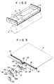
- Its components supported by a common frame 9, as shown in Fig. 2, lens 8 is positioned substantially parallel with the original table 3.
- the photosensitive drum 3 is surrounded by a developing unit 10, a transfer charger 11, a separation charger 12, a cleaning unit 13, and a main charger 14, which are successively arranged in the rotating direction of the photosensitive drum 3, beginning with the position for the projection onto the photosensitive drum 3 by the optical system 4.
- the housing 1 Arranged on a portion of the bottom of the housing 1 are a transfer region 15, defined between the photosensitive drum 3 and the transfer charger 11, and a copy sheet conveyor path 16, extending between the photosensitive drum 3 and the separation charger 12.
- the conveyor path 16 serves to transport a copy sheet P delivered from a paper cassette 17 to a receiving tray 19 through the transfer region 15 and a fixing unit 18.
- the housing 1 further contains a paper-supply roller 20, an aligning roller pair 21, and an exit roller pair 22.
- the photosensitive drum 3 is first charged to a predetermined potential level by corona discharge, using the main charger 14. Thereafter, the photosensitive drum 3 is subjected to an image exposure by the optical system 4, so that an electrostatic latent image corresponding to image information of the original is formed on the surface of the drum 3.
- the electrostatic latent image is supplied with a developing agent by the developing unit 10 and is developed thereby; thus forming a toner image.
- the toner image is transferred to the surface of the copy sheet P at the transfer region 15 by the transfer charger 11.
- the copy sheet P, with the transferred toner image thereon is then separated from the photosensitive drum 3 by the separation charger 12, delivered to the fixing unit 18 for fixing the toner image thereon, and discharged into the receiving tray 19. Meanwhile, the photosensitive drum 3, after the transfer of the toner image, is cleared of those toner particles remaining on its surface without having been transferred to the copy sheet P, by the cleaning unit 13. Thereupon, the machine proceeds to the next copying cycle.
- a moving mechanism 23 for reciprocating the original table 2 back and forth will now be described.
- the two ends of a timing belt 24 are individually fixed to either end of the lower surface of the original table 2 by means of fixtures 25.
- round teeth 26 are formed on the upper surface of the timing belt 24.
- the middle of the timing belt 24 is passed around a drive pulley 27 so that the teeth 26 face the pulley 27.
- the other side of the timing belt 24 is guided by a pair of idlers 28. Namely, the idlers 28 are arranged individually off to the upper right and left of the drive pulley 27 so that the timing belt 24 is stretched between them in substantially a U-shaped configuration.
- the drive pulley 27 is formed with teeth 29 which mate with the teeth 26 of the timing belt 24.
- the drive force of the drive motor 30 is transmitted to the drive pulley 27 by a power transmission system 31.
- the power transmission system 31 consists of a first transmission system 32 which includes gears 33a, 33b and 33c and a first clutch 34 connecting the drive pulley 27 and the motor 30, and a second transmission system 35 which include the gears 33a and 33b, a second clutch 36, and gears 37a, 37b and 37c.
- the drive pulley 27 rotates in the forward direction as the driving force from the drive motor 30 is transmitted successively through the gears 33a, 33b and 33c and the clutch 34 when the first and second clutches 34 and 36 are connected and disconnected, respectively.
- the first and second clutches 34 and 36 may be formed of, e.g., spring clutches or electromagnetic clutches.
- the timing belt 24 consists of a tensile glass-fiber structure 39, a neoprene lining 40 formed on the back of the tensile structure 39, a neoprene tooth portion 41 on the upper side of the tensile structure 39, and a nylon coated portion 42 covering the tooth portion 41.
- the tensile glass-fiber structure 39 Since the tensile glass-fiber structure 39 has very low liability to elongation as well as high tensile strength and high bending durability, accurate pitches can constantly be maintained.
- the neoprene lining 40 is formed from neoprene rubber of improved properties. Therefore, the lining 40 has particularly high wear resistance and is fully resistant to a small quantity of oil as well as to the sun (ultraviolet rays) and ozone.
- the neoprene tooth portion 41 which is fully integral with the neoprene lining 40, is accurately formed from neoprene rubber having high shearing strength and suitable hardness. Since the bottom teeth of the tooth portion 41 are aligned with the pitch line, a change in circular pitch caused by bending is very small.
- the nylon covering 42 is formed of a nylon cloth which covers the neoprene tooth portion 41 for protection. Thus, the coefficient of friction of the nylon covering 42 is small enough to make the engagement resistance very low.
- the timing belt 24 can avoid accumulation of heat attributed to bending, thus enjoying maximum operating efficiency and satisfactory high-speed performance.
- the timing belt 24 used to drive the original table 2 has high rigidity such that vibration of the drive system is eliminated.
- the lens 8 of the optical system 4 is positioned either substantially horizontal to or parallel with the original table 2, the hight H of the housing 1 can be minimized, as shown in Fig. 1.
- the use of the timing belt 24 permits reduction in size of the drive pulley 27, so that the reduction gear ratio can be reduced.
- the drive pulley 27 may be driven directly by, for example, a reversible DC motor 43, as in the first modification of the first embodiment shown in Fig. 7.
- the present invention is described as being applied to an image forming apparatus using the photosensitive drum 3.
- the invention is not limited to this embodiment, and may also be applied to an image forming apparatus which uses a photoelectric conversion element (light receiving element) 44 such as a CCD, as in a second modification shown in Fig. 8.
- the image forming apparatus is described as being constructed so that the optical system and original table are fixed and movable, respectively. Alternatively, however, it may be designed so that the reverse is the case, with the original table and optical system being fixed and movable, respectively.
- a backlash is defined herein as a gap (play) 93 between the belt 91 and the pulley 92 which engage with each other as shown in Fig. 9.
- Backlashes can be either static or dynamic in nature, depending on the number of teeth of the pulley 92. The variation is caused since the pulley 92 is cut by means of a generating rack (hobbing machine) shaped to accomodate the teeth of the belt 91. Theoretically, the greater the number of pulley teeth, the more similar are the pulley teeth to the hob teeth, and also, the smaller is the backlash. In most cases, the size of the dynamic backlash, which depends on the number of pulley teeth, belt width, initial tension, and load, offers no problem. The static backlash is a little smaller than the dynamic one, the latter causing the belt teeth to be distorted by load.
- a tooth 96 of the belt 95 with trapezoidal teeth exhibits a stress distribution as shown in Fig. 10.
- the stress is concentrated on a single spot (point A) where distribution curves meet, so that the tooth 96 of the belt 95 tends to be cut off from point A.
- the propagation of force to the cord 97 becomes uneven, so that the cord 97 is also subjected to concentrated stress near point A.
- the intensively stressed region of the cord 97 is generally the spot where an arcuate motion changes into a substantially straight motion, and, as such, is that area most susceptible to fatigue.
- a tooth 98 of the belt 94 with round teeth if subjected to a force, exhibits a stress distribution as shown in Fig. 11. In this case, there is no concentration of stress as seen on spot A of Fig. 10. Accordingly, the tooth 98 is less susceptible to breakage. Moreover, since the applied stress is dispersed by the cord 99, the cord 99 is less susceptible to fatigue than the cord 97 used with the trapezoidal tooth 96, thereby enabling it to endure greater load.
- Fig. 12 shows stress trajectories.
- stress suddenly increases at a spot substantially halfway between the lateral tooth surfaces, ultimately attaining a maximum level of about 10 striation degrees. This indicates that stress is extremely high in the vicinity of the stressed end of the tooth 96, where the cord 97 is subjected to a maximum stress.
- the stress intensity is distributed evenly, peaking at about 4.5 striation degrees. This indicates that the round tooth 98 has a maximum stress equal to about 45 percent of that of the trapezoidal tooth 96, and is not subject to any local stress concentration.
- the round tooth 98 is less susceptible to shear than the trapezoidal tooth 56, and the load capacity of the cord 99 is about 2.2 times as large as that of the cord 97.
- round-toothed timing belts Beside the features of regular timing belts, round-toothed timing belts have the following features attributed to the aforesaid advantages; i.e., uniform load distribution and even force transmission to the tensile structure.
Landscapes
- Physics & Mathematics (AREA)
- General Physics & Mathematics (AREA)
- Optics & Photonics (AREA)
- Engineering & Computer Science (AREA)
- General Engineering & Computer Science (AREA)
- Mechanical Engineering (AREA)
- Optical Systems Of Projection Type Copiers (AREA)
- Electrophotography Configuration And Component (AREA)
Claims (5)
- Bilderzeugungsgerät, umfassend:
einen Vorlagentisch (2), der eine Vorlage tragen kann;
einen Bildträger (3), an welchem ein latentes Bild entsprechend einem Bild der Vorlage gebildet wird;
ein optisches System (4) zum Anlegen von Licht an die Vorlage auf dem Vorlagentisch (2) und zum Leiten von von der Vorlage reflektiertem Licht auf den Bildträger (3), so daß an der Oberfläche des Bildträgers (3) ein dem Vorlagenbild entsprechendes latentes Bild gebildet wird; und
eine Bewegungseinrichtung (23) zum Bewegen des Vorlagentisches (2) relativ zu dem optischen System (4), um dadurch ein Abtasten der Vorlage auf dem Vorlagentisch (2) mit Licht zu ermöglichen, wobei die Bewegungseinrichtung (23) einen gezahnten Zeitsteuerriemen (24), eine gezahnte Antriebsscheibe (27), die mit den Zeitsteuerriemen in Eingriff steht, und Antriebsmittel (30) zum Drehen der Antriebsscheibe (27) umfaßt,
dadurch gekennzeichnet, daß
der gezahnte Zeitsteuerriemen (24) an beiden Enden an zwei beabstandeten Stellen des Vorlagentisches (2) befestigt ist und daß die gezahnte Antriebsscheibe (27) zwischen den befestigten Enden des Riemens angeordnet ist. - Bilderzeugungsgerät nach Anspruch 1,
dadurch gekennzeichnet, daß der Zeitsteuerriemen (24) mit runden Zähnen gebildet ist, und daß die Antriebsscheibe (27) mit runden Zähnen gebildet ist zum Aufnehmen der Zähne des Zeitsteuerriemens (24). - Bilderzeugungsgerät nach Anspruch 1 oder 2,
dadurch gekennzeichnet, daß die Bewegungseinrichtung (23) ein Paar von Leerrollen (28) aufweist, die zwischen der Antriebsscheibe (27) und dem Vorlagentisch (2) angeordnet sind und den mittleren Teil des Zeitsteuerriemens (24), der rund um die Antriebsscheibe (27) gewickelt ist, derart abstützen, daß dieser mittlere Teil U-förmig ist. - Bilderzeugungsgerät nach irgendeinem der Ansprüche 1 bis 3,
dadurch gekennzeichnet, daß die Antriebsmittel einen reversiblen Motor (43) umfassen. - Bilderzeugungsgerät nach Anspruch 3,
dadurch gekennzeichnet, daß die Antriebsmittel eine Antriebsquelle (30) zum Erzeugen einer Drehkraft in einer Richtung, ein erstes Übertragungssystem (32), welches eine vorbestimmte Anzahl von Übertragungszahnrädern (33a bis 33c) und eine erste Kupplung (34) hat und die Drehkraft von der Antriebsquelle (30) auf die Antriebsscheibe (27) übertragen kann, und ein zweites Übertragungssystem (35) umfaßt, welches Übertragungszahnräder (33a,33b,37a,37b,37c) in einer Anzahl, die um eine ungerade Zahl größer oder kleiner als die Anzahl der Übertragungszahnräder des ersten Ubertragungssystems (32) ist, und eine zweite Kupplung (36) hat; wobei die Antriebsmittel den Vorlagentisch (2) in einer Richtung bewegen können durch Einrücken und Ausrücken der ersten bzw. der zweiten Kupplung (34,36), und in der entgegengesetzten Richtung bewegen können durch Ausrücken und Einrücken der ersten bzw. der zweiten Kupplung (34,36).
Applications Claiming Priority (2)
| Application Number | Priority Date | Filing Date | Title |
|---|---|---|---|
| JP59227413A JPS61105532A (ja) | 1984-10-29 | 1984-10-29 | 画像形成装置 |
| JP227413/84 | 1984-10-29 |
Publications (3)
| Publication Number | Publication Date |
|---|---|
| EP0180143A2 EP0180143A2 (de) | 1986-05-07 |
| EP0180143A3 EP0180143A3 (en) | 1986-12-30 |
| EP0180143B1 true EP0180143B1 (de) | 1991-05-22 |
Family
ID=16860449
Family Applications (1)
| Application Number | Title | Priority Date | Filing Date |
|---|---|---|---|
| EP85113472A Expired - Lifetime EP0180143B1 (de) | 1984-10-29 | 1985-10-23 | Bilderzeugungsgerät |
Country Status (4)
| Country | Link |
|---|---|
| EP (1) | EP0180143B1 (de) |
| JP (1) | JPS61105532A (de) |
| KR (1) | KR900005649B1 (de) |
| DE (1) | DE3582913D1 (de) |
Families Citing this family (2)
| Publication number | Priority date | Publication date | Assignee | Title |
|---|---|---|---|---|
| GB2587297B (en) | 2015-03-31 | 2021-08-04 | Fisher & Paykel Healthcare Ltd | A user interface and system for supplying gases to an airway |
| KR20240157114A (ko) | 2016-08-11 | 2024-10-31 | 피셔 앤 페이켈 핼스케어 리미티드 | 압궤 가능 도관, 환자 인터페이스 및 헤드기어 연결부 |
Family Cites Families (2)
| Publication number | Priority date | Publication date | Assignee | Title |
|---|---|---|---|---|
| US3806239A (en) * | 1972-07-18 | 1974-04-23 | Canon Kk | Original transport device |
| JPS5933442A (ja) * | 1982-08-19 | 1984-02-23 | Toshiba Corp | 画像形成装置 |
-
1984
- 1984-10-29 JP JP59227413A patent/JPS61105532A/ja active Pending
-
1985
- 1985-10-23 EP EP85113472A patent/EP0180143B1/de not_active Expired - Lifetime
- 1985-10-23 DE DE8585113472T patent/DE3582913D1/de not_active Expired - Lifetime
- 1985-10-24 KR KR1019850007875A patent/KR900005649B1/ko not_active Expired
Also Published As
| Publication number | Publication date |
|---|---|
| EP0180143A3 (en) | 1986-12-30 |
| KR860003539A (ko) | 1986-05-26 |
| KR900005649B1 (ko) | 1990-08-01 |
| EP0180143A2 (de) | 1986-05-07 |
| JPS61105532A (ja) | 1986-05-23 |
| DE3582913D1 (de) | 1991-06-27 |
Similar Documents
| Publication | Publication Date | Title |
|---|---|---|
| US5778287A (en) | Electrophotographic imaging apparatus having an improved belt drive system | |
| EP0180143B1 (de) | Bilderzeugungsgerät | |
| CA1218892A (en) | Linear lens array scanning system for a multi- magnification copier | |
| US5030174A (en) | Driving mechanism and image forming apparatus comprising the same | |
| US4073584A (en) | Slit exposure device for use with a stationary original carriage | |
| US4993995A (en) | Toothed-belt fixing mechanism | |
| US5002366A (en) | Scanning apparatus for reading an original image | |
| US4377337A (en) | Document scanning apparatus for an electrostatic copier | |
| US4368976A (en) | Variable speed scanning system | |
| US5482511A (en) | Drive mechanisms | |
| JPH09325580A (ja) | 画像読取装置 | |
| US5075719A (en) | Lens driving device | |
| EP0045102B1 (de) | Schlitzbelichtungseinrichtung | |
| JPH0799425B2 (ja) | 光学式走査装置 | |
| JPH0545949A (ja) | 画像形成装置 | |
| US7356284B2 (en) | Image forming device | |
| JP2539258B2 (ja) | 走査装置 | |
| GB2166557A (en) | Slit-scan photocopying | |
| JPS58122562A (ja) | 複写機の駆動装置 | |
| JPH0816507B2 (ja) | 駆動力伝達機構 | |
| JPH0432664Y2 (de) | ||
| JPH0339786Y2 (de) | ||
| EP0045550A1 (de) | Transportvorrichtung | |
| JPS6012110Y2 (ja) | 原稿走査装置 | |
| JPH0943923A (ja) | 電子写真装置の駆動伝達装置 |
Legal Events
| Date | Code | Title | Description |
|---|---|---|---|
| PUAI | Public reference made under article 153(3) epc to a published international application that has entered the european phase |
Free format text: ORIGINAL CODE: 0009012 |
|
| 17P | Request for examination filed |
Effective date: 19851119 |
|
| AK | Designated contracting states |
Kind code of ref document: A2 Designated state(s): DE FR GB NL |
|
| PUAL | Search report despatched |
Free format text: ORIGINAL CODE: 0009013 |
|
| AK | Designated contracting states |
Kind code of ref document: A3 Designated state(s): DE FR GB NL |
|
| 17Q | First examination report despatched |
Effective date: 19880513 |
|
| GRAA | (expected) grant |
Free format text: ORIGINAL CODE: 0009210 |
|
| AK | Designated contracting states |
Kind code of ref document: B1 Designated state(s): DE FR |
|
| REF | Corresponds to: |
Ref document number: 3582913 Country of ref document: DE Date of ref document: 19910627 |
|
| ET | Fr: translation filed | ||
| PGFP | Annual fee paid to national office [announced via postgrant information from national office to epo] |
Ref country code: FR Payment date: 19911007 Year of fee payment: 7 |
|
| PGFP | Annual fee paid to national office [announced via postgrant information from national office to epo] |
Ref country code: DE Payment date: 19911129 Year of fee payment: 7 |
|
| PLBI | Opposition filed |
Free format text: ORIGINAL CODE: 0009260 |
|
| 26 | Opposition filed |
Opponent name: MANNESMANN AKTIENGESELLSCHAFT Effective date: 19920220 |
|
| RDAG | Patent revoked |
Free format text: ORIGINAL CODE: 0009271 |
|
| STAA | Information on the status of an ep patent application or granted ep patent |
Free format text: STATUS: PATENT REVOKED |
|
| 27W | Patent revoked |
Effective date: 19930225 |
|
| REG | Reference to a national code |
Ref country code: FR Ref legal event code: ST |
|
| PLAB | Opposition data, opponent's data or that of the opponent's representative modified |
Free format text: ORIGINAL CODE: 0009299OPPO |