EP0180177A1 - Dispositif pour le transport des marchandises, notamment pour le chargement de la surface portante d'un véhicule ou d'un conteneur - Google Patents
Dispositif pour le transport des marchandises, notamment pour le chargement de la surface portante d'un véhicule ou d'un conteneur Download PDFInfo
- Publication number
- EP0180177A1 EP0180177A1 EP85113685A EP85113685A EP0180177A1 EP 0180177 A1 EP0180177 A1 EP 0180177A1 EP 85113685 A EP85113685 A EP 85113685A EP 85113685 A EP85113685 A EP 85113685A EP 0180177 A1 EP0180177 A1 EP 0180177A1
- Authority
- EP
- European Patent Office
- Prior art keywords
- loading
- end wall
- side rail
- strand
- trailer
- Prior art date
- Legal status (The legal status is an assumption and is not a legal conclusion. Google has not performed a legal analysis and makes no representation as to the accuracy of the status listed.)
- Granted
Links
Images

Classifications
-
- B—PERFORMING OPERATIONS; TRANSPORTING
- B65—CONVEYING; PACKING; STORING; HANDLING THIN OR FILAMENTARY MATERIAL
- B65G—TRANSPORT OR STORAGE DEVICES, e.g. CONVEYORS FOR LOADING OR TIPPING, SHOP CONVEYOR SYSTEMS OR PNEUMATIC TUBE CONVEYORS
- B65G67/00—Loading or unloading vehicles
- B65G67/02—Loading or unloading land vehicles
- B65G67/04—Loading land vehicles
- B65G67/20—Loading covered vehicles
Definitions
- the invention relates to a device for transporting cargo or general cargo, in particular for loading the wing of a vehicle or a container with stacked packing units, which lie on the bed of a mobile pallet, a roll trailer or the like and can be fed to that wing.
- a method known from DE-OS 28 18 659 and an apparatus of the type mentioned at the outset offer the advantage of simplified loading;
- a pallet of small height which can be moved on a large number of rollers, with general cargo is inserted via a loading ramp or road and removed again at the destination with the general cargo.
- the advantage described in the loading process is offset by the disadvantage that the known pallet increases the loading weight considerably with a reduced loading volume.
- the loading area of the roll trailer or the like is assigned an area that can be moved on it and counter to it and in the direction of travel. It has proven to be advantageous to arrange the surface in the rest position as an end wall on the roll trailer and to connect it with a guide of the roll trailer and at least one actuating member. This end wall can therefore be moved on the loading area and thus move the goods resting on it. This is particularly important if the roll trailer according to the invention for loading loading platforms or the like is pushed onto the latter and then that movable end wall is used to push the goods during the retraction of the roll trailer or the pallet. This considerably simplifies the loading process.
- the movable end wall is of course also suitable as a pulling element for piece goods to be transferred from a shelf to the loading surface of the roll trailer.
- the end wall can be provided with hooks or the like. Holding elements for lashing elements.
- the actuator for moving the end wall is preferably a strand connecting it to a drive, for example a chain, which can advantageously be guided as an infinite loop around rollers.
- the synchronous movement of the pallet on the one hand and the end wall on the other hand is achieved in that the strand is drivingly connected to at least one of the driving rollers of the pallet.
- the loading area of the pallet or of the roll trailer are assigned in a manner known per se which, according to the invention, accommodate the strand; this is preferably attached with its upper run in the side rail, whereas the lower run runs in a profile tube attached to it.
- the side rail and profile tube are extruded in one piece from light metal.
- the side rail offers a cross section of a standing C-profile, the free ends of which are aligned with one another and engage in a circumferential groove of the wheels and thereby produce reliable guidance.
- the front wall is delimited by two side cheeks, each of which extends down to the path of movement of the side rail and is connected to the wheels.
- the side cheeks can be coupled to a run of the strand described above.
- the loading area has support rollers running transversely to the direction of travel as carriers for the cargo, these support rollers preferably being supported at least at one end on the side rail.
- the support rollers can be mounted in a simple manner on the side rails or on the one hand on the side rail and on the other hand on a central support, but it has proven to be particularly advantageous to connect the support rollers at least partially with a drive.
- the drive for the side wall is particularly suitable as the drive, which - connected to one of the castors - drives synchronously with the pallet movement.
- the side wall and idlers are preferably coupled to the drive so that they can move in unison.
- the pallet according to the invention thus has a loading area which is designed as a roller conveyor and also has the described movable wall.
- the carrying rollers are braked during transport thanks to the rope to prevent the load from slipping.
- the end wall guided in longitudinal rails is - as described - preferably connected to a roller or a wheel of the pallet in such a way that the end wall is guided synchronously with the movement of the pallet, but in opposite directions.
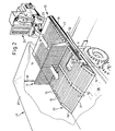
- a pallet 10 of relatively low floor height h with transport wheels 11 arranged at the bottom and with an end wall 12 is provided for the transport of piece goods indicated at 9.
- the loading area 13 of the pallet 10 is designed as a roller conveyor made up of two rows of support rollers 14 — provided transversely to the general direction of travel x; the latter are supported by the interposition of parallel web plates 15 at one end in a side rail 16 and at the other end in a central support 17.
- longitudinally tapered support wedges 19 are articulated by bolts 20, between which support rollers 14 also rest and which with the latter and with an end profile 21 have a foldable ramp 22 surrender.
- FIG. 2 shows that the pallet 10 can be pushed against the general direction of travel x by means of a tractor 24, for example a forklift truck, onto the platform or wing 26 of a truck 27 covered by a tarpaulin 25 - the piece goods 9 conveyed on the support rollers 14 are neglected in Fig. 2 for reasons of clarity relaxed.
- the P-alette 10 is slowly retracted in the direction of travel x and, at the same time, the end wall 12 on the side rails 16 is moved in such a way that it preferably remains on the rear frame 30 of the truck 27 and serves as a push-off device for the piece goods 9 that goes up via that ramp 22 the wing 26 slides.
- the end wall 12 is equipped with wheels 34 at the foot end 31 of side cheeks 32 on axle bolts 33; these each have a circumferential groove 35 into which guide webs 37 of the side rail 16 engage.
- This is of C-shaped cross-section from the central web 39 and legs 40, 41, the latter being integrally formed with the guide webs 32 parallel to the central web 39 and delimiting a guideway for those wheels 34.
- the side walls 32 are connected by transverse profiles 39 and a rod network 50.
- a tubular profile 43 is welded to the lower leg 41 of the side rail 16, in the interior 44 of which the lower run 45 of a link chain 46 runs, the upper run 47 of which is received by the interior 48 of the side rail 16.
- side rail 16 and tubular profile 43 can also be extruded in one piece from light metal.
- the link chain 46 can be provided with a separate drive, but can advantageously be connected to a wheel of the pallet 10; it thus uses the wheel to produce a drive which, when the pallet 10 is moved, guides the end wall 12 at the speed of the pallet movement.
- the side cheek 32 can be braked and fixed by means of a lever 51 - the friction surface between the leg 40 and a braking element on the lever 51 is not shown in the drawing.
- the support rollers 14 are themselves connected in a controlled, movable manner to a drive which prevents the support rollers 14 from rotating during the travel of the pallet 10 and thus serves as a brake. Only at the beginning of the stripping process explained above are the support rollers 14 released from their rest position and rotated toward the ramp 22.
- the end wall 12 is connected to the upper run 47 in a form not shown. If the upper run 47 connected to the support rollers 14 rotates in the direction of arrow y (FIG. 3) - thanks to another coupling form of those support rollers 14 - in the direction of travel x, the end wall 12 is connected to the lower run 45. It is essential in any case that the end wall 12 is guided in the opposite direction at the preferred synchronous speed when the pallet 12 is pulled out.
- a pull chain is indicated at 52, which is fixed with its hook end 53 in the rod network 50; it is conceivable to use the end wall 12 on its way from the ramp 22 to the end edge 23 of the pallet 10 as a pulling element for piece goods to be picked up - those pull chains 52 are fixed to these and the piece goods are thus connected to the rod network 50.
- the piece goods slide over the ramp 22 onto the loading area 13.
Landscapes
- Engineering & Computer Science (AREA)
- Aviation & Aerospace Engineering (AREA)
- Mechanical Engineering (AREA)
- Loading Or Unloading Of Vehicles (AREA)
- Warehouses Or Storage Devices (AREA)
Priority Applications (1)
| Application Number | Priority Date | Filing Date | Title |
|---|---|---|---|
| AT85113685T ATE44372T1 (de) | 1984-10-31 | 1985-10-28 | Vorrichtung zum transport von lade- bzw. stueckgut, insbesondere zum beladen der tragflaeche eines fahrzeuges oder eines containers. |
Applications Claiming Priority (2)
| Application Number | Priority Date | Filing Date | Title |
|---|---|---|---|
| DE8431915U | 1984-10-31 | ||
| DE19848431915U DE8431915U1 (de) | 1984-10-31 | 1984-10-31 | Vorrichtung zum transport von lade- bzw. stueckgut, insbesondere zum beladen der tragflaeche eines fahrzeuges oder eines containers |
Publications (2)
| Publication Number | Publication Date |
|---|---|
| EP0180177A1 true EP0180177A1 (fr) | 1986-05-07 |
| EP0180177B1 EP0180177B1 (fr) | 1989-07-05 |
Family
ID=6772242
Family Applications (1)
| Application Number | Title | Priority Date | Filing Date |
|---|---|---|---|
| EP85113685A Expired EP0180177B1 (fr) | 1984-10-31 | 1985-10-28 | Dispositif pour le transport des marchandises, notamment pour le chargement de la surface portante d'un véhicule ou d'un conteneur |
Country Status (4)
| Country | Link |
|---|---|
| EP (1) | EP0180177B1 (fr) |
| JP (1) | JPS61166434A (fr) |
| AT (1) | ATE44372T1 (fr) |
| DE (2) | DE8431915U1 (fr) |
Cited By (4)
| Publication number | Priority date | Publication date | Assignee | Title |
|---|---|---|---|---|
| WO1987003857A1 (fr) * | 1985-12-23 | 1987-07-02 | Creatum Aktiebolag | Dispositif pour deplacer des marchandises dans la soute d'un avion |
| FR2969132A1 (fr) * | 2010-12-15 | 2012-06-22 | Cauval Ind | Dispositif et procede de chargement de marchandises dans un espace de rangement d'un vehicule de transport. |
| DE102018123739A1 (de) * | 2018-09-26 | 2020-03-26 | Schumacher Packaging Gmbh | Verfahren und Ladeeinrichtung zum heckseitigen Beladen eines LKWs |
| CN114620509A (zh) * | 2022-03-28 | 2022-06-14 | 郑州纬达自动化科技有限公司 | 货物装车用智能化供料系统 |
Families Citing this family (4)
| Publication number | Priority date | Publication date | Assignee | Title |
|---|---|---|---|---|
| JP2565777B2 (ja) * | 1989-10-18 | 1996-12-18 | 富士写真フイルム株式会社 | 間欠搬送装置 |
| DE19856571C2 (de) * | 1998-12-08 | 2003-01-09 | Indumat Gmbh & Co Kg | Transporteinrichtung für Paletten |
| DE102011007862A1 (de) * | 2011-04-21 | 2012-10-25 | Heinz Buse | Logistiksystem und Plattform hierzu |
| KR101877653B1 (ko) | 2013-11-22 | 2018-07-12 | 도요타 스틸 센타 가부시키가이샤 | 반송물의 반송 시스템 및 반송 방법 |
Citations (2)
| Publication number | Priority date | Publication date | Assignee | Title |
|---|---|---|---|---|
| DE2205505B2 (de) * | 1972-02-05 | 1974-10-17 | Foerdertechnische Forschungsgesellschaft Mbh, 2000 Hamburg | Vorrichtung zum Beschicken von Containern mit Stückgut, vorzugsweise beladenen Paletten |
| DE2431542B2 (de) * | 1973-12-13 | 1979-03-22 | Okura Yusoki K.K., Kakogawa, Hyogo (Japan) | Ladevorrichtung für Transportfahrzeuge |
-
1984
- 1984-10-31 DE DE19848431915U patent/DE8431915U1/de not_active Expired
-
1985
- 1985-10-28 AT AT85113685T patent/ATE44372T1/de not_active IP Right Cessation
- 1985-10-28 EP EP85113685A patent/EP0180177B1/fr not_active Expired
- 1985-10-28 DE DE8585113685T patent/DE3571315D1/de not_active Expired
- 1985-10-31 JP JP60245251A patent/JPS61166434A/ja active Pending
Patent Citations (2)
| Publication number | Priority date | Publication date | Assignee | Title |
|---|---|---|---|---|
| DE2205505B2 (de) * | 1972-02-05 | 1974-10-17 | Foerdertechnische Forschungsgesellschaft Mbh, 2000 Hamburg | Vorrichtung zum Beschicken von Containern mit Stückgut, vorzugsweise beladenen Paletten |
| DE2431542B2 (de) * | 1973-12-13 | 1979-03-22 | Okura Yusoki K.K., Kakogawa, Hyogo (Japan) | Ladevorrichtung für Transportfahrzeuge |
Cited By (4)
| Publication number | Priority date | Publication date | Assignee | Title |
|---|---|---|---|---|
| WO1987003857A1 (fr) * | 1985-12-23 | 1987-07-02 | Creatum Aktiebolag | Dispositif pour deplacer des marchandises dans la soute d'un avion |
| FR2969132A1 (fr) * | 2010-12-15 | 2012-06-22 | Cauval Ind | Dispositif et procede de chargement de marchandises dans un espace de rangement d'un vehicule de transport. |
| DE102018123739A1 (de) * | 2018-09-26 | 2020-03-26 | Schumacher Packaging Gmbh | Verfahren und Ladeeinrichtung zum heckseitigen Beladen eines LKWs |
| CN114620509A (zh) * | 2022-03-28 | 2022-06-14 | 郑州纬达自动化科技有限公司 | 货物装车用智能化供料系统 |
Also Published As
| Publication number | Publication date |
|---|---|
| JPS61166434A (ja) | 1986-07-28 |
| ATE44372T1 (de) | 1989-07-15 |
| DE3571315D1 (en) | 1989-08-10 |
| EP0180177B1 (fr) | 1989-07-05 |
| DE8431915U1 (de) | 1985-05-30 |
Similar Documents
| Publication | Publication Date | Title |
|---|---|---|
| WO1989004900A1 (fr) | Systeme de stockage a convoyeur, notamment systeme de stationnement de vehicules | |
| DE3004371A1 (de) | Frachttransporter zum transportieren von ladungen | |
| DE2205505A1 (de) | Verfahren und vorrichtung zum beschicken von containern mit vorzugsweise palettiertem ladegut und zum absetzen des ladegutes auf ladeflaechen von transportfahrzeugen und in lagerhallen | |
| EP0111887B1 (fr) | Méthode et dispositif de chargement d'une caisse de transport ou d'un container | |
| DE2431542A1 (de) | Vorrichtung zum beladen einer ladeflaeche mit waren | |
| EP0668225B1 (fr) | Installation de chargement pour véhicules utilitaires ou rampes | |
| EP0180177B1 (fr) | Dispositif pour le transport des marchandises, notamment pour le chargement de la surface portante d'un véhicule ou d'un conteneur | |
| DE19756551A1 (de) | Be- und Entladesystem für Lastkraftwagen, deren Anhänger, Transportcontainer und dgl. | |
| DE2551019A1 (de) | Vorrichtung zum be- und entladen von transportfahrzeugen | |
| DE19532641C2 (de) | Ziehvorrichtung für Behälter mit Ziehnuten, insbesondere für die Anordnung auf dem Hubtisch eines Regalbediengerätes | |
| EP0116152A2 (fr) | Dispositif pour stocker et retirer des profilés | |
| CH624361A5 (en) | Device for loading and unloading a road-bound or rail-bound vehicle | |
| DE8706291U1 (de) | Entlade- und ggf. Beladevorrichtung | |
| DE644715C (de) | Eisenbahnfahrzeug mit Drehbuehne zum Aufbringen von Strassenfahrzeugen | |
| DE69712280T2 (de) | Verlängerbarer Flachbettanhänger | |
| DE2415760C2 (de) | Einrichtung zur automatischen Be- und Entladung einer Aufzugskabine | |
| DE3102863C2 (de) | Dachträger für Personenkraftwagen zum Transport eines Bootes | |
| DE3538189A1 (de) | Vorrichtung zum transport von lade- bzw. stueckgut, insbesondere zum beladen der tragflaeche eines fahrzeuges oder eines containers | |
| DE19938727A1 (de) | Hebe- und Ladevorrichtung | |
| DE4111523A1 (de) | Flurfoerderfahrzeug | |
| EP0486942B1 (fr) | Dispositif pour charger et décharger un véhicule ferroviaire | |
| EP0098792A1 (fr) | Véhicule utilitaire à carrosserie interchangeable | |
| EP3623218A1 (fr) | Chariot pour un véhicule de transport destiné au transport de conteneurs roulants | |
| DE19604970C1 (de) | Vorrichtung zur Aufgabe von auf dem Boden abgestelltem Stückgut auf eine angrenzende Förderbahn | |
| DE2747250B2 (de) | Einrichtung zum Umsetzen von Stückgut, insbesondere bei Ladeflächen von Lastkraftwagen |
Legal Events
| Date | Code | Title | Description |
|---|---|---|---|
| PUAI | Public reference made under article 153(3) epc to a published international application that has entered the european phase |
Free format text: ORIGINAL CODE: 0009012 |
|
| AK | Designated contracting states |
Kind code of ref document: A1 Designated state(s): AT BE CH DE FR GB IT LI NL SE |
|
| 17P | Request for examination filed |
Effective date: 19860926 |
|
| 17Q | First examination report despatched |
Effective date: 19870422 |
|
| RAP1 | Party data changed (applicant data changed or rights of an application transferred) |
Owner name: ALTHAMMER, HEINZ |
|
| RIN1 | Information on inventor provided before grant (corrected) |
Inventor name: ALTHAMMER, HEINZ |
|
| GRAA | (expected) grant |
Free format text: ORIGINAL CODE: 0009210 |
|
| AK | Designated contracting states |
Kind code of ref document: B1 Designated state(s): AT BE CH DE FR GB IT LI NL SE |
|
| PG25 | Lapsed in a contracting state [announced via postgrant information from national office to epo] |
Ref country code: NL Effective date: 19890705 Ref country code: IT Free format text: LAPSE BECAUSE OF FAILURE TO SUBMIT A TRANSLATION OF THE DESCRIPTION OR TO PAY THE FEE WITHIN THE PRESCRIBED TIME-LIMIT;WARNING: LAPSES OF ITALIAN PATENTS WITH EFFECTIVE DATE BEFORE 2007 MAY HAVE OCCURRED AT ANY TIME BEFORE 2007. THE CORRECT EFFECTIVE DATE MAY BE DIFFERENT FROM THE ONE RECORDED. Effective date: 19890705 Ref country code: GB Effective date: 19890705 Ref country code: FR Free format text: THE PATENT HAS BEEN ANNULLED BY A DECISION OF A NATIONAL AUTHORITY Effective date: 19890705 Ref country code: BE Effective date: 19890705 |
|
| RAP3 | Party data changed (applicant data changed or rights of an application transferred) |
Owner name: ALTHAMMER, HEINZ |
|
| REF | Corresponds to: |
Ref document number: 44372 Country of ref document: AT Date of ref document: 19890715 Kind code of ref document: T |
|
| REF | Corresponds to: |
Ref document number: 3571315 Country of ref document: DE Date of ref document: 19890810 |
|
| PG25 | Lapsed in a contracting state [announced via postgrant information from national office to epo] |
Ref country code: AT Effective date: 19891028 |
|
| EN | Fr: translation not filed | ||
| NLV1 | Nl: lapsed or annulled due to failure to fulfill the requirements of art. 29p and 29m of the patents act | ||
| GBV | Gb: ep patent (uk) treated as always having been void in accordance with gb section 77(7)/1977 [no translation filed] | ||
| PLBE | No opposition filed within time limit |
Free format text: ORIGINAL CODE: 0009261 |
|
| STAA | Information on the status of an ep patent application or granted ep patent |
Free format text: STATUS: NO OPPOSITION FILED WITHIN TIME LIMIT |
|
| PGFP | Annual fee paid to national office [announced via postgrant information from national office to epo] |
Ref country code: DE Payment date: 19900627 Year of fee payment: 5 |
|
| 26N | No opposition filed | ||
| PGFP | Annual fee paid to national office [announced via postgrant information from national office to epo] |
Ref country code: SE Payment date: 19901017 Year of fee payment: 6 |
|
| PGFP | Annual fee paid to national office [announced via postgrant information from national office to epo] |
Ref country code: CH Payment date: 19901105 Year of fee payment: 6 |
|
| PG25 | Lapsed in a contracting state [announced via postgrant information from national office to epo] |
Ref country code: DE Effective date: 19910702 |
|
| PG25 | Lapsed in a contracting state [announced via postgrant information from national office to epo] |
Ref country code: SE Effective date: 19911029 |
|
| PG25 | Lapsed in a contracting state [announced via postgrant information from national office to epo] |
Ref country code: LI Effective date: 19911031 Ref country code: CH Effective date: 19911031 |
|
| REG | Reference to a national code |
Ref country code: CH Ref legal event code: PL |
|
| EUG | Se: european patent has lapsed |
Ref document number: 85113685.3 Effective date: 19920510 |