EP0180345A2 - Procédé et appareil pour le codage et décodage des signaux d'images - Google Patents
Procédé et appareil pour le codage et décodage des signaux d'images Download PDFInfo
- Publication number
- EP0180345A2 EP0180345A2 EP85307095A EP85307095A EP0180345A2 EP 0180345 A2 EP0180345 A2 EP 0180345A2 EP 85307095 A EP85307095 A EP 85307095A EP 85307095 A EP85307095 A EP 85307095A EP 0180345 A2 EP0180345 A2 EP 0180345A2
- Authority
- EP
- European Patent Office
- Prior art keywords
- coding
- circuit
- signal
- decoding
- picture signal
- Prior art date
- Legal status (The legal status is an assumption and is not a legal conclusion. Google has not performed a legal analysis and makes no representation as to the accuracy of the status listed.)
- Granted
Links
- 238000000034 method Methods 0.000 title claims abstract description 12
- 239000013598 vector Substances 0.000 claims abstract description 43
- 238000006243 chemical reaction Methods 0.000 claims abstract description 41
- 230000033001 locomotion Effects 0.000 claims abstract description 41
- 230000005540 biological transmission Effects 0.000 claims abstract description 18
- 238000013139 quantization Methods 0.000 claims description 12
- 238000001514 detection method Methods 0.000 claims description 9
- 230000000694 effects Effects 0.000 claims description 7
- 230000003252 repetitive effect Effects 0.000 claims description 5
- 230000006870 function Effects 0.000 claims description 3
- 230000003111 delayed effect Effects 0.000 claims description 2
- 241000592503 Speea Species 0.000 claims 1
- 230000000977 initiatory effect Effects 0.000 claims 1
- 230000000295 complement effect Effects 0.000 abstract 1
- 238000010586 diagram Methods 0.000 description 5
- 230000008901 benefit Effects 0.000 description 3
- 238000004891 communication Methods 0.000 description 3
- 230000006835 compression Effects 0.000 description 3
- 238000007906 compression Methods 0.000 description 3
- 230000007704 transition Effects 0.000 description 2
- 238000007796 conventional method Methods 0.000 description 1
- 238000005516 engineering process Methods 0.000 description 1
- 230000006872 improvement Effects 0.000 description 1
- 238000012544 monitoring process Methods 0.000 description 1
- 238000012545 processing Methods 0.000 description 1
- 230000004044 response Effects 0.000 description 1
Images


Classifications
-
- H—ELECTRICITY
- H04—ELECTRIC COMMUNICATION TECHNIQUE
- H04N—PICTORIAL COMMUNICATION, e.g. TELEVISION
- H04N19/00—Methods or arrangements for coding, decoding, compressing or decompressing digital video signals
- H04N19/50—Methods or arrangements for coding, decoding, compressing or decompressing digital video signals using predictive coding
- H04N19/503—Methods or arrangements for coding, decoding, compressing or decompressing digital video signals using predictive coding involving temporal prediction
- H04N19/51—Motion estimation or motion compensation
-
- H—ELECTRICITY
- H04—ELECTRIC COMMUNICATION TECHNIQUE
- H04N—PICTORIAL COMMUNICATION, e.g. TELEVISION
- H04N19/00—Methods or arrangements for coding, decoding, compressing or decompressing digital video signals
- H04N19/30—Methods or arrangements for coding, decoding, compressing or decompressing digital video signals using hierarchical techniques, e.g. scalability
Definitions
- the present invention relates to a coding technology for picture signals.
- Picture signals especially television signals which are typical motion picture signals, present a high correlation between frames i.e. high interframe correlation.
- interframe predictive coding is the simplest system among the methods of utilizing interframe correl-ation. See H. Kaneko and T. Isniguro "Digital television transmission using bandwidth compression techniques", IEEE Communication Magazine, July 1980, pp. 14 - 22. With this system, the smaller the number of moving portions included in a frame, the greater the compression ratio becomes. However, when the extent of motion (area, or velocity etc.) is large, a large degree of compression cannot be expected.
- a "Motion-compensated interframe predictive coding system” which always realizes adaptively an optimum prediction with respect to moving portions, even when they are included, by utilizing a motion vector indicative of moving speed and direction of the moving portions.
- This motion-compensated interframe coding method makes it possible to achieve a ccnpression to a substantial extent even if moving portions are included in the frame.
- an example of the motion-compensated interframe coding system is described in USP No. 4,460,923 assigned to the same applicant as the present invention. This patent discloses a predictive coding system capable of remarkably improving coding efficiency especially where the transmission speed is low.
- variable length code e.g. Huffman code etc. is often used.
- the coding procedure comprises providing in succession a synchronizing code (e.g.
- an object of the present invention is to provide a code conversion system suitable for a low bit transmission rate of picture signals.
- a code conversion method for a picture signal wherein an operation is made to select a coding parameter by using N scanning lines (N is a positive integer) of the picture signal as a unit so as to encode the picture signal by using the coding parameter, characterized in that when coding operations with respect to the picture signal carried out every N scanning lines are repeated in succession to provide the same coding result, an operation is made to encode a repetition number of the coding operations.
- an encoder for a picture signal comprising: code conversion means responsive to successive picture signals correlative with each other to apply a predetermined code conversion based on quantization to each picture signal so as to limit the output level of the picture signal on the basis of a quantization for selecting one of quantization characteristics in accordance with a coding parameter selected using N (integer: N > 1) scanning lines as a unit; first coding means operative to encode information indicative of the coding parameter every N scanning lines; second coding means operative to encode the picture signal outputted from the code conversion means every N scanning lines; judging means provided in the first coding means to judge as to whether an output of the first coding means is the same as that of immediately preceding N scanning lines to produce a coincidence signal when both the outputs are coincident with each other; third coding means, provided in the first coding means, being responsive to said coincident signal from the judging means to encode repetition number of the coding operations carried out everyN scanning lines; and multiplexer means operative to multiplex output
- a decoder for a picture signal, the decoder responsive to the picture signal coded so that its output level is limited to a predetermined range in accordance with a coding parameter selected using N scanning lines as a unit, wherein when coding operations with respect to the picture signal carried out every N scanning lines are repeated in succession, the coded picture signal includes a codeo repetition number of the coding operations, the decoder comprising means responsive to information indicating the coding parameter, the picture signal and the number of the successive repetitive operations to separate them from each other, first decoding means operative to decode the coding parameter from the separating means, second decoding means operative to decode the coded picture signal from the separating means using an output from the first decoding means, and control means responsive to the information indicative of the coded number of the successive repetitive operations from the separating means, thus outputting a decoded picture signal from the second decoding means by the decoded repetition number of the coding operations.
- the code combination labelled B in Fig. 1 is based on the system which has been employed in the art as previously described. There are instances where loss occurs when the synchronizing code, the line synchronizing signal and the coding mode signal are always code-converted in a fixed manner and transmitted. In the case where the subsequent motion vector and prediction error can be expressed as a fixed repetition thereof, in general, as a repetition every N scanning lines under a certain coding mode signal, execution of code conversion every N scanning lines is redundant. In such a case, an operation is effective to generate a code indicative of the subsequent repetition number after the code conversion is initially carried out based on the code combination B shown in Fig.
- an operation is effected to express that the completely still condition is mode-converted by using 1 bit within the coding mode signal subsequent to the synchronizing code and the line synchronization, thereafter to add, subsequent to the coding mode signal, a code-converted repetition number m indicating that the status of the coding mode signal continues during m x N scanning lines.
- the added number m represents a run length in Fig. 1.
- the quantity of code required at this time per the concerned scanning lines is (8 x 4)/(m x N) bits on the assumption that 8 bits are required for expressing the repetition number m.
- N 8
- the quantity of code is expressed by 4/m bits/scanning line.
- 525/8 ⁇ 65 can be expressed as the repetition number m.
- the repetition number m can be expressed still using 8 bits, with the result that 8 x 4 (bit/frame) is sufficient in the same manner.
- the ratio of the quantity of codes in connection with the two cases is 32/1575 ⁇ 1/49.
- the system according to the present invention makes it possible to greatly reduce the quantity of code required for expressing the completely still condition by the same one frame.
- the completely still condition described as an example is a condition actually occurring in the case of field repetition which is representative technique usually used when occurrence of information at the time of coding is excessive or in the case where coding is stopped.
- transmission bit rate is low or a picture includes a sudden movement
- the occurrence frequency of the completely still condition is increased.
- a frame synchronization indicating the begining of frame is inserted instead of the line sychronization in A shown in Fig. 1 to effect code conversion by using the above-mentioned m indicating 65 as a repetition number, thus making it possible to execute code conversion of the entire one frame.
- encoder circuitry will be described.
- an input picture signal is supplied to a vector detection circuit 10 and a predictive coding circuit 20 via a line 1000.
- the vector detection circuit 10 is operative to detect speed and direction of a motion i.e. a motion vector within a frame to deliver the motion vector to the predictive coding circuit 20 and a variable length coding circuit 30 via a line 2000.
- the predictive coding circuit 20 is operative to adaptively vary a delay time between successive frames in accordance with the motion indicated by the motion vector to produce a prediction signal, thus effecting a predictive coding using the prediction signal.
- a prediction error signal is fed to the variable length coding circuit 30 via a line 2030.
- the prediction error signal has been ordinarily subjectedto processing called "quantization" to limit the number of possible output levels.
- a plurality of quantization characteristics are prepared.
- an operation is made to select one of the quantization characteristics in accordance with a coding control signal delivered via a line 4000 to use the selected one.
- the coding control signal includes information instructing control e.g. dropping of picture element or scanning line or a repetition of frame of field etc.
- the coding control signal varies per unit of N scanning lines.
- a coding control circuit 40 is operative to produce this coding control signal by monitoring occupancy of a buffer memory (designated by reference numeral 304 in Fig. 3A) incorporated in the variable length coding circuit 30.
- Such a coding control signal delivered via the line 4000 is code-converted in the variable length coding circuit 30.
- the predictive coding circuit 20 is not necessarily provided with a function to produce a prediction signal corresponding to the motion vector. For instance, prediction constantly using picture elements in a frame preceding by one, i.e. interframe prediction may be used.
- the above-mentioned predicitive cooing circuit may be replaced with a code converter circuit by using an orthogonal transform e.g. Hadamard Transform or Cosine Transform etc. Further, an orthogonal transform may be applied to a prediction error signal obtained by predictive coding. In such a case, quantization ireffected with respect to a transform coefficient obtainea, thus to deliver a quantized conversion coefficient to the variable length coding circuit 30 via the line 2030.
- the variable length coding circuit 30 receives a coding control signal, a prediction error signal (or a conversion coefficient) and a motion vector and applies code conversion to these signals to carry out a matching between occurrence speed of information and transmission bit rate thereof when transferring them to a transmission path 3000.
- information indicative of occupancy of the buffer memory (304, in Fig. 3A) is supplied to the coding control circuit 40 via a line 3040.
- the code train inversely converted is separated into a coding control signal, a prediction error signal (or a conversion coefficient) and a motion vector. They are outputted from the variable length decoding circuit 50 via lines 5061, 5062 and 5063, respectively.
- a predictive decoding circuit 60 is operative to decode/reproduce a picture signal on the basis of inverse operation of the predictive coding circuit 20 to output the picture signal via a line 60QG.
- the predictive decoding circuit 60 would be replaced by the function of orthogonal inverse transform.
- variable length coding circuit 30 and the variable length decoding circuit 50 will be described in detail with reference to Figs. 3A and 3B.
- Fig. 3A illustrates details of the variable length coding circuit 30.
- a coding control signal is supplied to an M (mode) coding circuit 300 and an e (error) coding circuit 302 via the line 4000.
- the operation of the M coding circuit 300 will be described in detail later.
- An output from the M coding circuit 300 is supplied to a multiplexer (MPX) 303 via a line 3034, and at the same time information indicating that code conversion is completed is fed to a V (vector) coding circuit 301 via a line 3031. Subsequent to this, the V coding circuit 301 is operative to carry out code conversion of a motion vector supplied via the line 2000.
- MPX multiplexer
- the motion vector thus code-converted is supplied to the MPX 303 via a line 3133 and at the same time information indicating that this code conversion is completed is fed to the e coding circuit 302 via a line 3132.
- motion vectors within N scanning lines are collectively subject to code conversion.
- the motion vectors thus coded are arranged subsequent to the coding mode as indicated by B in Fig. 1.
- the e coding circuit 302 is operative to apply code conversion to the prediction error signal (or the transform coefficient) supplied via a line 2030 in accordance with a coding mode signal.
- the code-converted signal is supplied to the MPX 303 via a line 3233 and at the same time information indicating that code conversion is completed is supplied to the M coding circuit 300 via a line 3230.
- the MPX 303 is operative to multiplex three signals e.g. the line synchronization, the coding mode signal and the run length as indicated by A in Fig. 1 or four signals e.g. the line synchronization, the coding mode signal, the motion vector and the prediction error code.
- a multiplexed signal is supplied to the buffer memory 304 and undergoes speed matching, thereafter being outputted to the transmission path 3000.
- Information indicative of buffer occupancy (indicating what degree the memory capacity is used) of the memory 304 is supplied to the coding control circuit 40.
- Fig. 3B shows details of the variable length decoding cirucit 50.
- a converted code train supplied via . the transmission path 3000 once undergoes speed matching in the buffer memory 503. Thereafter, the signal thus obtained is supplied to an M decoding circuit 500, a V decoding circuit 501 and an e decoding circuit 502.
- the M decoding circuit 500 is operative to decode line synchronization and coding mode, and to judge whether there exists a code indicating how many times the same code conversions are repeated per unit of the N scanning lines to decode the code when present. In the case where it is judged that the code indicative of the repetition number is included (see code train A in Fig. 1), a decoded coding mode signal is outputted via a line 5061.
- an instruction for repeatedly outputting the same decoded results by a repetition number of decoding operations is supplied to the V decoding circuit 501 and the e decoding circuit 502 via a line 5050.
- a coding stop so-called "stop"
- both the motion vector and the prediction error signal are ordinarily expressd by zero.
- the M decoding circuit 500 instructs the V decoding circuit 501 to initiate the decoding operation of the motion vector via a line 5051.
- the V decoding circuit 501 is operative to decode a motion vector to output the decoded motion vector via a line 5063. After the delivery of the decoded motion vector is completed, the V decoding circuit 501 instructs the e decoding circuit 502 to initiate the decoding operation of the prediction error signal via a line 5152. The decoded prediction error signal is outputted via a line 5062. It is required to constitute the V decoding circuit 501 and the e decoding circuit 502 so that they repeat delivery of the same outputs under the control of the M decoding circuit 500. Ordinarily, they are configured so that zero can be outputted as previously mentioned. When the decoding operation of the prediction error signal is completed in the e decoding circuit 502, a signal indicative of decoding completion is outputted to the M decoding circuit 500.
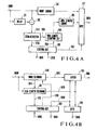
- the M encoaing circuit 300 and the M decoding circuit 500 will be described in detail with reference to Figs. 4A and 4B.
- Fig. 4A illustrates details of the M coding circuit 300.
- a coding mode signal supplied via the line 4000 is fed to a mode coding circuit 310, a subtractor 312 and a delay circuit 311 at the same time.
- the mode encoding circuit 310 is operative to add a line synchronization to an input encoding mode signal to effect code conversion thereof, thus to deliver a coded output to a multiplexer (MPX) circuit 317.
- the subtractor 312 is operative to produce a difference between a current coding mode signal and a coding mode signal delayed by a time required for scanning the N scanning lines.
- a zero detection circuit 313 is operative to carry out a zero detection, i.e., detect a coincidence based on an output from the subtractor 312.
- the zero detection circuit 313 When the zero detection circuit 313 detects zero, it instructs a run length counting circuit 314 to increase a counted value by one via a line 1314, and to transmit information regarding whether zero is present or not to a control circuit 316 via a line 1316.
- the run length counting circuit 314 counts numbers to be repeated in accordance with a counter start/stop instruction supplied via a line 1614.
- the run length counting circuit 314 receives a stop instruction, it delivers a counted result to the run length encoding circuit 315.
- the run length encoding circuit 315 is operative to execute a code conversion in respect of an input count result to supply it to the MPX circuit 317.
- the control circuit 316 controls a counting operation of the run length and a multiplexing operation.
- the control circuit 316 is configured to receive zero or non-zero via the line 1316. When transition from non-zero to zero is carried out, the control circuit 316 instructs the run length counting circuit 314 to initiate counting operation via a line 1614, while when transition from zero to non-zero is carried out, it instructs the circuit 314 to stop the counting operation via the line 1614.
- the control circuit 316 is operative to control the MPX circuit 317 via a line 1617 in such a manner that during run length counting operation, it does not multiplex an output from the mode coding circuit 310, and only when run length counting operation is completed, it multiplexes an output from the run length encoding circuit 315.
- the control circuit 316 instructs the V coding circuit 301 to initiate coding of a motion vector via a line 3031 after the subsequent mode is outputted.
- the run length counting is not carried out, it instructs the V coding circuit 301 to effect the same operation each time the mode code is outputted.
- the V encoding circuit 301 has no output, which corresponds to zero output.
- the e encoding circuit 302 has no output, which corresponds to zero output since the completion of the code conversion of a motion vector from the V encoding circuit 301 is not instructed during run length counting operation.
- the control circuit 316 is restarted in response to a signal indicating completion of code conversion of a prediction error signal supplied from the e coding circuit 302 via a line 3230.
- the line synchronization and the coding mode signal which are multiplexed or the line synchronization, the coding mode signal and a signal indicative of repetition numbers which are multiplexed are fed to the MPX 303 via a line 3034.
- Fig. 4B illustrates details of the M decoding circuit 500.
- An output from the buffer memory 503 supplied via a line 5030 is fed to a mode decoding circuit 510 and a run length decoding circuit 511.
- the mode decoding circuit 510 is operative to decode the line synchronization and the coding mode signal to supply a decoded result to a latch circuit 513 via a line 1013.
- the run length decoding circuit 511 is operative to decode the code, thereafter to deliver information indicative of the run length to a control circuit 512 via a linelll2.
- the run length decoding circuit 511 instructs the latch circuit 513 to latch the coding mode signal just aecoded via a line 5110, and further allows a gate circuit 514 to produce a signal instructing repetitive operations corresponding to a repetition number.
- the control circuit 512 is operative to count a time corresponding to the repetition number supplied. When the counted time has elapsed, the control circuit 512 instructs the latch circuit 513 to stop a latching operation, and to instruct the gate circuit 514 to stop an output of the signal indicative of repetition number via a line 5120.
- the control circuit 512 also informs the mode decoding circuit 510 via a line 1210 that repetitive operations are completed and instructs it to execute a decoding operation of the coding mode signal.
- the run length decoding circuit 511 When there is no information indicative of run length subsequent to the coding mode signal, the run length decoding circuit 511 does not supply any signals to the latch circuit 513 and the gate circuit 514, and informs the control circuit 512 via a line ll12 that decoding of the coding mode signal is completed.
- the run length decoding circuit 511 instructs the V decoding circuit 501 to initiate decoding of a motion-vector via a line 5051.
- the operation of the control circuit 512 is initiated by a signal indicating that decoding of the prediction error signal supplied via a line 5250 from the e encoding circuit 502 is completed, and is once completed by an instruction to initiate decoding operation of a motion vector with respect to the V decoding circuit 501.
- a signal indicative of repetition number is outputted from the gate circuit 514 via a line 5050.
- the repetition signal is considered to be inactive signal, which does not affect the V decoding circuit 501 and the e decoding circuit 502.
- the repetition signal is considered to be an active signal, which instructs that both outputs from the V decoding circuit 501 and the e decoding circuit 502 are to be zero.
- the code conversion scheme according to the present invention is to encode a repetition number instead of repeating encoding operations one by one when the same codec outputs repeatedly occur. Accordingly, this reduces the quantity of information required, ano when encoding and transmitting a picture signal at a very slow transmission bit rate, this makes it possible to additionally assign a transmission bit rate to encoding of the original picture portion by a reduced quantity, resulting in improvement in picture quality. For this reason, when the present invention is put into practice, it can provide an increasing advantage as the transmission rate is lowered.
- the present invention is applicable not only to the predictive encoding system described as the embodiment but also to an orthogonal transform in the same manner. Accordingly, the present invention can extend fields of applications, providing excellent advantages when applied to practical use.
Landscapes
- Engineering & Computer Science (AREA)
- Multimedia (AREA)
- Signal Processing (AREA)
- Compression Or Coding Systems Of Tv Signals (AREA)
- Compression, Expansion, Code Conversion, And Decoders (AREA)
Applications Claiming Priority (4)
| Application Number | Priority Date | Filing Date | Title |
|---|---|---|---|
| JP59208624A JPS6187487A (ja) | 1984-10-04 | 1984-10-04 | 画像信号の符号変換方法 |
| JP208625/84 | 1984-10-04 | ||
| JP208624/84 | 1984-10-04 | ||
| JP59208625A JPS6187488A (ja) | 1984-10-04 | 1984-10-04 | 画像の符号化および復号化装置 |
Publications (3)
| Publication Number | Publication Date |
|---|---|
| EP0180345A2 true EP0180345A2 (fr) | 1986-05-07 |
| EP0180345A3 EP0180345A3 (en) | 1987-05-13 |
| EP0180345B1 EP0180345B1 (fr) | 1990-03-21 |
Family
ID=26516940
Family Applications (1)
| Application Number | Title | Priority Date | Filing Date |
|---|---|---|---|
| EP85307095A Expired EP0180345B1 (fr) | 1984-10-04 | 1985-10-03 | Procédé et appareil pour le codage et décodage des signaux d'images |
Country Status (4)
| Country | Link |
|---|---|
| US (1) | US4727421A (fr) |
| EP (1) | EP0180345B1 (fr) |
| CA (1) | CA1273104A (fr) |
| DE (1) | DE3576779D1 (fr) |
Cited By (6)
| Publication number | Priority date | Publication date | Assignee | Title |
|---|---|---|---|---|
| EP0309280A1 (fr) * | 1987-09-23 | 1989-03-29 | BRITISH TELECOMMUNICATIONS public limited company | Codeur vidéo |
| EP0274861A3 (en) * | 1986-12-08 | 1990-12-27 | Northern Telecom Limited | Two-channel coding of digital signals |
| AU619504B2 (en) * | 1987-09-23 | 1992-01-30 | British Telecommunications Public Limited Company | Video coder |
| US5371811A (en) * | 1987-07-09 | 1994-12-06 | British Telecommunications Public Limited Company | Data encoding |
| USRE34824E (en) * | 1987-09-23 | 1995-01-10 | British Telecommunications Public Limited Company | Video coder |
| US5563920A (en) * | 1993-02-17 | 1996-10-08 | Zenith Electronics Corporation | Method of processing variable size blocks of data by storing numbers representing size of data blocks in a fifo |
Families Citing this family (13)
| Publication number | Priority date | Publication date | Assignee | Title |
|---|---|---|---|---|
| NL8700565A (nl) * | 1987-03-10 | 1988-10-03 | Philips Nv | Televisiesysteem waarin aan een transformatiekodering onderworpen gedigitaliseerde beeldsignalen worden overgebracht van een kodeerstation naar een dekodeerstation. |
| US5157743A (en) * | 1987-10-28 | 1992-10-20 | Canon Kabushiki Kaisha | Image information coding apparatus |
| US4985700A (en) * | 1988-03-01 | 1991-01-15 | Canon Kabushiki Kaisha | Variable-length coding/decoding device |
| US4901085A (en) * | 1988-09-23 | 1990-02-13 | Spar Aerospace Limited | Divided LLBFN/HMPA transmitted architecture |
| EP0368400B1 (fr) * | 1988-11-08 | 1995-05-10 | Laboratoires D'electronique Philips | Codage, décodage et système de transmission d'images de télévision |
| FR2644027A1 (fr) * | 1989-03-03 | 1990-09-07 | Labo Electronique Physique | Dispositif de codage et de decodage d'images de television, systeme de transmission d'images de television incorporant de tels dispositifs, et etages d'emission et de reception d'un tel systeme |
| JP3083344B2 (ja) * | 1990-05-25 | 2000-09-04 | ヒューレット・パッカード・カンパニー | データの圧縮及び圧縮解除方法 |
| EP0744869B1 (fr) * | 1990-12-28 | 2000-03-22 | Canon Kabushiki Kaisha | Appareil de traitement d'image |
| JP2833236B2 (ja) * | 1991-01-31 | 1998-12-09 | 日本電気株式会社 | 画像の予測符号化方式 |
| KR950004129B1 (ko) * | 1992-05-19 | 1995-04-25 | 주식회사금성사 | 가변장 부호 복호기 |
| JPH06217288A (ja) * | 1993-01-20 | 1994-08-05 | Matsushita Electric Ind Co Ltd | 動きベクトル符号化方法およびその装置 |
| US5784570A (en) * | 1995-04-07 | 1998-07-21 | At&T Corp | Server for applying a recipient filter and compressing the input data stream based upon a set of at least one characteristics in a multiuser interactive virtual environment |
| US8502708B2 (en) * | 2008-12-09 | 2013-08-06 | Nippon Telegraph And Telephone Corporation | Encoding method and decoding method, and devices, program and recording medium for the same |
Family Cites Families (8)
| Publication number | Priority date | Publication date | Assignee | Title |
|---|---|---|---|---|
| US3767847A (en) * | 1971-07-01 | 1973-10-23 | Bell Telephone Labor Inc | Frame-to-frame redundancy reduction system which transmits an intraframe coded signal |
| DE2703909C2 (de) * | 1975-09-18 | 1983-09-08 | Siemens AG, 1000 Berlin und 8000 München | Bildübertragungsanlage |
| US4418409A (en) * | 1980-03-07 | 1983-11-29 | Ibm Corporation | Byte data activity compression |
| US4409623A (en) * | 1981-01-31 | 1983-10-11 | Nippon Telegraph & Telephone Public Corporation | Method and equipment for processing gray scale facsimile signal |
| US4475127A (en) * | 1981-02-24 | 1984-10-02 | Nippon Electric Co., Ltd. | System for transmitting a video signal with short runs avoided in a signal encoded from the video signal |
| US4460923A (en) * | 1981-06-01 | 1984-07-17 | Nippon Electric Co., Ltd. | Predictive coding system for television signals |
| FI75072C (fi) * | 1982-07-23 | 1988-04-11 | British Telecomm | Dataoeverfoeringssystem. |
| JPH0644815B2 (ja) * | 1984-04-27 | 1994-06-08 | 日本電気株式会社 | 動物体の動き内挿装置 |
-
1985
- 1985-10-02 US US06/783,198 patent/US4727421A/en not_active Expired - Lifetime
- 1985-10-03 CA CA000492149A patent/CA1273104A/fr not_active Expired
- 1985-10-03 EP EP85307095A patent/EP0180345B1/fr not_active Expired
- 1985-10-03 DE DE8585307095T patent/DE3576779D1/de not_active Expired - Lifetime
Cited By (10)
| Publication number | Priority date | Publication date | Assignee | Title |
|---|---|---|---|---|
| EP0274861A3 (en) * | 1986-12-08 | 1990-12-27 | Northern Telecom Limited | Two-channel coding of digital signals |
| US5371811A (en) * | 1987-07-09 | 1994-12-06 | British Telecommunications Public Limited Company | Data encoding |
| EP0309280A1 (fr) * | 1987-09-23 | 1989-03-29 | BRITISH TELECOMMUNICATIONS public limited company | Codeur vidéo |
| WO1989003153A1 (fr) * | 1987-09-23 | 1989-04-06 | British Telecommunications Public Limited Company | Codeur video |
| US4985766A (en) * | 1987-09-23 | 1991-01-15 | British Telecommunications Public Limited Company | Video coder |
| AU619504B2 (en) * | 1987-09-23 | 1992-01-30 | British Telecommunications Public Limited Company | Video coder |
| USRE34824E (en) * | 1987-09-23 | 1995-01-10 | British Telecommunications Public Limited Company | Video coder |
| US5563920A (en) * | 1993-02-17 | 1996-10-08 | Zenith Electronics Corporation | Method of processing variable size blocks of data by storing numbers representing size of data blocks in a fifo |
| USRE41569E1 (en) * | 1993-02-17 | 2010-08-24 | Lg Electronics, Inc. | Method of processing variable size blocks of data by storing numbers representing size of data blocks in a fifo |
| USRE42147E1 (en) | 1993-02-17 | 2011-02-15 | Lg Electronics, Inc. | Method of processing variable size blocks of data by storing numbers representing size of data blocks in a fifo |
Also Published As
| Publication number | Publication date |
|---|---|
| EP0180345A3 (en) | 1987-05-13 |
| US4727421A (en) | 1988-02-23 |
| DE3576779D1 (de) | 1990-04-26 |
| EP0180345B1 (fr) | 1990-03-21 |
| CA1273104A (fr) | 1990-08-21 |
Similar Documents
| Publication | Publication Date | Title |
|---|---|---|
| EP0180345A2 (fr) | Procédé et appareil pour le codage et décodage des signaux d'images | |
| US4731664A (en) | Method and arrangement for refreshing a frame memory in an interframe encoding system | |
| JP3807342B2 (ja) | デジタル信号符号化装置、デジタル信号復号装置、デジタル信号算術符号化方法、およびデジタル信号算術復号方法 | |
| EP0550843A1 (fr) | Multiplexer statistique pour un système de compression d'image multicanal | |
| US5856988A (en) | Method and apparatus for data transmission | |
| CA2108338A1 (fr) | Codeur adaptatif pour coder des signaux video sur deux couches dans les reseaux mta (a mode de transfert asynchrone) | |
| GB2309611A (en) | A motion video compression system with buffer empty/fill look-ahead bit allocation | |
| HK112397A (en) | Signal coding | |
| US5566192A (en) | Variable-length decoder for bit-stuffed data | |
| US5424733A (en) | Parallel path variable length decoding for video signals | |
| JPS61118085A (ja) | 画像信号の符号化方式およびその装置 | |
| EP0708566A2 (fr) | Méthode pour contrÔler la mémoire tampon d'un codeur de données vidéo | |
| EP0631440A2 (fr) | Appareil pour le décodage en parallèle de signaux d'image codés à longueur variable | |
| US4780760A (en) | DPCM system with interframe motion indicator signal | |
| US7522665B2 (en) | Mobile terminal with camera | |
| US4679081A (en) | System for coding video signal in block unit | |
| US5644660A (en) | Method and apparatus for efficiently transmitting forced updates in a moving picture codec | |
| JP2520404B2 (ja) | 圧縮復号化装置 | |
| GB2261567A (en) | Method and device for image coding of a video signal | |
| US4802004A (en) | Predictive coding system for TV signals | |
| EP0860077A1 (fr) | Procede d'estimation de mouvement | |
| US6188791B1 (en) | Image processing apparatus | |
| WO1997038532A1 (fr) | Commande de tampon dans un systeme de transmission de donnees codees | |
| JPH0289472A (ja) | 画像符号化伝送装置 | |
| JPH0686253A (ja) | 動画像データ伝送装置 |
Legal Events
| Date | Code | Title | Description |
|---|---|---|---|
| PUAI | Public reference made under article 153(3) epc to a published international application that has entered the european phase |
Free format text: ORIGINAL CODE: 0009012 |
|
| 17P | Request for examination filed |
Effective date: 19851014 |
|
| AK | Designated contracting states |
Kind code of ref document: A2 Designated state(s): DE FR GB IT |
|
| PUAL | Search report despatched |
Free format text: ORIGINAL CODE: 0009013 |
|
| AK | Designated contracting states |
Kind code of ref document: A3 Designated state(s): DE FR GB IT |
|
| 17Q | First examination report despatched |
Effective date: 19880824 |
|
| GRAA | (expected) grant |
Free format text: ORIGINAL CODE: 0009210 |
|
| AK | Designated contracting states |
Kind code of ref document: B1 Designated state(s): DE FR GB IT |
|
| REF | Corresponds to: |
Ref document number: 3576779 Country of ref document: DE Date of ref document: 19900426 |
|
| ET | Fr: translation filed | ||
| ITF | It: translation for a ep patent filed | ||
| PLBE | No opposition filed within time limit |
Free format text: ORIGINAL CODE: 0009261 |
|
| STAA | Information on the status of an ep patent application or granted ep patent |
Free format text: STATUS: NO OPPOSITION FILED WITHIN TIME LIMIT |
|
| 26N | No opposition filed | ||
| ITTA | It: last paid annual fee | ||
| PGFP | Annual fee paid to national office [announced via postgrant information from national office to epo] |
Ref country code: GB Payment date: 19971001 Year of fee payment: 13 |
|
| PGFP | Annual fee paid to national office [announced via postgrant information from national office to epo] |
Ref country code: FR Payment date: 19971010 Year of fee payment: 13 |
|
| PGFP | Annual fee paid to national office [announced via postgrant information from national office to epo] |
Ref country code: DE Payment date: 19971230 Year of fee payment: 13 |
|
| PG25 | Lapsed in a contracting state [announced via postgrant information from national office to epo] |
Ref country code: GB Free format text: LAPSE BECAUSE OF NON-PAYMENT OF DUE FEES Effective date: 19981003 |
|
| GBPC | Gb: european patent ceased through non-payment of renewal fee |
Effective date: 19981003 |
|
| PG25 | Lapsed in a contracting state [announced via postgrant information from national office to epo] |
Ref country code: FR Free format text: LAPSE BECAUSE OF NON-PAYMENT OF DUE FEES Effective date: 19990630 |
|
| REG | Reference to a national code |
Ref country code: FR Ref legal event code: ST |
|
| PG25 | Lapsed in a contracting state [announced via postgrant information from national office to epo] |
Ref country code: DE Free format text: LAPSE BECAUSE OF NON-PAYMENT OF DUE FEES Effective date: 19990803 |