EP0180436A2 - Bouton - Google Patents
Bouton Download PDFInfo
- Publication number
- EP0180436A2 EP0180436A2 EP85307752A EP85307752A EP0180436A2 EP 0180436 A2 EP0180436 A2 EP 0180436A2 EP 85307752 A EP85307752 A EP 85307752A EP 85307752 A EP85307752 A EP 85307752A EP 0180436 A2 EP0180436 A2 EP 0180436A2
- Authority
- EP
- European Patent Office
- Prior art keywords
- button
- cavity
- main body
- leg body
- mentioned
- Prior art date
- Legal status (The legal status is an assumption and is not a legal conclusion. Google has not performed a legal analysis and makes no representation as to the accuracy of the status listed.)
- Withdrawn
Links
- 239000000853 adhesive Substances 0.000 claims description 17
- 238000005096 rolling process Methods 0.000 claims description 5
- 238000003466 welding Methods 0.000 claims description 5
- 239000000463 material Substances 0.000 description 25
- 239000004744 fabric Substances 0.000 description 17
- -1 horn Substances 0.000 description 5
- 229920005989 resin Polymers 0.000 description 5
- 239000011347 resin Substances 0.000 description 5
- 238000009835 boiling Methods 0.000 description 4
- 239000003795 chemical substances by application Substances 0.000 description 4
- 229920006324 polyoxymethylene Polymers 0.000 description 4
- 229920003002 synthetic resin Polymers 0.000 description 4
- 239000000057 synthetic resin Substances 0.000 description 4
- 239000000919 ceramic Substances 0.000 description 3
- 238000010586 diagram Methods 0.000 description 3
- 230000008020 evaporation Effects 0.000 description 3
- 238000001704 evaporation Methods 0.000 description 3
- 239000002184 metal Substances 0.000 description 3
- 238000000034 method Methods 0.000 description 3
- 230000002087 whitening effect Effects 0.000 description 3
- DHKHKXVYLBGOIT-UHFFFAOYSA-N 1,1-Diethoxyethane Chemical compound CCOC(C)OCC DHKHKXVYLBGOIT-UHFFFAOYSA-N 0.000 description 2
- 229930182556 Polyacetal Natural products 0.000 description 2
- 229920001807 Urea-formaldehyde Polymers 0.000 description 2
- 239000011354 acetal resin Substances 0.000 description 2
- 229920000122 acrylonitrile butadiene styrene Polymers 0.000 description 2
- 239000000654 additive Substances 0.000 description 2
- 230000001070 adhesive effect Effects 0.000 description 2
- 238000010276 construction Methods 0.000 description 2
- 239000003822 epoxy resin Substances 0.000 description 2
- 239000011521 glass Substances 0.000 description 2
- 238000005304 joining Methods 0.000 description 2
- 238000003754 machining Methods 0.000 description 2
- 238000004519 manufacturing process Methods 0.000 description 2
- 238000000465 moulding Methods 0.000 description 2
- 229920005668 polycarbonate resin Polymers 0.000 description 2
- 239000004431 polycarbonate resin Substances 0.000 description 2
- 229920000647 polyepoxide Polymers 0.000 description 2
- 229920000728 polyester Polymers 0.000 description 2
- 238000009958 sewing Methods 0.000 description 2
- 238000004804 winding Methods 0.000 description 2
- 229920001651 Cyanoacrylate Polymers 0.000 description 1
- MWCLLHOVUTZFKS-UHFFFAOYSA-N Methyl cyanoacrylate Chemical group COC(=O)C(=C)C#N MWCLLHOVUTZFKS-UHFFFAOYSA-N 0.000 description 1
- VYPSYNLAJGMNEJ-UHFFFAOYSA-N Silicium dioxide Chemical compound O=[Si]=O VYPSYNLAJGMNEJ-UHFFFAOYSA-N 0.000 description 1
- 239000002253 acid Substances 0.000 description 1
- 150000007513 acids Chemical class 0.000 description 1
- 125000000217 alkyl group Chemical group 0.000 description 1
- 150000001412 amines Chemical class 0.000 description 1
- 230000008018 melting Effects 0.000 description 1
- 238000002844 melting Methods 0.000 description 1
- 125000002496 methyl group Chemical group [H]C([H])([H])* 0.000 description 1
- 230000035515 penetration Effects 0.000 description 1
- 230000002093 peripheral effect Effects 0.000 description 1
- 238000006116 polymerization reaction Methods 0.000 description 1
- 230000000630 rising effect Effects 0.000 description 1
- 239000000741 silica gel Substances 0.000 description 1
- 229910002027 silica gel Inorganic materials 0.000 description 1
- 239000002904 solvent Substances 0.000 description 1
- 229920005992 thermoplastic resin Polymers 0.000 description 1
- 229920001187 thermosetting polymer Polymers 0.000 description 1
Images


Classifications
-
- A—HUMAN NECESSITIES
- A44—HABERDASHERY; JEWELLERY
- A44B—BUTTONS, PINS, BUCKLES, SLIDE FASTENERS, OR THE LIKE
- A44B1/00—Buttons
- A44B1/18—Buttons adapted for special ways of fastening
- A44B1/28—Buttons adapted for special ways of fastening with shank and counterpiece
- A44B1/32—Shank inserted into counterpiece and locked by sliding or rotating
-
- A—HUMAN NECESSITIES
- A44—HABERDASHERY; JEWELLERY
- A44B—BUTTONS, PINS, BUCKLES, SLIDE FASTENERS, OR THE LIKE
- A44B1/00—Buttons
- A44B1/06—Assembling of buttons
Definitions
- This invention relates to a button simple in construction being able to be attached to cloth materials easily and firmly without using a sewing thread.
- buttons are being sewn on by using sewing threads, however, the buttoning job of such a way requires much time and is poor in productivity as well.
- the applicant of this invention previously proposed in the Japanese Patent Application N ⁇ 62033 of 1983 a button comprising a main body of the button, a leg body and a fastening body, and being possible to be buttoned at a touch to cloth materials.
- This one was designed in such a manner as to fit the leg body in the main body of the button by the fastening body which is made to pierce through the above leg body.
- Another object of this invention is to provide a button of such a kind as to be able to not only speed up the progress of the fixation of the main body of the button and the leg body on each other but also increase the fixing strength sharply by fixing through the welding by the rolling friction.
- a further object of this invention is to provide a button of such a kind as to simplify the fixation of the main body of the button and the leg body on each other by fixing using an adhesive agent.
- Still a further object of this inventioan is to provide a button of such a kind as to be able to facilitate the manufacture of a wide variety of the main bodies of the buttons and therely to cut down the production cost by forming the main body of the button and the leg body separately.
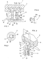
- the button 1 according to the invention comprises a main body of the button 2, a leg body 3, and a fastening body 4.
- the main body of the button 2 has a substratum 5 of a well-known form, for example, a discoidal shape, which is made up by machining natural materials such as metal, horn, glass, ceramic, and others, or by molding artifical materials such as acetal resin, acetate-polyester synthetic resin, acryl resin, urea resin, epoxy resin, ABS resin, and the like.
- the diameter D1 of the opening of the cavity 9 is formed within the range of 3 to 7mm, usually, for example, in about 4.6mm, the diameter D2 of the innermost face 7b within the range of 6 to 13mm, usually, for example, in about 8.6mm, and the dimension of the depth L1 in the range of 1.3 to 3mm, usually, for example, in about 2.0mm.
- the above-mentioned slanting surface 7a is also formed between itself and the under surface of the main body of the botton 2 through the interposition of a right-cylindrical slanting surface.
- the form of the cavity 9 is permissible to be modified in various ways, if it only is in posession of some slanting surface 7a widening toward the innermost part.
- the leg body 3 is a molded one being made of synthetic resins such as polyacetal resin, polycarbonate resin and the like, rich in toughness, elasticity, and creep proof.
- This leg body 3 is provided at the upper end of a circular and cylinder-shaped basal part 12 through which passes an inner hole 11 extending from the lower end and forming a square hole with a column-shaped inserting part 13 being larger in diameter than the above basal part 12 concentrically and continuously, while the basal part 12 is provided around the lower end part of its outer circumference with a flange 15.
- the inserting part 13 is provided concavely at the middle of its upper face with an allowance 16 consisting of a bottomed hole.
- the diameter D3 of this allowance 16 is set between 1.7mm and 4.0mm, usually, for example, on about 1.5mm.
- the diameter D1 of the insenting part 13 is made in the range of 3 to 7mm, for example, at about 4.7mm, and its length L3 is chosen from among 2.5 to 6mm, for example, about 4mm.
- the basal part 12 is provided with an elastic piece 22, resilient and bendable, which is fitted into a facing-sideways U-shaped split groove being formed in such a manner that its upper side passes along the boundary part with the above-" mentioned inserting part 13, that its flank is situated at the side edge of one side face lla of the inner hole 11, and that its lower end comes up to the upper surface of the above-mentioned flange 15.
- the meshing part 23 is provided in the multistage form with serrated convexes whose upper surfaces constitute nearly horizontal meshing faces 24a, and which have inclined surfaces 24c sloping inwardly throughvertically descending parts 24b of narrow breadth from the outer end parts of the above-mentioned meshing faces 24a.
- the welding by the rolling friction is performed in such a manner that after putting the inserting part 13 of the leg body 3 into the cavity 9, the leg body 3 is made to rotate at about 5,000 ⁇ 20,004rpm while applying the load of about 0.5 -5.0kg between the leg body 3 and the main body of the buttom 2, as a result of which there is generated the frictional heat between the inmost face 7b of the cavity 9 and the end part of the inserting part 13, thereby softening and melting the both.
- the inserting part 13 changes the shape of itself and goes to fill the cavity 9, whereby it becomes possible that the both, that is, the main body of the button 2 and the leg body 3 are bonded firmly and stably.
- the main body of the buttom 2 should be made using the materials having a small thermal deformation coefficient, for example, such as metal, ceramic, thermosetting resin, and the like, while for the leg body 3 there is to be adopted thermoplastic resins.
- the main body of the button 2 are used materials having the thermal deformation of a smaller variate than that of the leg body 3.
- the bonding operation mentioned above will be finished in about 2 -3 seconds.
- the above-mentioned fastening body 4 is provided protuberantly on the nearly central part of a base piece 27 with an axial rod 28.
- This axial rod 28 is a prism of an almost square section which is able to be inserted into the inner hole 11.
- the top end part of the axial rod 28 is formed into, for example, a square weight-shaped guide part 29.
- the engaging face 30a of the groove part 30 is formed a little longer than the engaging face 24a of the above-mentioned convex 24, and the four corners of the axial rod 28 is chamfered.
- the axial rod 28 is made integrally with the nearly elliptic base piece 27 by using the same material with the leg body 3.
- the axial rod 28 can make its pawling parts engage with the meshing parts 23 of the elastic piece 22 ; the top end part of the axial rod 28 is so designed as to be as long as being able to reach near the upper end part of the above-mentioned inner hole 11.
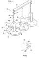
- a number of fastening bodies 4 can take the form of a magazine 43 of a plurality of fastening bodies standing in a row by attaching the pointed heads of the above-mentioned axial rods 28 to a single connecting piece 40 through the interposition of so many linking pieces 41.
- These linking pieces 41 each are provided at the upper parts of thread parts 45 of a small diameter with guiding pieces 46 protuberantly extending in the horizontal direction.
- the above-mentioned fastening body 4 pierces the cloth material C by using for example, such a tag machine 50 as shown in Figs. 7 (a) and (e).
- a tag machine 50 In the capacity of a tag machine 50, there is used, for example, a pistol- shaped one made and sold by KK. Japanese Bannok.
- the tag magazine 50 is provided with a needle body 52 along the underside of which a notched groove 51 is cut from end to end continuously, and with a piston 54 which shifts a pushing rod 53 through the interior of the above needle body 52. Further, near the rear end of the needle body 52, the tag machine 50 is provided with a groove part 56 which makes the above-mentioned magazine 43 insert in while making the guiding piece 46 of the magazine 43 being situated at the rear end part of the needle body 52.
- the axial rod 28 of the fastening body 4 which has pierced the cloth material C in such a manner is pushed into the inner hole 11 of the leg body 3 which is bonded in one with a main body of the button 2 while aligning the meshing part 23 with the pawling part 31.
- the main body of button 2 can be attached firmly to the cloth material C, thereby the basal part 12 of the leg body 3 becoming a substitute for the root-winding part.
- the above-mentioned pin bodies 32 are stuck in the cloth material C and thereby prevents the main body of button 2 from turning-round.
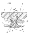
- Fig. 8 to 17 show another example of this invention.
- the main body of the button 2 and the leg body 3 are fixed on each other by the use of an adhesive agent A.
- the main body of the button 2 has a substratum 5 of a well-known form, for example, a discoidal shape, which is made up by machining natural materials such as metal, horn, glass, ceramic, and others, or by molding artifical materials such as acetal resin, acetate-polyester synthetic resin, acryl resin, urea resin, epoxy resin, ABS resin, and the like.
- the leg body 3 is a molded one being made of synthetic resins such as polyacetal resin, polycarbonate resin and the like, rich in toughness, elasticity, and creep proof.
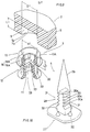
- This leg body 3 is provided at the upper end of a circular and cylinder-shaped basal part 12 through which passes an inner hole 11 extending from the lower end and forming a square hole with a column-shaped inserting part 13 being larger in diameter than the above basal part 12 concentrically and continuously, while the basal part 12 is provided round the respective outer circumferences of the upper and lower end parts of it with the flanges 14, 15, separately.
- the inserting part 13 is provided concavely at the middle of its upper face with an allowance 16.
- This allowance 16 consists of a square hollow part 16A being formed by the extension part of an inner hole 11, and a circular hollow part 16B being formed following the upper end of the above-mentioned square hollow part 16A ; and further the allowance 16 communicates concentrically with the above-mentioned inner hole 11.
- the inserting part 13 is provided at its upper end part with a tapered part 13A having an inclined face of an angle of about 45 * .
- the diameter dl of the insenting part 13 is equal to the diameter Dl of the cavity 9, the both being set, for example, at about 5mn.
- the basal part 12 is equipped with a pair of elastic pieces 22, 22 in such a manner as to be opposite to each other.
- the elastic piece 22 is resilient and bendable, and is fitted into a facing-sideways U-shaped split groove being formed in such a manner that its upper side passes along the lower end parts of the flanges 14, that its flank is situated at the side edge of one side face of the inner hole 11, and that its lower end comes up to the upper part of the above-mentioned flange 15.
- the meshing part 23 is provided in the multistage form with serrated convexes whose upper surfaces constitute nearly horizontal meshing faces 24a, and which have inclined surfaces 24c sloping inwardly through from the inner end parts of the above-mentioned meshing faces 24a.
- the adhesive agent A used in this example is an instantaneous one whose base is cyanoacrylate.
- this base will be apt to cause the whitening of the peripheral region of the adhesive part as a result of the evaporation and re-adhesion of the base for its own sake.
- a base of such a kind as of a low-whitening type there is used in this example a base of such a kind as of a low-whitening type.
- the adhesive agent A some additives containing both a boiling point-rising agent which hightens the boiling point and prevents the evaporation, and also a hardening agent which hastens the rate of polymerization.
- the adhesive agent A used in this example to surpress the evaporation and to prevent the whitening on the basis of the rising of the boiling point and the rapid hardening of itself, thereby being able to bond the main body of the button 2 and the leg body 3 with each other attractively in appearance.
- boiling point-rising agents alkyls belonging to the methyl series there are used as boiling point-rising agents alkyls belonging to the methyl series, and as hardening agents amines, polyamids, acids and the like, and further hydrous silica gel which absorbs evaporated gas generating form solvents, and others.
- the above-mentioned fastening body 4 is provided protuberantly on the nearly central part of a base piece 27 with an axial rod 28.
- This axial rod 28 is a prism of an almost square section which is able to be inserted into the inner hole 11.
- the top end part of the axial rod 28 is formed into a cone-shaped insert piece 29 having a pointed head through the interposition of a cut-off part 28A of a small breadth.
- the engaging face 30a of the groove part 30 is formed a little longer than the engaging face 24a of the above-mentioned-convex 24.
- the axial rod 28 is made integrally with the nearly elliptic base piece 27 and the insert piece 29 by using the same material with the leg body 3.
- the axial rod 28 can make its pawling parts engage with the meshing parts 23 of the elastic piece 22 ; the top end part of the axial rod 28 is so designed as to be as long as being able to reach near the above-mentioned extension part of an inner hole 11.
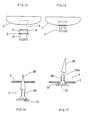
- the adhesive agent A is applied, as shown in Fig. 14, to the inserting part 13 or to the cavity 9, and then, as shown in Fig. 15, that inserting part 13 is inserted into the cavity 9. In this way, the above-mentioned main bady of the button 2 and the leg body 3 are firmly fixed on each other by dint of the hardening of the adhesive agent A.
- the inserting part 13 can be easily inserted into the cavity 9 in the presence of the tapered part 13A.
- This tapered part 13A can form an adhesive agent receiver, preventing the adhesive agent A from being bulged out.
- the diameter dl of the inserting part 13 is set equal to the diameter Dl of the cavity 9 so as to be inserted tightly into the latter, as a result of which the ricketiness is eliminated and the fitting precision is elevated, while the hardening of the adhesive agent A is accelerated and the adhesive strength is heightend.
- the flange 14 at the upper end of the basal part 12 serves for preventing the adhesive agent A from flowing out.
- the above-mentioned fastening body 4 can make the axial rod 28 pierce the cloth material C by stabbing the cloth material C with the insert piece 29, as shown in Fig. 16. After the axial rod 28 has finished the penetration, the insert piece 29 is cut and removed from the cut-off part 28A.
- the axial rod 28 of the fastening body 4 which has pierced through the cloth material C, as mentioned above, is pushed-into the inner hole 11 of the leg body 3 being bonded with the main body of the button 2 in a body while aligning the meshing part 23 with the pawling part 31.
- the fastening body 4 is provided with pawling part 31 not only at two side faces facing to each other but also even at one single side face or at four side faces; or it is possible for the inner hole 11 to adopt not only 'the square hole, but also various holes of such formes as a triangle, an ellipse, a pentagon, and other; or the number of elastic pieces-22.can be made to vary at will.
- the meshing part 23 and the pawling part 31 only are such ones as meshing each with other to prevent them from coming off, it is possible to adopt such convexes 24 or grooves 30 as having the forms of not only a sawtooth but also a facing-sideways U-shaped tooth, a triangular tooth, a circular arc-shaped tooth, and others.
- the button 1 according to the invention may be transformed into various embodiments, for example, now by making threading holes for decorationin the main body of the button 2 now by attaching ornamental knots to it.
- the button according to the invention is such a one which comprises the main body of the button, the leg body, and the fastening body.
- the fixing on each other can be speeded up to elevate the productivity, and also the fixing strength can be increased sharply up to the degrees of 5 ⁇ 25 kg to enhance the reliability in the fitted state of buttons.
Landscapes
- Mechanical Control Devices (AREA)
- Slide Fasteners, Snap Fasteners, And Hook Fasteners (AREA)
Applications Claiming Priority (4)
| Application Number | Priority Date | Filing Date | Title |
|---|---|---|---|
| JP59226438A JPS61103402A (ja) | 1984-10-27 | 1984-10-27 | ボタン |
| JP226438/84 | 1984-10-27 | ||
| JP235884/85 | 1985-10-21 | ||
| JP23588485A JPS6294101A (ja) | 1985-10-21 | 1985-10-21 | ボタン |
Publications (2)
| Publication Number | Publication Date |
|---|---|
| EP0180436A2 true EP0180436A2 (fr) | 1986-05-07 |
| EP0180436A3 EP0180436A3 (fr) | 1987-01-21 |
Family
ID=26527168
Family Applications (1)
| Application Number | Title | Priority Date | Filing Date |
|---|---|---|---|
| EP85307752A Withdrawn EP0180436A3 (fr) | 1984-10-27 | 1985-10-28 | Bouton |
Country Status (1)
| Country | Link |
|---|---|
| EP (1) | EP0180436A3 (fr) |
Cited By (6)
| Publication number | Priority date | Publication date | Assignee | Title |
|---|---|---|---|---|
| GB2232871A (en) * | 1989-06-14 | 1991-01-02 | Diane Bates | Buttons |
| GB2239160A (en) * | 1989-12-20 | 1991-06-26 | Ming Fu Hsiau | Button |
| FR2810213A1 (fr) * | 2000-06-19 | 2001-12-21 | Christophe Lenglet | Dispoisitif de fixation pour bouton amovible |
| CN102488362A (zh) * | 2011-12-02 | 2012-06-13 | 永嘉县迈利达钮扣研发中心有限公司 | 一种金属钮扣扣脚自动装配装置及装配方法 |
| IT202300003741A1 (it) * | 2023-03-02 | 2024-09-02 | Berning Italia S R L | Bottone per abbigliamento |
| EP4424200A1 (fr) * | 2023-03-02 | 2024-09-04 | Berning Italia S.R.L. | Bouton pour vêtement |
Family Cites Families (2)
| Publication number | Priority date | Publication date | Assignee | Title |
|---|---|---|---|---|
| SE389008B (sv) * | 1975-08-29 | 1976-10-25 | S A J Liljendahl | Knapp |
| US4541148A (en) * | 1983-02-14 | 1985-09-17 | Nippon Notion Kogyo Co., Ltd. | Tiltable tack button |
-
1985
- 1985-10-28 EP EP85307752A patent/EP0180436A3/fr not_active Withdrawn
Cited By (7)
| Publication number | Priority date | Publication date | Assignee | Title |
|---|---|---|---|---|
| GB2232871A (en) * | 1989-06-14 | 1991-01-02 | Diane Bates | Buttons |
| GB2239160A (en) * | 1989-12-20 | 1991-06-26 | Ming Fu Hsiau | Button |
| FR2810213A1 (fr) * | 2000-06-19 | 2001-12-21 | Christophe Lenglet | Dispoisitif de fixation pour bouton amovible |
| CN102488362A (zh) * | 2011-12-02 | 2012-06-13 | 永嘉县迈利达钮扣研发中心有限公司 | 一种金属钮扣扣脚自动装配装置及装配方法 |
| CN102488362B (zh) * | 2011-12-02 | 2014-04-16 | 永嘉县迈利达钮扣研发中心有限公司 | 一种金属钮扣扣脚自动装配装置及装配方法 |
| IT202300003741A1 (it) * | 2023-03-02 | 2024-09-02 | Berning Italia S R L | Bottone per abbigliamento |
| EP4424200A1 (fr) * | 2023-03-02 | 2024-09-04 | Berning Italia S.R.L. | Bouton pour vêtement |
Also Published As
| Publication number | Publication date |
|---|---|
| EP0180436A3 (fr) | 1987-01-21 |
Similar Documents
| Publication | Publication Date | Title |
|---|---|---|
| USRE27391E (en) | Connector for holding articles together | |
| US4402641A (en) | Self centering fastener | |
| KR200181169Y1 (ko) | 상호 결합식 파스너 부재 | |
| EP0180436A2 (fr) | Bouton | |
| US3516124A (en) | Connector for holding articles together | |
| US2769443A (en) | Hypodermic devices | |
| CN113217514A (zh) | 固定组件的扣件结构、固定组件及固定组件的组接方法 | |
| KR20030082446A (ko) | 스냅 파스너가 달린 테이프 | |
| CN205446322U (zh) | 固定组件的扣件结构及固定组件 | |
| EP0123215B1 (fr) | Bouton | |
| KR20010062596A (ko) | 버튼용 택 | |
| US4970766A (en) | Button attachable to clothes without using thread | |
| FI98977C (fi) | Liukukappale vetoketjua varten ja sen valmistusmenetelmä | |
| US7137766B2 (en) | Screw and plastic part unit | |
| US2920325A (en) | Fastener setting tools | |
| US3448464A (en) | Attachment of plastic fasteners to fabric articles | |
| US3475794A (en) | Stud mounted moulding fastener | |
| US835725A (en) | Broom-holder. | |
| US4265160A (en) | Composite staple-type fastener having relatively movable locking portions | |
| US2520781A (en) | Button structure | |
| KR910008612B1 (ko) | 수지 제품 | |
| JPS6294101A (ja) | ボタン | |
| US4190304A (en) | Apparatus for use in the construction and decoration of upholstered furniture and the like | |
| US2649633A (en) | Machine attached button | |
| JP2554018B2 (ja) | 靴のヒール |
Legal Events
| Date | Code | Title | Description |
|---|---|---|---|
| PUAI | Public reference made under article 153(3) epc to a published international application that has entered the european phase |
Free format text: ORIGINAL CODE: 0009012 |
|
| AK | Designated contracting states |
Kind code of ref document: A2 Designated state(s): DE FR GB IT |
|
| PUAL | Search report despatched |
Free format text: ORIGINAL CODE: 0009013 |
|
| AK | Designated contracting states |
Kind code of ref document: A3 Designated state(s): DE FR GB IT |
|
| STAA | Information on the status of an ep patent application or granted ep patent |
Free format text: STATUS: THE APPLICATION IS DEEMED TO BE WITHDRAWN |
|
| 18D | Application deemed to be withdrawn |
Effective date: 19870723 |
|
| RIN1 | Information on inventor provided before grant (corrected) |
Inventor name: IWASA, MASATSUGU |