EP4424200A1 - Bouton pour vêtement - Google Patents
Bouton pour vêtement Download PDFInfo
- Publication number
- EP4424200A1 EP4424200A1 EP24160474.3A EP24160474A EP4424200A1 EP 4424200 A1 EP4424200 A1 EP 4424200A1 EP 24160474 A EP24160474 A EP 24160474A EP 4424200 A1 EP4424200 A1 EP 4424200A1
- Authority
- EP
- European Patent Office
- Prior art keywords
- tack
- button
- shaft
- coupling element
- faces
- Prior art date
- Legal status (The legal status is an assumption and is not a legal conclusion. Google has not performed a legal analysis and makes no representation as to the accuracy of the status listed.)
- Withdrawn
Links
Images




Classifications
-
- A—HUMAN NECESSITIES
- A44—HABERDASHERY; JEWELLERY
- A44B—BUTTONS, PINS, BUCKLES, SLIDE FASTENERS, OR THE LIKE
- A44B1/00—Buttons
- A44B1/18—Buttons adapted for special ways of fastening
- A44B1/28—Buttons adapted for special ways of fastening with shank and counterpiece
- A44B1/32—Shank inserted into counterpiece and locked by sliding or rotating
Definitions
- the present invention relates to a button for clothing.
- the invention can be used in the textile industry for manufacturing items of clothing.
- press-studs are widely used that are made of metal and/or plastic material, and are used in particular on garments made of denim, such as jeans, jackets or shirts.
- Automatic buttons are made up of two complementary elements arranged on two separate flaps of the item of clothing, and can be coupled and decoupled elastically.
- buttons In these buttons, the pressure is exerted between the two complementary elements.
- Tack buttons usually have:
- the shaft of the tack is press-fitted into the tubular shank of the mushroom-shaped component, after having been passed through the flap.
- the shaft of the tack/rivet and the shank of the mushroom-shaped component have such shapes and dimensions as to produce a mutual interference after the former is inserted into the latter, generating a stable and non-removable coupling.
- press-studs which have, instead of a tack/rivet, a screw with a threaded shaft which is inserted by pressure, or by screwing, into the shank of the mushroom-shaped component, and can be removed from it by unscrewing it from the mushroom-shaped component.
- buttons Furthermore, with such a button the operation to remove the buttons is long and inconvenient, especially when it is necessary to remove more than one button.
- the aim of the present invention is to provide a button for clothing which is capable of improving the prior art in one or more of the above-mentioned aspects.
- an object of the invention is to provide a button for clothing that can be removed from the item of clothing to which it is applied without the aid of tools.
- Another object of the invention is to provide a button for clothing that can be removed from the item of clothing to which it is applied more easily and rapidly than similar, conventional buttons.
- a further object of the invention is to provide a button for clothing that can be completely and easily recycled.
- Another object of the present invention is to overcome the drawbacks of the prior art in a different manner to any existing solutions.
- Another object of the invention is to provide a button for clothing that is highly reliable, easy to implement and at low cost.
- a button for clothing which comprises:
- a button for clothing is generally designated by the reference number 10.
- the button 10 comprises:
- One of the peculiarities of the invention consists in that it comprises manually removable means for associating the tack 12 with the mushroom-shaped component 11.
- the expression "manually removable” means that the tack 12 can be removed from the mushroom-shaped component 11 without the aid of tools.
- the button 10 is a press-button of the "tack" type.
- the button 10 is associated with a flap L of an item of clothing.
- the tack 12 has a head 13 and a shaft 14.
- the head 13 has two opposing straight edges 15a, 15b.
- One of the peculiarities of the tack 12 consists in that the shaft 14 has:
- longitudinal faces means faces that extend in the longitudinal direction, i.e. the direction of extension of the tack.
- the expression “at least partially flat” means that the first longitudinal faces 16a, 16b, are flat for at least one longitudinal portion thereof.
- Each one of the two second longitudinal faces 17a, 17b, is interposed between the two first longitudinal faces 16a, 16b.
- the third face 17a and the fourth face 17b have a plurality of teeth 18a, 18b, with a transverse edge 19 that is at least partially rounded.
- transverse edge means the edge lying on a transverse plane, i.e. at right angles to the longitudinal direction and substantially at right angles to the two first longitudinal faces 16a, 16b.
- this transverse edge 19 has an at least partially curvilinear profile along its plane of arrangement.
- the teeth 18a of the third face 17a correspond to the teeth 18b of the fourth face 17b.
- the mushroom-shaped component 11 comprises, in the following order:
- the tack 12 is adapted to be inserted in the mushroom-shaped component 11, by pushing the tip 20 and the shaft 14 inside the cap holder element 23 and the coupling element 22.
- such means for associating the tack 12 with the mushroom-shaped component 11 comprise the shaft 14 of the tack 12 and the coupling element 22 of the tack 12.
- the cap holder element 23 has:
- the second portion 25 has, at the free end, an inlet 26 for inserting the tack 12.
- This inlet 26 is constituted by a tubular third portion 27, which is coaxial to the tubular second portion 25 and inside the latter.
- the outside diameter of the third portion 27 is smaller than the inside diameter of the second portion 25.
- the third portion 27 is adapted to guide the tack 12 toward the coupling element 22 while keeping it in axial alignment.
- the coupling element 22 of the tack 12 is inserted into the cap holder element 23 and is closed inside the latter by the cap 21.
- the coupling element 22 substantially replicates the internal contouring of the cap holder element 23 and has:
- the coupling element 22 is provided, at the free end of the fifth portion 29, with a hole 30 for inserting and fastening the tack 12.
- This hole 30 has a substantially rectangular shape, replicating the transverse profile of the shaft 14 of the tack 12, at the transverse edges 19 of two corresponding teeth 18a, 18b, respectively of the third face 17a and of the fourth face 17b.
- the hole 30 has:
- the mutual distance between the first edges 31a and 31b of the hole 30 is:
- the minimum distance between corresponding points of the second longitudinal faces 17a, 17b is the minimum distance between a point P1 of the interface region between one tooth 18a of the third face 17a and the next tooth 18a, and the corresponding point P2 of the interface region between one tooth 18b of the fourth face 17b and the next tooth 18b.
- the maximum distance between corresponding points of the second longitudinal faces 17a, 17b is the maximum distance between a point P3 on the transverse edge 19 of a tooth 18a of the third face 17a and the corresponding point P4 on the transverse edge 19 of a tooth 18b of the fourth face 17b.
- the hole 30 is substantially defined by the convergence of four slats 35a, 35b, 36a, 36b, which extend at the free end of the fifth portion 29 of the coupling element 22, toward the inside and in a single piece with the fifth portion 29.
- Such slats 35a, 35b, 36a, 36b have a substantially trapezoidal shape with the major base proximate to/at the free end of the fifth portion 29 and the minor base directed toward the cap 21.
- each one of the first edges 31a, 31b of the hole 30 substantially corresponds to the minor base of a respective first lamina 35a, 35b
- each one of the second edges 32a, 32b of the hole 30 substantially corresponds to the minor base of a respective second lamina 36a, 36b.
- the first slats 35a, 35b are under tension as a consequence of the deformation produced by the insertion of the tack 12 into the coupling element 22.
- the button 10 comprises rotation-preventing/retention means between the coupling element 22 and the cap holder element 23.
- rotation-preventing/retention means are constituted by:
- the rotation-preventing/retention means between the coupling element 22 and the cap holder element 23 can be implemented differently, for example by means of one or more prominences or protuberances on the first portion 24 of the cap holder element 23 and corresponding and complementarily-shaped indentations on the fourth portion 28 of the coupling element 22.
- the straight edges 15a and 15b of the head 13 of the tack 12 and the first flat faces 33a, 33b of the fifth portion 29 and/or the second flat faces 40a, 40b of the second portion 25 are also adapted to facilitate the orientation of the tack 12 with respect to the coupling element 22 while applying the button 10 to the flap L, and to orient the tack 12 with respect to the coupling element 22 while removing the former from the latter.
- the straight edges 15a, 15b are parallel to the first longitudinal faces 16a, 16b of the shaft 14 of the tack 12
- the first flat faces 33a, 33b of the fifth portion 29 are parallel to the first edges 31a and 31b of the hole 30
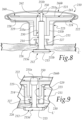
- in order to fix the tack 12 to the coupling element 22 it is necessary to orient the straight edges 15a, 15b at right angles to the first flat faces 33a, 33b, as shown in Figure 6a .
- the straight edges of the head of the tack and the first flat faces of the coupling element of the tack can be arranged differently, and the tack and, as a consequence, the coupling element are oriented during the step of fixing the button to the item of clothing.
- Fixing of the tack 12 to the mushroom-shaped component 11 is done by using pressure to insert the shaft 14 of the tack 12 into the cap holder element 23, and simultaneously into the coupling element 22, after having suitably oriented the head 13 and therefore the shaft 14 with respect to the fourth portion 28 of the coupling element 22 using the straight edges 15a, 15b and the first flat faces 33a, 33b, as explained above.
- the button 10 is made entirely of metallic material such as stainless steel and/or plastic material such as nylon/polyamide.
- FIG. 7 shows another embodiment of the tack, generally designated by the reference number 112.
- the tack 112 has a head 113 and a shaft 114.
- One of the peculiarities of the tack 112 consists in that the shaft 114 has:
- transverse cross-section means the cross-section lying on a transverse plane, i.e. at right angles to the longitudinal direction and substantially at right angles to the two first longitudinal faces 116a, 116b.
- the use of the tack 112 is similar to the use of the tack 12 explained previously in the first embodiment.
- the mutual distance between the first edges 31a and 31b of the hole 30 is:
- the means for associating the tack 12, 112 with the mushroom-shaped component 11 comprise the shaft 14, 114 of the tack 12, 112 and the coupling element 22 of the tack 12, 112.
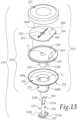
- a button for clothing in a third embodiment thereof, is generally designated by the reference number 210.
- the button 210 comprises:
- the button 210 is a press-button of the "tack" type.
- the button 210 is associated with a flap L' of an item of clothing.
- the tack 212 has a head 213 and a shaft 214.
- the head 213 has two opposing straight edges 215a, 215b.
- the shaft 214 has a widened and flattened end tip 250, with two opposing faces 251a, 251b which are at least partially flat, each one extending on a plane parallel to the plane of arrangement of a respective straight edge 215a, 215b of the head 213.
- the faces 251a, 251b of the tip 250 have a size, in the direction at right angles to the direction of extension of the shaft 214, that is greater than that of the shaft 214 and/or of its diameter.
- the tip of the tack is flattened and has a size, in the direction at right angles to the direction of extension of the shaft, that corresponds to that of the shaft and/or of its diameter.
- the mushroom-shaped component 211 comprises, in the following order:
- the tack 212 is adapted to be inserted in the mushroom-shaped component 211, by pushing the tip 250 and the shaft 214 inside the cap holder element 223 and the coupling element 222.
- such means for associating the tack 212 with the mushroom-shaped component 211 comprise the shaft 214 and the tip 250 of the tack 212 and the coupling element 222 of the tack 212.
- the cap holder element 223 has:
- the second portion 225 has, at the free end, an inlet 226 for inserting the tack 212.
- This inlet 226 is constituted by a tubular third portion 227, which is coaxial to the tubular second portion 225 and inside the latter.
- the outside diameter of the third portion 227 is smaller than the inside diameter of the second portion 225.
- the third portion 227 is adapted to guide the tack 212 toward the coupling element 222 while keeping it in axial alignment.
- the coupling element 222 of the tack 212 is inserted into the cap holder element 223 and is closed inside the latter by the cap 221.
- the coupling element 222 substantially replicates the internal contouring of the cap holder element 223 and has:
- the coupling element 222 is provided, at the free end of the fifth portion 229, with a hole 230 for inserting the tack 212.
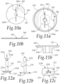
- This coupling element 222 has a lamina 260 for the abutment/interlocking of the tip 250 of the tack 212, which has a slit 261 passing through its thickness, and is provided with a widened central portion 262.
- the widened central portion 262 has a circular profile with:
- the slit 261 is defined by two opposing flaps 266a, 266b, which are arranged, at least proximate to the central portion 262, at a mutual distance at least slightly greater than the distance between the faces 251a, 251b of the tip 250 of the tack 212.
- the lamina 260 is separated from the fourth portion 228 and is inserted into a seat 263 of the fourth portion 228, arranged on the face of the fourth element 228 located opposite to the face from which the fifth portion 229 extends.
- the lamina 260 is in a single piece with the fourth portion 228.
- the lamina 260 has an at least partially circular profile with a straight section 264 adapted to come into abutment against a straight edge 265 of the seat 263 of the fourth portion 228, in order to prevent the rotation of the lamina 260.
- the button 210 comprises rotation-preventing/retention means between the coupling element 222 and the cap holder element 223.
- rotation-preventing/retention means are constituted by:
- the rotation-preventing/retention means between the coupling element 222 and the cap holder element 223 can be implemented differently, for example by means of one or more prominences or protuberances on the first portion 224 of the cap holder element 223 and corresponding and complementarily-shaped indentations on the fourth portion 228 of the coupling element 222.
- the straight edges 215a and 215b of the head 213 of the tack 212 and the first flat faces 233a, 233b of the fifth portion 229 and/or the second flat faces 240a, 240b of the second portion 225 are also adapted to facilitate the orientation of the tack 212 with respect to the coupling element 222, in the step of applying the button 210 to the flap L', and to orient the tack 212 with respect to the coupling element 222 in the step of removing the former from the latter.
- the straight edges 215a, 215b of the head 213 of the tack 212 are parallel to the faces 251a, 251b of the tip 250 of the tack 212, and the first flat faces 233a, 233b of the fifth portion 229 are parallel to the flaps 266a, 266b that define the slit 261, then in order to fix the tack 212 to the coupling element 222 it is necessary to orient the straight edges 215a, 215b at right angles to the first flat faces 233a, 233b.
- the straight edges of the head of the tack and the faces of the tip of the tack can be arranged differently, and the tack and, as a consequence, the coupling element are oriented during the step of fixing the button to the item of clothing.
- Fixing of the tack 212 to the mushroom-shaped component 211 is done by using pressure to insert the shaft 214 of the tack 212 into the cap holder element 223, and simultaneously into the coupling element 222, after having suitably oriented the head 213 and therefore the shaft 214 of the tack 212 with respect to the fourth portion 228 of the coupling element 222 using the straight edges 215a, 215b and the first flat faces 233a, 233b, as explained above.
- the tack 212 can be easily pulled out from the mushroom-shaped component 211, in so doing removing the button 210 from the item of clothing.
- Figure 14 is a cross-sectional side view of a button according to the invention in a fourth embodiment.
- the button for clothing according to the invention is generally designated by the reference number 310 and all the components that are analogous to those of the third embodiment have been given the same reference numbers, increased by 100.
- the mushroom-shaped component 311 comprises in the following order:
- buttons 310 are simpler in terms of construction and more straightforward to manufacture.
- the tack 312 is adapted to be inserted in the mushroom-shaped component 311, by pushing the tip 350 and the shaft 314 directly inside the coupling element 322.
- the fixing of the tack 312 to the mushroom-shaped component 311 is done by using pressure to insert the shaft 314 of the tack 312 into the coupling element 322, after having suitably oriented the head 313 and therefore the shaft 314 of the tack 312 with respect to the fourth portion 328 of the coupling element 322 using the straight edges 315a, 315b and the first flat faces 333a, 333b of the fifth portion 329.
- the tack 312 can be easily pulled out from the mushroom-shaped component 311, in so doing removing the button 310 from the item of clothing.
- the button 210, 310 is made entirely of metallic material such as for example stainless steel and/or plastic material such as nylon/polyamide.
- the means for associating the tack 212, 312 with the mushroom-shaped component 211, 311 comprise the tip 250, 350 of the tack 212, 312 and the coupling element 222, 322 of the tack 212, 312.
- straight edges 15a, 15b, 215a, 215b, 315a, 315b of the head 13, 113, 213, 313 of the tack 12, 112, 212, 312 allow the removal of the tack 12, 112, 212, 312 from the mushroom-shaped component 11, 211, 311 manually, and without the need to use tools.
- the invention fully achieves the intended aim and objects by providing a button for clothing that can be removed from the item of clothing to which it is applied without the aid of tools.
- buttons for clothing have been devised that can be removed from the item of clothing to which it is applied more easily and rapidly than similar, conventional buttons.
- a button for clothing has been provided that can be completely and easily recycled.
Landscapes
- Details Of Garments (AREA)
Applications Claiming Priority (2)
| Application Number | Priority Date | Filing Date | Title |
|---|---|---|---|
| IT102023000003741A IT202300003741A1 (it) | 2023-03-02 | 2023-03-02 | Bottone per abbigliamento |
| IT202400001353 | 2024-01-25 |
Publications (1)
| Publication Number | Publication Date |
|---|---|
| EP4424200A1 true EP4424200A1 (fr) | 2024-09-04 |
Family
ID=90059732
Family Applications (1)
| Application Number | Title | Priority Date | Filing Date |
|---|---|---|---|
| EP24160474.3A Withdrawn EP4424200A1 (fr) | 2023-03-02 | 2024-02-29 | Bouton pour vêtement |
Country Status (1)
| Country | Link |
|---|---|
| EP (1) | EP4424200A1 (fr) |
Citations (6)
| Publication number | Priority date | Publication date | Assignee | Title |
|---|---|---|---|---|
| FR518828A (fr) * | 1918-12-07 | 1921-05-31 | Atlas Maschb G M B H | Bouton détachable |
| DE555264C (de) * | 1929-01-02 | 1932-07-20 | Adolf Kadletz | Loesbare Befestigungsvorrichtung fuer Knoepfe |
| EP0180436A2 (fr) * | 1984-10-27 | 1986-05-07 | Iwasa Sewing Co. Ltd. | Bouton |
| TWM344761U (en) * | 2008-06-13 | 2008-11-21 | mei-cen Guo | Improved attaching and positioning structure for covered button |
| WO2022234510A1 (fr) * | 2021-05-05 | 2022-11-10 | Spring ’85 S.p.A. | Bouton amovible |
| IT202300003741A1 (it) | 2023-03-02 | 2024-09-02 | Berning Italia S R L | Bottone per abbigliamento |
-
2024
- 2024-02-29 EP EP24160474.3A patent/EP4424200A1/fr not_active Withdrawn
Patent Citations (6)
| Publication number | Priority date | Publication date | Assignee | Title |
|---|---|---|---|---|
| FR518828A (fr) * | 1918-12-07 | 1921-05-31 | Atlas Maschb G M B H | Bouton détachable |
| DE555264C (de) * | 1929-01-02 | 1932-07-20 | Adolf Kadletz | Loesbare Befestigungsvorrichtung fuer Knoepfe |
| EP0180436A2 (fr) * | 1984-10-27 | 1986-05-07 | Iwasa Sewing Co. Ltd. | Bouton |
| TWM344761U (en) * | 2008-06-13 | 2008-11-21 | mei-cen Guo | Improved attaching and positioning structure for covered button |
| WO2022234510A1 (fr) * | 2021-05-05 | 2022-11-10 | Spring ’85 S.p.A. | Bouton amovible |
| IT202300003741A1 (it) | 2023-03-02 | 2024-09-02 | Berning Italia S R L | Bottone per abbigliamento |
Similar Documents
| Publication | Publication Date | Title |
|---|---|---|
| EP0695517B1 (fr) | Bouton pour l'habillement | |
| EP1519662B1 (fr) | Bouton-pression utilise avec des tissus | |
| US11805862B2 (en) | Button assembled with removable screw and method of attaching removable screw | |
| US2718640A (en) | Garment appendages | |
| EP4424200A1 (fr) | Bouton pour vêtement | |
| US2134037A (en) | Fastener | |
| EP1557107B1 (fr) | Bouton | |
| US20030140393A1 (en) | Knitted shirt collar with plastic stays | |
| US20050188510A1 (en) | Button affixable by hand pressure | |
| EP4346494B1 (fr) | Bouton amovible | |
| IT202300003741A1 (it) | Bottone per abbigliamento | |
| US2128640A (en) | Fastener attaching means | |
| US20070193487A1 (en) | Embossed Tufting Needle | |
| JPH0518481U (ja) | ミシン針 | |
| US2071575A (en) | Spring fastener | |
| US2574436A (en) | Closed type burr | |
| US2939191A (en) | Button | |
| CA3204754A1 (fr) | Ciseaux pour decoupe pres de coutures | |
| US20260115944A1 (en) | Scissors for cutting next to a seam | |
| CN208080665U (zh) | 一种可防止面壳变形的按扣 | |
| US245908A (en) | Button | |
| US20240381948A1 (en) | Socks With Fasteners | |
| JP7630168B2 (ja) | 保持用部材及びこれを用いたスナップファスナー | |
| US1760835A (en) | Tack-attached button | |
| US484792A (en) | Glove and garment fastener |
Legal Events
| Date | Code | Title | Description |
|---|---|---|---|
| PUAI | Public reference made under article 153(3) epc to a published international application that has entered the european phase |
Free format text: ORIGINAL CODE: 0009012 |
|
| STAA | Information on the status of an ep patent application or granted ep patent |
Free format text: STATUS: THE APPLICATION HAS BEEN PUBLISHED |
|
| AK | Designated contracting states |
Kind code of ref document: A1 Designated state(s): AL AT BE BG CH CY CZ DE DK EE ES FI FR GB GR HR HU IE IS IT LI LT LU LV MC ME MK MT NL NO PL PT RO RS SE SI SK SM TR |
|
| STAA | Information on the status of an ep patent application or granted ep patent |
Free format text: STATUS: THE APPLICATION IS DEEMED TO BE WITHDRAWN |
|
| 18D | Application deemed to be withdrawn |
Effective date: 20250305 |