EP0180504B1 - Dichtungsventil für pneumatische oder hydraulische Anlage - Google Patents
Dichtungsventil für pneumatische oder hydraulische Anlage Download PDFInfo
- Publication number
- EP0180504B1 EP0180504B1 EP85401983A EP85401983A EP0180504B1 EP 0180504 B1 EP0180504 B1 EP 0180504B1 EP 85401983 A EP85401983 A EP 85401983A EP 85401983 A EP85401983 A EP 85401983A EP 0180504 B1 EP0180504 B1 EP 0180504B1
- Authority
- EP
- European Patent Office
- Prior art keywords
- rod
- bore
- joint
- valve
- diameter
- Prior art date
- Legal status (The legal status is an assumption and is not a legal conclusion. Google has not performed a legal analysis and makes no representation as to the accuracy of the status listed.)
- Expired
Links
Images

Classifications
-
- F—MECHANICAL ENGINEERING; LIGHTING; HEATING; WEAPONS; BLASTING
- F16—ENGINEERING ELEMENTS AND UNITS; GENERAL MEASURES FOR PRODUCING AND MAINTAINING EFFECTIVE FUNCTIONING OF MACHINES OR INSTALLATIONS; THERMAL INSULATION IN GENERAL
- F16K—VALVES; TAPS; COCKS; ACTUATING-FLOATS; DEVICES FOR VENTING OR AERATING
- F16K1/00—Lift valves or globe valves, i.e. cut-off apparatus with closure members having at least a component of their opening and closing motion perpendicular to the closing faces
- F16K1/32—Details
- F16K1/34—Cutting-off parts, e.g. valve members, seats
- F16K1/36—Valve members
-
- F—MECHANICAL ENGINEERING; LIGHTING; HEATING; WEAPONS; BLASTING
- F41—WEAPONS
- F41B—WEAPONS FOR PROJECTING MISSILES WITHOUT USE OF EXPLOSIVE OR COMBUSTIBLE PROPELLANT CHARGE; WEAPONS NOT OTHERWISE PROVIDED FOR
- F41B11/00—Compressed-gas guns, e.g. air guns; Steam guns
- F41B11/70—Details not provided for in F41B11/50 or F41B11/60
- F41B11/72—Valves; Arrangement of valves
- F41B11/723—Valves; Arrangement of valves for controlling gas pressure for firing the projectile only
Definitions
- the technical sector of the present invention is that of sealing valves making it possible to release or prevent the passage of a compressed fluid in a pneumatic or hydraulic circuit.
- valves made up of a body, a one-piece rod and a seal. .
- the rod is subjected to the axial action of a means of translation and the body to the opposing actions of an elastic return means or of the fluid under pressure.
- patent FR-A-1 113 966 describes a sealing valve applied to a compressed air weapon, provided with a seal placed on the rod and compressed between a stop and the valve body.
- the disadvantage of this kind of device lies in the fact that the seal is movable both relative to the stop and relative to the body, which causes its premature wear.
- replacing this seal requires complete disassembly of the valve support assembly since the valve body and stem are inseparable.
- Patent FR-A-1,203,207 describes according to the preamble of claim 1 a sealing valve for a pneumatic or hydraulic circuit, movable inside a fluid intake cylinder.
- This valve comprises a body receiving in a axial bore a rod, a seal being interposed between the rod and the body.
- no details are provided on the mounting of this seal in a bore of the body.
- the object of the present invention is to provide a valve in which the compressive forces applied to the seal are reduced.
- the invention therefore relates to a sealing valve for a pneumatic or hydraulic circuit movable inside a fluid intake cylinder, of the type comprising a body provided with an axial bore receiving a rod, a seal being interposed between the rod and the body in a bore to cooperate with a stop of the intake cylinder, characterized in that the seal is compressed for mounting in a conical bore both axially and radially, the axial compression being carried out at using the shoulder of the rod and a convex annular bulge formed in the bottom of the bore, and the radial compression being obtained by the difference in diameter between on the one hand the internal diameter of the bore and the diameter external of the joint and on the other hand between the internal diameter of the bore of the joint and the diameter of the rear part of the rod.
- the longitudinal compression of the joint can be carried out when the rear part of the rod is in abutment on the shoulder.
- the valve is movable between two stops, the body applying to a first stop after the impact of a striker and the seal s 'applying back to a second stop to ensure sealing by the action of gas pressure.
- the valve body can be subjected to the pressure of gas from a reserve through a chamber.
- An advantage of the present invention lies in the fact that the life of the seal is extended, since the latter is not subjected to any stress during the impact of the striker; it avoids frequent dismantling of the weapon to replace this seal, which is incompatible with intensive use on a shooting range.
- Another advantage of the present invention lies in the fact that the position of the rod is fixed relative to the body, regardless of the force of percussion on the rod. This position is invariable over time and it follows that the free end of the rod is always located at an invariable distance from the valve seat. The reliability of the weapon and its performance are therefore preserved whatever the use of the weapon.
- Another advantage lies in the absence of crimping of the seal since it is subjected to radial and axial compression in its housing.
- Yet another advantage lies in the interchangeability of the components of the valve.
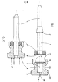
- a rod 1 having a shoulder 2 and a cylindrical rear part 3.
- the body 4 is provided with two cylindrical surfaces 5 and 6 separated by an annular rib 4a.
- the cylindrical surface 5 comprises openings 5a intended for the passage of the compressed fluid.
- the diameter of the bearing surface 5 corresponds to the internal diameter of the housing in which the valve is mounted so that this valve is mobile under the action of the compressed fluid acting on the valve body.
- the bearing surface 5 is preferably of a diameter greater than that of the bearing surface 6.
- the body 4 comprises a first conical bore 7 extended by a second cylindrical bore 8 and with a flat bottom 8a and possibly by a third 8b.
- the diameter of the bore 8 is provided so as to maintain and block the part 3 of the rod, in order to obtain a joining of the body and the rod by simple diametrical tightening.
- Bore 7 has a bottom provided with a convex annular bulge 7a and receives an annular seal 9 comprising an axial bore 10.
- the external diameter of the seal 9 is slightly greater than that of the bore 7 so as to cause radial compression of the seal when it is put in place.
- the diameter of the bore 10 of the joint is slightly less than the diameter of the rear part 3 of the rod, which makes it possible to obtain another radial compression of the joint by the rod.
- the body 4 can be made of brass and the rod 1 of treated steel.
- the seal 9 can be produced for example from an elastomer or any other material of similar characteristics.
- the rod 1, the gasket 9 and the body 4 have been brought together to form the valve.
- the seal is first placed in the bore 7 and then the rod is introduced.
- the rear part 3 of the rod is stuck on the flat bottom 8a and the shoulder 2 achieves a slight axial compression of the seal 9.
- the rod 1 can be separated from the body 4 since there is no crimping of the seal on the body, which avoids the complete replacement of the valve.
- the seal 9 is intended to absorb the shocks in abutment of the valve generated by the gas pressure exerted along the arrow F on the body 4.
- the axial and radial compression of the seal causes a slight bulging of the free surface of it.
- the diametrical tightening and the axial compression of the seal 9 between the body 4 and the rod 1 make it possible to control the radial and axial swelling of the seal.
- the apparatus comprises in particular a housing 11, for example at its upper part, enclosing a chamber 12 in communication with a reserve 17 of compressed gas, closed by the valve body.
- the valve body is movable between the stops 13 and 14, the spacing of which delimits the stroke of the valve.
- the stop 14 constitutes the valve seat.
- the rod 1 is subjected to the action of a striker 15 actuated in a known manner during the firing sequence.
- the housing 11 includes a conduit 16 for directing the compressed gas into a barrel (not shown) for launching the projectiles.
- the end of the rod 1 is located at a fixed distance s from the housing 11.
- the operation is as follows: when the rod is actuated by the striker 15, the body 4 quickly comes into contact with the stop 13, which causes the gas to flow through the openings 5a of the bearing surface 5, the momentarily free passage between the bearing surface 6 and the stop 14 and the conduit 16.
- the impact of the body 4 against the stop 13 causes the opening movement of the valve to stop and a reversal of direction, which with the help of the fluid pressure causes closing the valve by applying the seal 9 to the stop 14 or valve seat.
- the return shock is therefore absorbed, which ensures rapid sealing, therefore a gas consumption limited to the quantity necessary to ensure the desired propulsion of the projectile.
Landscapes
- Engineering & Computer Science (AREA)
- General Engineering & Computer Science (AREA)
- Mechanical Engineering (AREA)
- Lift Valve (AREA)
- Fluid-Pressure Circuits (AREA)
- Actuator (AREA)
Claims (4)
Priority Applications (1)
| Application Number | Priority Date | Filing Date | Title |
|---|---|---|---|
| AT85401983T ATE39182T1 (de) | 1984-10-11 | 1985-10-11 | Dichtungsventil fuer pneumatische oder hydraulische anlage. |
Applications Claiming Priority (2)
| Application Number | Priority Date | Filing Date | Title |
|---|---|---|---|
| FR8415580 | 1984-10-11 | ||
| FR8415580A FR2571808B1 (fr) | 1984-10-11 | 1984-10-11 | Valve d'etancheite pour circuit pneumatique ou hydraulique |
Publications (2)
| Publication Number | Publication Date |
|---|---|
| EP0180504A1 EP0180504A1 (de) | 1986-05-07 |
| EP0180504B1 true EP0180504B1 (de) | 1988-12-07 |
Family
ID=9308547
Family Applications (1)
| Application Number | Title | Priority Date | Filing Date |
|---|---|---|---|
| EP85401983A Expired EP0180504B1 (de) | 1984-10-11 | 1985-10-11 | Dichtungsventil für pneumatische oder hydraulische Anlage |
Country Status (4)
| Country | Link |
|---|---|
| EP (1) | EP0180504B1 (de) |
| AT (1) | ATE39182T1 (de) |
| DE (1) | DE3566727D1 (de) |
| FR (1) | FR2571808B1 (de) |
Family Cites Families (6)
| Publication number | Priority date | Publication date | Assignee | Title |
|---|---|---|---|---|
| FR1113966A (fr) * | 1954-11-05 | 1956-04-06 | Fusil, revolver ou arme analogue à air comprimé | |
| FR1203207A (fr) * | 1958-07-25 | 1960-01-15 | Mitraillette à air comprimé | |
| CH377685A (de) * | 1959-12-31 | 1964-05-15 | Bertschinger Jacques | Mit Druckgas betriebene Schiessvorrichtung |
| US3527194A (en) * | 1967-03-20 | 1970-09-08 | Crosman Arms Co Inc | Gas-powered pistol |
| US3741189A (en) * | 1971-03-29 | 1973-06-26 | Crosman Arms Co Inc | Gas operated pellet gun with removable clip loader |
| GB1600138A (en) * | 1978-05-30 | 1981-10-14 | West & Son Engs Ltd | Valve seals |
-
1984
- 1984-10-11 FR FR8415580A patent/FR2571808B1/fr not_active Expired
-
1985
- 1985-10-11 EP EP85401983A patent/EP0180504B1/de not_active Expired
- 1985-10-11 AT AT85401983T patent/ATE39182T1/de active
- 1985-10-11 DE DE8585401983T patent/DE3566727D1/de not_active Expired
Also Published As
| Publication number | Publication date |
|---|---|
| EP0180504A1 (de) | 1986-05-07 |
| ATE39182T1 (de) | 1988-12-15 |
| FR2571808B1 (fr) | 1987-01-09 |
| FR2571808A1 (fr) | 1986-04-18 |
| DE3566727D1 (en) | 1989-01-12 |
Similar Documents
| Publication | Publication Date | Title |
|---|---|---|
| BE1007314A3 (fr) | Arme a feu perfectionnee. | |
| EP0280600B1 (de) | Hydraulischer Kettenspanner | |
| EP0228961B1 (de) | Druckgaszuführung in Luftgewehren | |
| FR2739144A1 (fr) | Installation d'injection de carburant pour des moteurs a combustion interne | |
| EP0519785B1 (de) | Schlagbolzenanordnung für Feuerwaffe | |
| EP0239451B1 (de) | Rückschlagventil, insbesondere für Druckwasserreaktor | |
| BE1018272A3 (fr) | Choke interchangeable pour une arme a feu a canon lisse. | |
| FR2500903A1 (fr) | Soupape de chargement/retenue | |
| FR2738059A1 (fr) | Mortier avec une culasse disposee a l'arriere | |
| FR2751765A1 (fr) | Bouton-poussoir et son procede d'assemblage | |
| EP0180504B1 (de) | Dichtungsventil für pneumatische oder hydraulische Anlage | |
| FR2786860A1 (fr) | Dispositif de retenue et de deverrouillage d'un projectile utilisant une sphere rigide | |
| FR2478248A1 (fr) | Piston pour pompe a piston | |
| BE1005631A5 (fr) | Arrangement de percuteur dans une arme a feu. | |
| EP1092093A1 (de) | Membranpumpe und membran für diese pumpe | |
| FR2742505A1 (fr) | Amortisseur | |
| EP0486077B1 (de) | Gewehrgranate | |
| GB2192046A (en) | Compressed gas cartridge | |
| FR2713324A1 (fr) | Ensemble de propulsion pour projectile. | |
| BE1008672A3 (fr) | Armes d'infanterie. | |
| EP2721366B1 (de) | Grosskalibrige feuerwaffenmunitionsladung zum abfeuern eines geschosses | |
| CH642166A5 (fr) | Amortisseur de recul d'une arme automatique a tir rapide. | |
| FR2863352A1 (fr) | Dispositif de propulsion d'une grenade anti-emeutes | |
| WO2025242600A1 (fr) | Vanne anti-retour | |
| FR2915564A1 (fr) | Dispositif electromecanique d'adaptation d'un obus |
Legal Events
| Date | Code | Title | Description |
|---|---|---|---|
| PUAI | Public reference made under article 153(3) epc to a published international application that has entered the european phase |
Free format text: ORIGINAL CODE: 0009012 |
|
| 17P | Request for examination filed |
Effective date: 19851105 |
|
| AK | Designated contracting states |
Kind code of ref document: A1 Designated state(s): AT BE CH DE FR GB IT LI |
|
| 17Q | First examination report despatched |
Effective date: 19870723 |
|
| GRAA | (expected) grant |
Free format text: ORIGINAL CODE: 0009210 |
|
| AK | Designated contracting states |
Kind code of ref document: B1 Designated state(s): AT BE CH DE FR GB IT LI |
|
| REF | Corresponds to: |
Ref document number: 39182 Country of ref document: AT Date of ref document: 19881215 Kind code of ref document: T |
|
| ITF | It: translation for a ep patent filed | ||
| REF | Corresponds to: |
Ref document number: 3566727 Country of ref document: DE Date of ref document: 19890112 |
|
| GBT | Gb: translation of ep patent filed (gb section 77(6)(a)/1977) | ||
| PLBE | No opposition filed within time limit |
Free format text: ORIGINAL CODE: 0009261 |
|
| STAA | Information on the status of an ep patent application or granted ep patent |
Free format text: STATUS: NO OPPOSITION FILED WITHIN TIME LIMIT |
|
| 26N | No opposition filed | ||
| PGFP | Annual fee paid to national office [announced via postgrant information from national office to epo] |
Ref country code: GB Payment date: 19911001 Year of fee payment: 7 |
|
| PGFP | Annual fee paid to national office [announced via postgrant information from national office to epo] |
Ref country code: CH Payment date: 19911017 Year of fee payment: 7 |
|
| PGFP | Annual fee paid to national office [announced via postgrant information from national office to epo] |
Ref country code: AT Payment date: 19911023 Year of fee payment: 7 |
|
| ITTA | It: last paid annual fee | ||
| PGFP | Annual fee paid to national office [announced via postgrant information from national office to epo] |
Ref country code: BE Payment date: 19911115 Year of fee payment: 7 |
|
| PGFP | Annual fee paid to national office [announced via postgrant information from national office to epo] |
Ref country code: DE Payment date: 19911223 Year of fee payment: 7 |
|
| PG25 | Lapsed in a contracting state [announced via postgrant information from national office to epo] |
Ref country code: GB Effective date: 19921011 Ref country code: AT Effective date: 19921011 |
|
| PG25 | Lapsed in a contracting state [announced via postgrant information from national office to epo] |
Ref country code: BE Effective date: 19921031 Ref country code: LI Effective date: 19921031 Ref country code: CH Effective date: 19921031 |
|
| BERE | Be: lapsed |
Owner name: ETAT-FRANCAIS REPRESENTE PAR LE DELEGUE GENERAL PO Effective date: 19921031 |
|
| GBPC | Gb: european patent ceased through non-payment of renewal fee |
Effective date: 19921011 |
|
| REG | Reference to a national code |
Ref country code: CH Ref legal event code: PL |
|
| PG25 | Lapsed in a contracting state [announced via postgrant information from national office to epo] |
Ref country code: DE Effective date: 19930701 |
|
| PGFP | Annual fee paid to national office [announced via postgrant information from national office to epo] |
Ref country code: FR Payment date: 19960703 Year of fee payment: 12 |
|
| PG25 | Lapsed in a contracting state [announced via postgrant information from national office to epo] |
Ref country code: FR Free format text: THE PATENT HAS BEEN ANNULLED BY A DECISION OF A NATIONAL AUTHORITY Effective date: 19971031 |
|
| REG | Reference to a national code |
Ref country code: FR Ref legal event code: ST |