EP0180800A2 - Sonnensimulator - Google Patents
Sonnensimulator Download PDFInfo
- Publication number
- EP0180800A2 EP0180800A2 EP85112820A EP85112820A EP0180800A2 EP 0180800 A2 EP0180800 A2 EP 0180800A2 EP 85112820 A EP85112820 A EP 85112820A EP 85112820 A EP85112820 A EP 85112820A EP 0180800 A2 EP0180800 A2 EP 0180800A2
- Authority
- EP
- European Patent Office
- Prior art keywords
- test
- shape
- collimator mirror
- field lenses
- test plane
- Prior art date
- Legal status (The legal status is an assumption and is not a legal conclusion. Google has not performed a legal analysis and makes no representation as to the accuracy of the status listed.)
- Granted
Links
- 230000005855 radiation Effects 0.000 claims abstract description 23
- 230000003287 optical effect Effects 0.000 claims description 9
- 238000011144 upstream manufacturing Methods 0.000 claims 1
- 238000001816 cooling Methods 0.000 description 4
- 230000004907 flux Effects 0.000 description 2
- 229910052724 xenon Inorganic materials 0.000 description 2
- FHNFHKCVQCLJFQ-UHFFFAOYSA-N xenon atom Chemical compound [Xe] FHNFHKCVQCLJFQ-UHFFFAOYSA-N 0.000 description 2
- 238000003491 array Methods 0.000 description 1
- 238000004364 calculation method Methods 0.000 description 1
- 230000001419 dependent effect Effects 0.000 description 1
- 238000010586 diagram Methods 0.000 description 1
- 230000000694 effects Effects 0.000 description 1
- 230000031700 light absorption Effects 0.000 description 1
- 238000004088 simulation Methods 0.000 description 1
Images


Classifications
-
- G—PHYSICS
- G02—OPTICS
- G02B—OPTICAL ELEMENTS, SYSTEMS OR APPARATUS
- G02B27/00—Optical systems or apparatus not provided for by any of the groups G02B1/00 - G02B26/00, G02B30/00
- G02B27/09—Beam shaping, e.g. changing the cross-sectional area, not otherwise provided for
- G02B27/0938—Using specific optical elements
- G02B27/0977—Reflective elements
- G02B27/0983—Reflective elements being curved
-
- F—MECHANICAL ENGINEERING; LIGHTING; HEATING; WEAPONS; BLASTING
- F21—LIGHTING
- F21S—NON-PORTABLE LIGHTING DEVICES; SYSTEMS THEREOF; VEHICLE LIGHTING DEVICES SPECIALLY ADAPTED FOR VEHICLE EXTERIORS
- F21S8/00—Lighting devices intended for fixed installation
- F21S8/006—Solar simulators, e.g. for testing photovoltaic panels
-
- F—MECHANICAL ENGINEERING; LIGHTING; HEATING; WEAPONS; BLASTING
- F21—LIGHTING
- F21V—FUNCTIONAL FEATURES OR DETAILS OF LIGHTING DEVICES OR SYSTEMS THEREOF; STRUCTURAL COMBINATIONS OF LIGHTING DEVICES WITH OTHER ARTICLES, NOT OTHERWISE PROVIDED FOR
- F21V13/00—Producing particular characteristics or distribution of the light emitted by means of a combination of elements specified in two or more of main groups F21V1/00 - F21V11/00
- F21V13/02—Combinations of only two kinds of elements
- F21V13/04—Combinations of only two kinds of elements the elements being reflectors and refractors
-
- G—PHYSICS
- G02—OPTICS
- G02B—OPTICAL ELEMENTS, SYSTEMS OR APPARATUS
- G02B27/00—Optical systems or apparatus not provided for by any of the groups G02B1/00 - G02B26/00, G02B30/00
- G02B27/09—Beam shaping, e.g. changing the cross-sectional area, not otherwise provided for
- G02B27/0938—Using specific optical elements
- G02B27/095—Refractive optical elements
- G02B27/0955—Lenses
- G02B27/0961—Lens arrays
-
- G—PHYSICS
- G09—EDUCATION; CRYPTOGRAPHY; DISPLAY; ADVERTISING; SEALS
- G09B—EDUCATIONAL OR DEMONSTRATION APPLIANCES; APPLIANCES FOR TEACHING, OR COMMUNICATING WITH, THE BLIND, DEAF OR MUTE; MODELS; PLANETARIA; GLOBES; MAPS; DIAGRAMS
- G09B23/00—Models for scientific, medical, or mathematical purposes, e.g. full-sized devices for demonstration purposes
- G09B23/06—Models for scientific, medical, or mathematical purposes, e.g. full-sized devices for demonstration purposes for physics
- G09B23/22—Models for scientific, medical, or mathematical purposes, e.g. full-sized devices for demonstration purposes for physics for optics
-
- B—PERFORMING OPERATIONS; TRANSPORTING
- B64—AIRCRAFT; AVIATION; COSMONAUTICS
- B64G—COSMONAUTICS; VEHICLES OR EQUIPMENT THEREFOR
- B64G7/00—Simulating cosmonautic conditions, e.g. for conditioning crews
- B64G2007/005—Space simulation vacuum chambers
Definitions
- the invention relates to an optical system for transmitting radiation of high intensity in a test plane.
- optical systems are used, for example, for so-called sun simulators, i.e. Test facilities in which spacecraft are subjected to artificially created space conditions, including an intense, one-sided radiation flow corresponding to solar radiation.
- a large number of high-performance lamps are used, which provide a light flow corresponding to several 100 kW of power.
- This light flux is directed via an integrator assembly consisting of an array of field lenses arranged next to one another and the same arrangement of projection lenses and via a collimator mirror set up inside the evacuated test room onto the object to be tested.
- the collimator mirror is usually arranged so that it detects the radiation beam coming from the integrator "off-axis", i.e. reflected at an angle to its axis of symmetry.
- This object is achieved according to the features in the characterizing part of the main claim in that the shape of the outer border of the individual field lenses is chosen differently from the circular shape so that, taking into account the distortion introduced by the collimator mirror, the cross-sectional shape of the beam emerging from the collimator mirror corresponds to the given dimensions corresponds to the test level.
- the shape of the radiation beam impinging on the test plane is therefore adjusted solely by a suitable choice for the outer border of the field lenses of the integrator. It is possible to influence the shape of the beam cone impinging on the test plane at this point because the field lenses are arranged in a plane conjugate to the test plane, so their frames correspond to an aperture that is shown enlarged in the test plane.
- the exact shape of the border can always be determined by a simple calculation from the radius of curvature of the collimator mirror, its distance from the test plane and integrator and the angle between its axis and that of the incident radiation beam. For example, an elliptical shape is selected for the border of the field lenses if the predetermined shape of the test plane represents a circle. The longer axes of the ellipse lie in the plane that is spanned by the axes of the beam of rays incident and reflected on the collimator mirror.
- test plane for example a square shape
- cross section of the tuft emerging from the collimator mirror can be adapted to it.
- a pillow-shaped outline of the field lines must then be provided.
- the shape of the border of the projection lenses which are connected downstream of the field lenses in systems of the type mentioned, is expediently adapted to that of the field lenses in order to keep light losses in the integrator consisting of field and projection lenses as low as possible.
- the advantage achievable with the invention is primarily in it see that in the test level radiation is only offered where it is needed. This eliminates the need for complex cooling devices in the test room itself to destroy radiation components that are not required. Accordingly, the efficiency of a sun simulator constructed according to the invention is significantly better compared to that according to the prior art. Efficiency is understood to be the quotient of electrical lamp power fed in to usable light power in the test level.
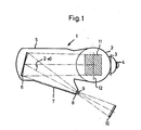
- the sun simulator 1 shown in FIG. 1 has a housing which is essentially composed of two cylindrical tanks 2 and 5 which are placed next to one another.
- the vertical standing tank 2 is provided with access openings 3 and 4 which can be closed in a vacuum-tight manner and through which the test space is accessible.
- tank 2 is the hatched drawing Test volume 11 in which the object to be tested is placed.
- the test volume 11 has the shape of a lying cylinder which extends symmetrically on both sides of the circular test plane 12.
- the horizontally lying tank 5 has a conical connection piece 7 on the side, the end face of which carries a vacuum-tight radiation window 8.
- a collimator mirror 6 is also arranged in the interior of the tank 5 and reflects the radiation passing through the window 8 at an angle 2oC onto the test plane 12.
- a large number of individual xenon high-pressure lamps combined to form a lamp array 10 are arranged outside the vacuum container 2/5. Their radiation is focused by an integrator module 9 made of field and projection lenses in the immediate vicinity of the radiation window 8.
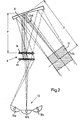
- the optics with the aid of which the light from the xenon high-pressure lamps is transmitted to the test plane 12 or the test volume 11 is shown in more detail in the main section.
- the integrator assembly 9 between the lamp array 10 and the collimator mirror 6 consists of two separate lens arrays arranged one behind the other, a field lens array 13 and a projection lens array 14, each array 13 and 14 containing a large number of individual lenses arranged side by side and one above the other.
- Each lens of the field lens array 13 images the entire lamp array 10 in each case one lens of the projection lens array 14, while each projection lens of the Arroys 14 respectively depicts an associated field lens in connection with the collimator mirror 6 in the test plane 12.
- the integrator assembly 9 is shown in greater detail in FIGS. 3 and 4. Thereafter, twenty-five field lenses 13 and twenty-five integrator lenses 14 are each inserted in a tight package in a rectangular plate 22 and 19 designed as a lens holder.
- the two plates 19 and 22 are kept apart by four bolts 20a-d.
- the plates 19 and 22 are traversed by cooling channels which are arranged by two plates 19 and 22 on both sides.
- the radiation bundle emanating from the integrator assembly 9 strikes the axis of the collimator mirror 6 at an angle ⁇ and is distorted in cross-sectional shape thereon.
- This distortion error is dependent on the angle of incidence k on the mirror and its radius of curvature r and its distance P from the integrator (projection range) and its distance T from the test plane (target distance). Since the cross-sections of the field lenses of the array 13 according to the prior art are circular, this distortion of distortion leads to the tuft cross-section in the test plane 12 being distorted in an elliptical manner, with the following being true for the axial ratio V of the ellipse:
- the border of all field lenses of the array 13 is elliptically shaped.
- FIG. 4 in which the arrows a and b, shown only as examples for the field lens 13b, indicate the different lengths of the two axes of the elliptically shaped field lenses.
- the longer axis a lies in the plane that is spanned by the bundle striking the mirror 6 and reflected by the mirror 6.
Landscapes
- Physics & Mathematics (AREA)
- Engineering & Computer Science (AREA)
- General Physics & Mathematics (AREA)
- Optics & Photonics (AREA)
- General Engineering & Computer Science (AREA)
- Mathematical Optimization (AREA)
- Pure & Applied Mathematics (AREA)
- Algebra (AREA)
- Computational Mathematics (AREA)
- Mathematical Analysis (AREA)
- Life Sciences & Earth Sciences (AREA)
- Mathematical Physics (AREA)
- Sustainable Development (AREA)
- Business, Economics & Management (AREA)
- Educational Administration (AREA)
- Educational Technology (AREA)
- Theoretical Computer Science (AREA)
- Testing Of Optical Devices Or Fibers (AREA)
- Lenses (AREA)
- Exposure And Positioning Against Photoresist Photosensitive Materials (AREA)
Abstract
Description
- Die Erfindung betrifft ein optisches System zur Übertragung von Strahlung hoher Intensität in eine Testebene. Solche optischen Systeme werden beispielsweise für sogenannte Sonnensimulatoren verwendet, d.h. Testeinrichtungen, in denen Raumflugkörper künstlich geschaffenen Weltraumbedingungen unterworfen werden, einschließlich eines der Sonnenstrahlung entsprechenden intensiven, einseitigen Strahlungsflusses.
- Zur Erzeugung der nötigen hohen Strahlungsintensität verwendet man dabei eine Vielzahl aneinandergereihter Hochleistungslampen, die einen Lichtfluß entsprechend mehreren 100 kW Leistung liefern. Dieser Lichtfluß wird über eine Integratorbaugruppe bestehend aus einem Array nebeneinander angeordneter Feldlinsen und eine ebensolche Anordnung von Projektionslinsen und über einen im Inneren des evakuierten Testraums aufgestellten Kollimatorspiegel auf das zu testende Objekt gerichtet. Dabei ist der Kollimatorspiegel in der Regel so angeordnet, daß er das vom Integrator kommende Strahlungsbündel "Off-Axis", d.h. unter einem Winkel zu seiner Symmetrieachse reflektiert.
- Bedingt durch diese Anordnung wird das nach dem Stand der Technik kreiskeglige Strahlungsbüschel, das den Integrator verläßt, durch den Kollimatorspiegel in ein Büschel mit elliptischem Querschnitt umgeformt. Im Testraum des Sonnensimulators sind jedoch in der Regel nur kreisförmige Querschnitte nutzbar. Das Licht außerhalb des in seiner Form vorgegebe- nen nutzbaren Bereiche der Testebene ist verloren und muß durch aufwendige Kühleinrichtungen beseitigt werden. Dieser Teil der Strahlung fehlt andererseits in der Testebene.
- Es ist die Aufgabe der vorliegenden Erfindung, das optische System der eingangs genannten Art so auszubilden, daß möglichst keine Strahlung außerhalb des vorgegebenen, nutzbaren Bereichs der Testebene anfällt. Diese Aufgabe wird gemäß den Merkmalen im Kennzeichen des Hauptanspruches dadurch gelöst, daß die Form der äußeren Umrandung der einzelnen Feldlinsen abweichend von der Kreisform so gewählt ist, daß unter Berücksichtigung der durch den Kollimatorspiegel eingeführten Verzeichnung die Querschnittsform des aus dem Kollimatorspiegel austretenden Strahlenbündels den vorgegebenen Abmessungen der Testebene entspricht.
- Gemäß der Erfindung wird also die Form des auf die Testebene auftreffenden Strahlungsbündels allein durch eine geeignete Wahl für die äußere Umrandung der Feldlinsen des Integrators angepaßt. Möglich ist die Beeinflußung der Form des auf die Testebene auftreffenden Strahlkegels an dieser Stelle, weil die Feldlinsen in einer zur Testebene konjugierten Ebene angeordnet sind, ihre Fassungen also einer Blende entsprechen, die in die Testebene vergrößert abgebildet wird.
- Die genaue Form der Umrandung läßt sich stets durch eine einfache Rechnung aus dem Krümmungsradius des Kollimatorspiegels, seiner Entfernung von Testebene und Integrator und dem Winkel zwischen seiner Achse und der des einfallenden Strahlungsbündels ermitteln. Beispielsweise wird für die Umrandung der Feldlinsen eine elliptische Form gewählt, wenn die vorgegebene Form der Testebene einen Kreis darstellt. Die längeren Achsen der Ellipse liegen dabei in der Ebene, die von den.Achsen des auf den Kollimatorspiegel einfallenden und reflektierten Strahlenbündels aufgespannt wird.
- Auch wenn für die Testebene eine andere Form vorgegeben ist, beispielsweise eine quadratische Form, läßt sich der Querschnitt des aus dem Kollimatorspiegel austretenden Büschels daran anpassen. Es ist dann eine kissenförmige Umrandung der Feldlinien vorzusehen.
- Die Form der Umrandung der Projektionslinsen, die bei Systemen der eingangs genannten Art den Feldlinsen nachgeschaltet sind, ist zweckmäßigerweise der der Feldlinsen angepaßt, um Lichtverluste in dem aus Feld-und Projektionslinsen bestehenden Integrator möglichst gering zu halten.
- Der mit der Erfindung erzielbare Vorteil ist in erster Linie darin zu sehen, daß in der Testebene nur dort Strahlung angeboten wird, wo sie auch benötigt wird. Aufwendige Kühleinrichtungen im Testraum selbst zur Vernichtung nicht benötigter Strahlungsanteile entfallen deshalb. Entsprechend ist der Wirkungsgrad eines gemäß der Erfindung aufgebauten Sonnensimulators verglichen mit einem nach dem Stand der Technik deutlich besser. Unter Wirkungsgrad wird der Quotient von eingespeister elektrischer Lampenleistung zu nutzbarer Lichtleistung in der Testebene verstanden.
- Ein weiterer Vorteil ist in der konstruktiven Unkompliziertheit der erfindungsgemäßen Lösung zu sehen, da keine zusätzlichen optischen Flächen eingeführt werden müssen, an denen zusätzliche Lichtverluste entstehen würden. Eingriffe am Kollimatorspiegel, der wegen seiner Größe und Stellung im evakuierten Inneren des Testraums ein kritisches und teures Bauelement darstellt, sind ebenfalls nicht erforderlich.
- Nachstehend wird ein Ausführungsbeispiel der vorliegenden Erfindung anhand der Figuren 1-4 der beigefügten Zeichnungen näher erläutert:
- Fig. 1 ist eine Prinzipskizze eines Sonnensimulators vom Off-Axis-Typ;
- Fig. 2 skizziert den Strahlengang in dem optischen System des Sonnensimulators nach Fig. 1 im Hauptschnitt;
- Fig. 3 ist eine im vergrößerten Maßstab dargestellte Detailzeichnung der Integratorbaugruppe 9 aus Fig. 2;
- Fig. 4 ist die Ansicht einer Hälfte der Feldlinsenanordnung des in Fig. 3 dargestellten Integrators.
- Der in Fig. dargestellte Sonnensimulator 1 besitzt ein im wesentlichen aus zwei aneinandergesetzten zylindrischen Tanks 2 und 5 aufgebautes Gehäuse. Der senkrechte stehende Tank 2 ist mit vakuumdicht verschließbaren Einstiegsöffnungen 3 und 4 versehen, über die der Testraum zugänglich ist. Dort, im Tank 2, befindet sich das schraffiert gezeichnete Testvolumen 11, in dem der zu prüfende Gegenstand plaziert wird. Das Testvolumen 11 hat die Form eines liegenden Zylinders, das sich symmetrisch beiderseits der kreisrunden Testebene 12 erstreckt.
- Der waagerecht liegende Tank 5 besitzt seitlich ein konisches Anschlußstück 7, dessen Stirnseite ein vakuumdichtes Strahlungsfenster 8 trägt. Im Inneren des Tanks 5 ist weiterhin ein Kollimatorspiegel 6 angeordnet, der die durch das Fenster 8 hindurchtretende Strahlung unter einem Winkel 2oCauf die Testebene 12 reflektiert.
- Zur Erzeugung des für die Simulation der Sonnenstrahlung nötigen intensiven Lichtflußes sind außerhalb des Vakuumbehälters 2/5 eine Vielzahl einzelner, zu einem Lampenorray 10 zusammengefaßte Xenon-Hochdrucklampen angeordnet. Deren Strahlung wird durch eine Integratorbaugruppe 9 aus Feld- und Projektionslinsen in unmittelbarer Nähe des Strahlungsfensters 8 gebündelt.
- In Fig. 2 ist die Optik, mit deren Hilfe das Licht der Xenon-Hochdrucklampen in die Testebene 12 bzw. das Testvolumen 11 übertragen wird, im Hauptschnitt detaillierter dargestellt. Daraus ist ersichtlich, daß die Integratorbaugruppe 9 zwischen dem Lampenarray 10 und dem Kollimatorspiegel 6 aus zwei hintereinander angeordneten, separaten Linsenarrays, einem Feldlinsenarray 13 und einem Projektionslinsenarray 14, besteht, wobei jedes Array 13 und 14 eine Vielzahl neben- und übereinander angeordnete Einzellinsen enthält. Jede Linse des Feldlinsenarrays 13 bildet das gesamte Lampenarray 10 in jeweils eine Linse des Projektionslinsenarrays 14 ab, während jede Projektionslinse des Arroys 14 jeweils eine ihr zugeordnete Feldlinse in Verbindung mit dem Kollimatorspiegel 6 in die Testebene 12 abbildet.
- In den Figuren 3 und 4 ist die Integratorbaugruppe 9 detaillierter dargestellt. Danach sind jeweils fünfundzwanzig Feldlinsen 13 und fünfundzwanzig Integratorlinsen 14 in dichter Packung in je eine als Linsenhalter ausgebildete, rechteckige Platte 22 bzw. 19 eingesetzt. Die beiden Platten 19 und 22 werden von vier Bolzen 20a-d auf Abstand gehalten. Zwischen den Linsen sind die Platten 19 und 22 von Kühlkanälen durchzogen, die von jeweils zwei beiderseits der Platten 19 und 22 angeordne- ten Verteilerkästen 15 und 16 bzw. 25 und 26 über Anschlußrohre 17118 bzw. 23/24 gespeist werden. Mit diesen Kühlkanälen wird die durch Absorption von Licht in den Linsen des Arroys 13 und 14 und deren Fassung entstehende Wärme abgeführt. Aus der Fig. 3 ist ebenfalls ersichtlich, daß die Feldlinsen des Arrays 13 abhängig von ihrer Stellung in Bezug auf die zentrisch angeordnete Linse 13a gegen den Rand des Arrays 13 hin mit einer prismatischen Wirkung versehen sind.
- Wie bereits erwähnt trifft das von der Integrotorbaugruppe 9 ausgehende Strahlungsbüschel unter einem Winkel α auf die Achse des Kollimatorspiegels 6 auf und wird an diesem in seiner Querschnittsform verzerrt. Dieser Verzeichnungsfehler ist abhängig vom Einfallswinkelk auf den Spiegel sowie dessen Krümmungsradius r und seinem Abstand P vom Integrator (Projektionsweite) und seinem Abstand T von der Testebene (Targetdistanz). Da die Querschnitte der Feldlinsen des Arrays 13 nach dem Stand der Technik kreisförmig sind, führt dieser Verzeichnungsfehler dazu, daß der Büschelquerschnitt in der Testebene 12 ellipsenförmig verzerrt ist, wobei für das Achsverhältnis V der Ellipse gilt:

- Um einen kreisförmigen Querschnitt des auf die Testebene 12 auftretenden Strahlungsbündel zu erzielen, ist gemäß der Erfindung die Umrandung aller Feldlinsen des Arrays 13 elliptisch geformt. Dies geht aus Fig. 4 hervor, in der die Pfeile a und b, beispielhaft nur für die Feldlinse 13b eingezeichnet, auf die unterschiedliche Länge der beiden Achsen der elliptisch geformten Feldlinsen hindeuten. Die längere Achse a liegt dabei in der Ebene, die durch das auf den Spiegel 6 auffallende und das vom Spiegel 6 reflektierte Bündel aufgespannt werden.
- In dem hier dargestellten, bevorzugten Ausführungsbeispiel sind für den Einfallswinkel α des auf den Kollimatorspiegel einfallenden Strahlungsbündels, den Krümmungsradius r des Kollimatorspiegels und für Targetdistanz T und Projektionsweite P folgende Werte gewählt:
- α = 29°
- = 30 m
- P = 17 m
- T = 14,667 m
- Daraus resultiert gemäß (1) ein Verzeichnungsfehler von 7,5%. Entsprechend ist das Achsverhöltnis der ellipsenförmigen Umrandung der Feldlinsen des Arrays 13 zu a:b = 1,075 gewählt, um den Verzeichnungsfehler zu kompensieren und es ergibt sich ein kreisrunder Querschnitt des auf die Testebene 12 auftreffenden Strahlungsbündels.
Claims (4)
Applications Claiming Priority (2)
| Application Number | Priority Date | Filing Date | Title |
|---|---|---|---|
| DE3437271 | 1984-10-11 | ||
| DE19843437271 DE3437271A1 (de) | 1984-10-11 | 1984-10-11 | Sonnensimulator |
Publications (3)
| Publication Number | Publication Date |
|---|---|
| EP0180800A2 true EP0180800A2 (de) | 1986-05-14 |
| EP0180800A3 EP0180800A3 (en) | 1987-07-22 |
| EP0180800B1 EP0180800B1 (de) | 1990-01-03 |
Family
ID=6247625
Family Applications (1)
| Application Number | Title | Priority Date | Filing Date |
|---|---|---|---|
| EP85112820A Expired - Lifetime EP0180800B1 (de) | 1984-10-11 | 1985-10-10 | Sonnensimulator |
Country Status (4)
| Country | Link |
|---|---|
| US (1) | US4701023A (de) |
| EP (1) | EP0180800B1 (de) |
| JP (1) | JPS6191615A (de) |
| DE (2) | DE3437271A1 (de) |
Cited By (3)
| Publication number | Priority date | Publication date | Assignee | Title |
|---|---|---|---|---|
| EP0563874A1 (de) * | 1992-03-31 | 1993-10-06 | Matsushita Electric Industrial Co., Ltd. | Optisches Beleuchtungssystem und eine dieses verwendende Projektionsanzeigevorrichtung |
| EP0683425A1 (de) * | 1994-05-16 | 1995-11-22 | Matsushita Electric Industrial Co., Ltd. | Projektionsanzeigevorrichtung |
| WO2012112276A3 (en) * | 2011-02-16 | 2012-12-27 | The Boeing Company | Method and apparatus for simulating solar light |
Families Citing this family (13)
| Publication number | Priority date | Publication date | Assignee | Title |
|---|---|---|---|---|
| US5568366A (en) * | 1994-10-11 | 1996-10-22 | The United States Of America As Represented By The Administrator Of The National Aeronautics And Space Administration | Compact solar simulator with a small subtense angle and controlled magnification optics |
| US5665305A (en) * | 1995-11-13 | 1997-09-09 | Belliveau; Richard S. | Lighting system with multiple beam shapes |
| US5980066A (en) * | 1997-06-04 | 1999-11-09 | High End Systems, Inc. | Lighting system with multiple beam shapes |
| US5984484A (en) | 1997-10-31 | 1999-11-16 | Trw Inc. | Large area pulsed solar simulator |
| JP4238390B2 (ja) * | 1998-02-27 | 2009-03-18 | 株式会社ニコン | 照明装置、該照明装置を備えた露光装置および該露光装置を用いて半導体デバイスを製造する方法 |
| US6505957B2 (en) * | 2001-03-09 | 2003-01-14 | Prokia Technology Co., Ltd. | Illuminating apparatus for a projection display |
| TWI355520B (en) | 2008-08-21 | 2012-01-01 | All Real Technology Co Ltd | Artificial light source generator |
| RU2468342C1 (ru) * | 2011-03-31 | 2012-11-27 | Открытое акционерное общество "Информационные спутниковые системы" имени академика М.Ф. Решетнёва" | Неосевой имитатор солнечного излучения тепловакуумной камеры |
| DE102011051590A1 (de) * | 2011-07-05 | 2013-01-10 | Jena-Optronik Gmbh | Extraterrestrisches optisches Instrument mit mikrooptischem Strahlformungselement und Verfahren zu dessen Kalibration |
| ITTO20120988A1 (it) * | 2012-11-14 | 2014-05-15 | Light In Light S R L | Sistema di illuminazione artificiale per simulare un'illuminazione naturale |
| CN103267248A (zh) * | 2013-06-03 | 2013-08-28 | 中国科学院长春光学精密机械与物理研究所 | 离轴角29°~45°的大辐照面积环境试验用太阳模拟器装置 |
| CN104914571A (zh) * | 2014-03-12 | 2015-09-16 | 南京理工大学 | 太阳模拟器光学系统 |
| CN104749089A (zh) * | 2015-02-06 | 2015-07-01 | 北京环境特性研究所 | 一种使用无热沉准直镜的太阳模拟器 |
Family Cites Families (8)
| Publication number | Priority date | Publication date | Assignee | Title |
|---|---|---|---|---|
| DE968430C (de) * | 1937-01-28 | 1958-02-13 | Zeiss Ikon Ag | Beleuchtungsvorrichtung fuer Projektionsbildgeraete |
| DE1721435U (de) * | 1955-04-28 | 1956-05-03 | Zeiss Ikon Dresden Veb | Beleuchtungseinrichtung mit wabenkondensor fuer breitbildprojektion. |
| FR1394183A (fr) * | 1964-02-18 | 1965-04-02 | Anciens Ets Barbier | Dispositifs condenseurs de rayonnement perfectionnés |
| NL7706379A (nl) * | 1977-06-10 | 1978-12-12 | Philips Nv | Werkwijze voor de vervaardiging van een koppelelement. |
| DE2803277A1 (de) * | 1978-01-26 | 1979-08-02 | Bosch Gmbh Robert | Vorrichtung zur belichtung einer auf eine oberflaeche eines substrats aufgebrachten fotolackschicht |
| US4306810A (en) * | 1978-05-12 | 1981-12-22 | Maddox Darryl W | Apparatuses and method for paleocurrent direction determination using reflected light |
| DE3300811A1 (de) * | 1983-01-12 | 1984-07-12 | Agence Spatiale Européene, Paris | Sammeloptik fuer hochleistungs-lichtquellen |
| DE3325581A1 (de) * | 1983-07-15 | 1985-01-24 | Fa. Carl Zeiss, 7920 Heidenheim | Vakuumdichtes strahlungsfenster |
-
1984
- 1984-10-11 DE DE19843437271 patent/DE3437271A1/de not_active Withdrawn
-
1985
- 1985-10-10 EP EP85112820A patent/EP0180800B1/de not_active Expired - Lifetime
- 1985-10-10 DE DE8585112820T patent/DE3575209D1/de not_active Expired - Fee Related
- 1985-10-11 US US06/786,660 patent/US4701023A/en not_active Expired - Fee Related
- 1985-10-11 JP JP60225010A patent/JPS6191615A/ja active Pending
Cited By (6)
| Publication number | Priority date | Publication date | Assignee | Title |
|---|---|---|---|---|
| EP0563874A1 (de) * | 1992-03-31 | 1993-10-06 | Matsushita Electric Industrial Co., Ltd. | Optisches Beleuchtungssystem und eine dieses verwendende Projektionsanzeigevorrichtung |
| US5418583A (en) * | 1992-03-31 | 1995-05-23 | Matsushita Electric Industrial Co., Ltd. | Optical illumination system and projection display apparatus using the same |
| EP0683425A1 (de) * | 1994-05-16 | 1995-11-22 | Matsushita Electric Industrial Co., Ltd. | Projektionsanzeigevorrichtung |
| US5649753A (en) * | 1994-05-16 | 1997-07-22 | Matsushita Electric Industrial Co., Ltd. | Projection display apparatus |
| WO2012112276A3 (en) * | 2011-02-16 | 2012-12-27 | The Boeing Company | Method and apparatus for simulating solar light |
| US8439530B2 (en) | 2011-02-16 | 2013-05-14 | The Boeing Company | Method and apparatus for simulating solar light |
Also Published As
| Publication number | Publication date |
|---|---|
| US4701023A (en) | 1987-10-20 |
| EP0180800B1 (de) | 1990-01-03 |
| JPS6191615A (ja) | 1986-05-09 |
| DE3575209D1 (de) | 1990-02-08 |
| DE3437271A1 (de) | 1986-04-17 |
| EP0180800A3 (en) | 1987-07-22 |
Similar Documents
| Publication | Publication Date | Title |
|---|---|---|
| EP0180800B1 (de) | Sonnensimulator | |
| EP1354325B1 (de) | KOLLEKTOR MIT UNGENUTZTEM BEREICH FÜR BELEUCHTUNGSSYSTEME MIT EINER WELLENLÄNGE KLEINER ODER GLEICH 193 nm. | |
| DE69529866T2 (de) | Apparat zur gleichmässigen Beleuchtung eines Lichtventils | |
| DE69425204T2 (de) | Beleuchtungssystem | |
| DE3001059A1 (de) | Roentgenstrahlenlithographiesystem mit einer collimations-optik | |
| EP0923747A1 (de) | Optisches strahlformungssystem | |
| DE112014004124B4 (de) | Laserabtastvorrichtung | |
| EP1180726B1 (de) | Beleuchtungssystem für die Mikrolithographie | |
| DE19635792A1 (de) | Zoomvorrichtung | |
| DE102011115141A1 (de) | Solar-Simulator | |
| DE19734983A1 (de) | Optische Anordnung | |
| EP0086790B1 (de) | Einrichtung zur projektion von stereoskopischen, anamorphotisch komprimierten bildpaaren auf eine sphärisch gekrümmte breitwandfläche | |
| EP0923749A1 (de) | Lichtübertragungsvorrichtung | |
| DE112011102900B4 (de) | Abbildungssystem | |
| DE2906440A1 (de) | Spektrometer | |
| DE1279859B (de) | Einrichtung zur Erzeugung von Neutronen aus Kernfusionsreaktionen | |
| DE102013114083A1 (de) | Vorrichtung zur Formung von Laserstrahlung | |
| EP2890974A1 (de) | Vorrichtung zum inspizieren von gegenständen | |
| DE3938938C2 (de) | Episkop | |
| DE19734059A1 (de) | Anordnung für Schattenwurflithographie | |
| DE2036369B2 (de) | Spiegelobjektiv mit einem konvexen sphärischen und einem mit einer Öffnung versehenen konkaven sphärischen Spiegel | |
| DE3881740T2 (de) | Optisches Entfernungsmessystem. | |
| WO2000014582A2 (de) | Abschlussstück für lichtleitfasern | |
| DE3325581A1 (de) | Vakuumdichtes strahlungsfenster | |
| DE1948344A1 (de) | Vorrichtung zur Unterdrueckung der Rueckstrahlung von auf ein Target fallendem Laserlicht |
Legal Events
| Date | Code | Title | Description |
|---|---|---|---|
| PUAI | Public reference made under article 153(3) epc to a published international application that has entered the european phase |
Free format text: ORIGINAL CODE: 0009012 |
|
| AK | Designated contracting states |
Kind code of ref document: A2 Designated state(s): DE FR GB IT |
|
| RAP1 | Party data changed (applicant data changed or rights of an application transferred) |
Owner name: CARL-ZEISS-STIFTUNG TRADING AS CARL ZEISS Owner name: FIRMA CARL ZEISS |
|
| PUAL | Search report despatched |
Free format text: ORIGINAL CODE: 0009013 |
|
| AK | Designated contracting states |
Kind code of ref document: A3 Designated state(s): DE FR GB IT |
|
| 17P | Request for examination filed |
Effective date: 19870724 |
|
| 17Q | First examination report despatched |
Effective date: 19880922 |
|
| 17Q | First examination report despatched |
Effective date: 19890605 |
|
| ITF | It: translation for a ep patent filed | ||
| GRAA | (expected) grant |
Free format text: ORIGINAL CODE: 0009210 |
|
| AK | Designated contracting states |
Kind code of ref document: B1 Designated state(s): DE FR GB IT |
|
| REF | Corresponds to: |
Ref document number: 3575209 Country of ref document: DE Date of ref document: 19900208 |
|
| ET | Fr: translation filed | ||
| GBT | Gb: translation of ep patent filed (gb section 77(6)(a)/1977) | ||
| PLBE | No opposition filed within time limit |
Free format text: ORIGINAL CODE: 0009261 |
|
| STAA | Information on the status of an ep patent application or granted ep patent |
Free format text: STATUS: NO OPPOSITION FILED WITHIN TIME LIMIT |
|
| 26N | No opposition filed | ||
| PGFP | Annual fee paid to national office [announced via postgrant information from national office to epo] |
Ref country code: GB Payment date: 19921005 Year of fee payment: 8 |
|
| PGFP | Annual fee paid to national office [announced via postgrant information from national office to epo] |
Ref country code: FR Payment date: 19930921 Year of fee payment: 9 |
|
| PGFP | Annual fee paid to national office [announced via postgrant information from national office to epo] |
Ref country code: DE Payment date: 19930927 Year of fee payment: 9 |
|
| PG25 | Lapsed in a contracting state [announced via postgrant information from national office to epo] |
Ref country code: GB Effective date: 19931010 |
|
| ITTA | It: last paid annual fee | ||
| GBPC | Gb: european patent ceased through non-payment of renewal fee |
Effective date: 19931010 |
|
| PG25 | Lapsed in a contracting state [announced via postgrant information from national office to epo] |
Ref country code: FR Effective date: 19950630 |
|
| PG25 | Lapsed in a contracting state [announced via postgrant information from national office to epo] |
Ref country code: DE Effective date: 19950701 |
|
| REG | Reference to a national code |
Ref country code: FR Ref legal event code: ST |