EP0180800A2 - Simulateur du soleil - Google Patents
Simulateur du soleil Download PDFInfo
- Publication number
- EP0180800A2 EP0180800A2 EP85112820A EP85112820A EP0180800A2 EP 0180800 A2 EP0180800 A2 EP 0180800A2 EP 85112820 A EP85112820 A EP 85112820A EP 85112820 A EP85112820 A EP 85112820A EP 0180800 A2 EP0180800 A2 EP 0180800A2
- Authority
- EP
- European Patent Office
- Prior art keywords
- test
- shape
- collimator mirror
- field lenses
- test plane
- Prior art date
- Legal status (The legal status is an assumption and is not a legal conclusion. Google has not performed a legal analysis and makes no representation as to the accuracy of the status listed.)
- Granted
Links
- 230000005855 radiation Effects 0.000 claims abstract description 23
- 230000003287 optical effect Effects 0.000 claims description 9
- 238000011144 upstream manufacturing Methods 0.000 claims 1
- 238000001816 cooling Methods 0.000 description 4
- 230000004907 flux Effects 0.000 description 2
- 229910052724 xenon Inorganic materials 0.000 description 2
- FHNFHKCVQCLJFQ-UHFFFAOYSA-N xenon atom Chemical compound [Xe] FHNFHKCVQCLJFQ-UHFFFAOYSA-N 0.000 description 2
- 238000003491 array Methods 0.000 description 1
- 238000004364 calculation method Methods 0.000 description 1
- 230000001419 dependent effect Effects 0.000 description 1
- 238000010586 diagram Methods 0.000 description 1
- 230000000694 effects Effects 0.000 description 1
- 230000031700 light absorption Effects 0.000 description 1
- 238000004088 simulation Methods 0.000 description 1
Images


Classifications
-
- G—PHYSICS
- G02—OPTICS
- G02B—OPTICAL ELEMENTS, SYSTEMS OR APPARATUS
- G02B27/00—Optical systems or apparatus not provided for by any of the groups G02B1/00 - G02B26/00, G02B30/00
- G02B27/09—Beam shaping, e.g. changing the cross-sectional area, not otherwise provided for
- G02B27/0938—Using specific optical elements
- G02B27/0977—Reflective elements
- G02B27/0983—Reflective elements being curved
-
- F—MECHANICAL ENGINEERING; LIGHTING; HEATING; WEAPONS; BLASTING
- F21—LIGHTING
- F21S—NON-PORTABLE LIGHTING DEVICES; SYSTEMS THEREOF; VEHICLE LIGHTING DEVICES SPECIALLY ADAPTED FOR VEHICLE EXTERIORS
- F21S8/00—Lighting devices intended for fixed installation
- F21S8/006—Solar simulators, e.g. for testing photovoltaic panels
-
- F—MECHANICAL ENGINEERING; LIGHTING; HEATING; WEAPONS; BLASTING
- F21—LIGHTING
- F21V—FUNCTIONAL FEATURES OR DETAILS OF LIGHTING DEVICES OR SYSTEMS THEREOF; STRUCTURAL COMBINATIONS OF LIGHTING DEVICES WITH OTHER ARTICLES, NOT OTHERWISE PROVIDED FOR
- F21V13/00—Producing particular characteristics or distribution of the light emitted by means of a combination of elements specified in two or more of main groups F21V1/00 - F21V11/00
- F21V13/02—Combinations of only two kinds of elements
- F21V13/04—Combinations of only two kinds of elements the elements being reflectors and refractors
-
- G—PHYSICS
- G02—OPTICS
- G02B—OPTICAL ELEMENTS, SYSTEMS OR APPARATUS
- G02B27/00—Optical systems or apparatus not provided for by any of the groups G02B1/00 - G02B26/00, G02B30/00
- G02B27/09—Beam shaping, e.g. changing the cross-sectional area, not otherwise provided for
- G02B27/0938—Using specific optical elements
- G02B27/095—Refractive optical elements
- G02B27/0955—Lenses
- G02B27/0961—Lens arrays
-
- G—PHYSICS
- G09—EDUCATION; CRYPTOGRAPHY; DISPLAY; ADVERTISING; SEALS
- G09B—EDUCATIONAL OR DEMONSTRATION APPLIANCES; APPLIANCES FOR TEACHING, OR COMMUNICATING WITH, THE BLIND, DEAF OR MUTE; MODELS; PLANETARIA; GLOBES; MAPS; DIAGRAMS
- G09B23/00—Models for scientific, medical, or mathematical purposes, e.g. full-sized devices for demonstration purposes
- G09B23/06—Models for scientific, medical, or mathematical purposes, e.g. full-sized devices for demonstration purposes for physics
- G09B23/22—Models for scientific, medical, or mathematical purposes, e.g. full-sized devices for demonstration purposes for physics for optics
-
- B—PERFORMING OPERATIONS; TRANSPORTING
- B64—AIRCRAFT; AVIATION; COSMONAUTICS
- B64G—COSMONAUTICS; VEHICLES OR EQUIPMENT THEREFOR
- B64G7/00—Simulating cosmonautic conditions, e.g. for conditioning crews
- B64G2007/005—Space simulation vacuum chambers
Definitions
- the invention relates to an optical system for transmitting radiation of high intensity in a test plane.
- optical systems are used, for example, for so-called sun simulators, i.e. Test facilities in which spacecraft are subjected to artificially created space conditions, including an intense, one-sided radiation flow corresponding to solar radiation.
- a large number of high-performance lamps are used, which provide a light flow corresponding to several 100 kW of power.
- This light flux is directed via an integrator assembly consisting of an array of field lenses arranged next to one another and the same arrangement of projection lenses and via a collimator mirror set up inside the evacuated test room onto the object to be tested.
- the collimator mirror is usually arranged so that it detects the radiation beam coming from the integrator "off-axis", i.e. reflected at an angle to its axis of symmetry.
- This object is achieved according to the features in the characterizing part of the main claim in that the shape of the outer border of the individual field lenses is chosen differently from the circular shape so that, taking into account the distortion introduced by the collimator mirror, the cross-sectional shape of the beam emerging from the collimator mirror corresponds to the given dimensions corresponds to the test level.
- the shape of the radiation beam impinging on the test plane is therefore adjusted solely by a suitable choice for the outer border of the field lenses of the integrator. It is possible to influence the shape of the beam cone impinging on the test plane at this point because the field lenses are arranged in a plane conjugate to the test plane, so their frames correspond to an aperture that is shown enlarged in the test plane.
- the exact shape of the border can always be determined by a simple calculation from the radius of curvature of the collimator mirror, its distance from the test plane and integrator and the angle between its axis and that of the incident radiation beam. For example, an elliptical shape is selected for the border of the field lenses if the predetermined shape of the test plane represents a circle. The longer axes of the ellipse lie in the plane that is spanned by the axes of the beam of rays incident and reflected on the collimator mirror.
- test plane for example a square shape
- cross section of the tuft emerging from the collimator mirror can be adapted to it.
- a pillow-shaped outline of the field lines must then be provided.
- the shape of the border of the projection lenses which are connected downstream of the field lenses in systems of the type mentioned, is expediently adapted to that of the field lenses in order to keep light losses in the integrator consisting of field and projection lenses as low as possible.
- the advantage achievable with the invention is primarily in it see that in the test level radiation is only offered where it is needed. This eliminates the need for complex cooling devices in the test room itself to destroy radiation components that are not required. Accordingly, the efficiency of a sun simulator constructed according to the invention is significantly better compared to that according to the prior art. Efficiency is understood to be the quotient of electrical lamp power fed in to usable light power in the test level.
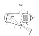
- the sun simulator 1 shown in FIG. 1 has a housing which is essentially composed of two cylindrical tanks 2 and 5 which are placed next to one another.
- the vertical standing tank 2 is provided with access openings 3 and 4 which can be closed in a vacuum-tight manner and through which the test space is accessible.
- tank 2 is the hatched drawing Test volume 11 in which the object to be tested is placed.
- the test volume 11 has the shape of a lying cylinder which extends symmetrically on both sides of the circular test plane 12.
- the horizontally lying tank 5 has a conical connection piece 7 on the side, the end face of which carries a vacuum-tight radiation window 8.
- a collimator mirror 6 is also arranged in the interior of the tank 5 and reflects the radiation passing through the window 8 at an angle 2oC onto the test plane 12.
- a large number of individual xenon high-pressure lamps combined to form a lamp array 10 are arranged outside the vacuum container 2/5. Their radiation is focused by an integrator module 9 made of field and projection lenses in the immediate vicinity of the radiation window 8.
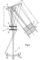
- the optics with the aid of which the light from the xenon high-pressure lamps is transmitted to the test plane 12 or the test volume 11 is shown in more detail in the main section.
- the integrator assembly 9 between the lamp array 10 and the collimator mirror 6 consists of two separate lens arrays arranged one behind the other, a field lens array 13 and a projection lens array 14, each array 13 and 14 containing a large number of individual lenses arranged side by side and one above the other.
- Each lens of the field lens array 13 images the entire lamp array 10 in each case one lens of the projection lens array 14, while each projection lens of the Arroys 14 respectively depicts an associated field lens in connection with the collimator mirror 6 in the test plane 12.
- the integrator assembly 9 is shown in greater detail in FIGS. 3 and 4. Thereafter, twenty-five field lenses 13 and twenty-five integrator lenses 14 are each inserted in a tight package in a rectangular plate 22 and 19 designed as a lens holder.
- the two plates 19 and 22 are kept apart by four bolts 20a-d.
- the plates 19 and 22 are traversed by cooling channels which are arranged by two plates 19 and 22 on both sides.
- the radiation bundle emanating from the integrator assembly 9 strikes the axis of the collimator mirror 6 at an angle ⁇ and is distorted in cross-sectional shape thereon.
- This distortion error is dependent on the angle of incidence k on the mirror and its radius of curvature r and its distance P from the integrator (projection range) and its distance T from the test plane (target distance). Since the cross-sections of the field lenses of the array 13 according to the prior art are circular, this distortion of distortion leads to the tuft cross-section in the test plane 12 being distorted in an elliptical manner, with the following being true for the axial ratio V of the ellipse:
- the border of all field lenses of the array 13 is elliptically shaped.
- FIG. 4 in which the arrows a and b, shown only as examples for the field lens 13b, indicate the different lengths of the two axes of the elliptically shaped field lenses.
- the longer axis a lies in the plane that is spanned by the bundle striking the mirror 6 and reflected by the mirror 6.
Landscapes
- Physics & Mathematics (AREA)
- Engineering & Computer Science (AREA)
- General Physics & Mathematics (AREA)
- Optics & Photonics (AREA)
- General Engineering & Computer Science (AREA)
- Mathematical Optimization (AREA)
- Pure & Applied Mathematics (AREA)
- Algebra (AREA)
- Computational Mathematics (AREA)
- Mathematical Analysis (AREA)
- Life Sciences & Earth Sciences (AREA)
- Mathematical Physics (AREA)
- Sustainable Development (AREA)
- Business, Economics & Management (AREA)
- Educational Administration (AREA)
- Educational Technology (AREA)
- Theoretical Computer Science (AREA)
- Testing Of Optical Devices Or Fibers (AREA)
- Lenses (AREA)
- Exposure And Positioning Against Photoresist Photosensitive Materials (AREA)
Applications Claiming Priority (2)
| Application Number | Priority Date | Filing Date | Title |
|---|---|---|---|
| DE3437271 | 1984-10-11 | ||
| DE19843437271 DE3437271A1 (de) | 1984-10-11 | 1984-10-11 | Sonnensimulator |
Publications (3)
| Publication Number | Publication Date |
|---|---|
| EP0180800A2 true EP0180800A2 (fr) | 1986-05-14 |
| EP0180800A3 EP0180800A3 (en) | 1987-07-22 |
| EP0180800B1 EP0180800B1 (fr) | 1990-01-03 |
Family
ID=6247625
Family Applications (1)
| Application Number | Title | Priority Date | Filing Date |
|---|---|---|---|
| EP85112820A Expired - Lifetime EP0180800B1 (fr) | 1984-10-11 | 1985-10-10 | Simulateur du soleil |
Country Status (4)
| Country | Link |
|---|---|
| US (1) | US4701023A (fr) |
| EP (1) | EP0180800B1 (fr) |
| JP (1) | JPS6191615A (fr) |
| DE (2) | DE3437271A1 (fr) |
Cited By (3)
| Publication number | Priority date | Publication date | Assignee | Title |
|---|---|---|---|---|
| EP0563874A1 (fr) * | 1992-03-31 | 1993-10-06 | Matsushita Electric Industrial Co., Ltd. | Système d'éclairage optique et dispositif d'affichage par projection l'utilisant |
| EP0683425A1 (fr) * | 1994-05-16 | 1995-11-22 | Matsushita Electric Industrial Co., Ltd. | Dispositif d'affichage par projection |
| WO2012112276A3 (fr) * | 2011-02-16 | 2012-12-27 | The Boeing Company | Procédé et appareil de simulation de lumière solaire |
Families Citing this family (13)
| Publication number | Priority date | Publication date | Assignee | Title |
|---|---|---|---|---|
| US5568366A (en) * | 1994-10-11 | 1996-10-22 | The United States Of America As Represented By The Administrator Of The National Aeronautics And Space Administration | Compact solar simulator with a small subtense angle and controlled magnification optics |
| US5665305A (en) * | 1995-11-13 | 1997-09-09 | Belliveau; Richard S. | Lighting system with multiple beam shapes |
| US5980066A (en) * | 1997-06-04 | 1999-11-09 | High End Systems, Inc. | Lighting system with multiple beam shapes |
| US5984484A (en) | 1997-10-31 | 1999-11-16 | Trw Inc. | Large area pulsed solar simulator |
| JP4238390B2 (ja) * | 1998-02-27 | 2009-03-18 | 株式会社ニコン | 照明装置、該照明装置を備えた露光装置および該露光装置を用いて半導体デバイスを製造する方法 |
| US6505957B2 (en) * | 2001-03-09 | 2003-01-14 | Prokia Technology Co., Ltd. | Illuminating apparatus for a projection display |
| TWI355520B (en) | 2008-08-21 | 2012-01-01 | All Real Technology Co Ltd | Artificial light source generator |
| RU2468342C1 (ru) * | 2011-03-31 | 2012-11-27 | Открытое акционерное общество "Информационные спутниковые системы" имени академика М.Ф. Решетнёва" | Неосевой имитатор солнечного излучения тепловакуумной камеры |
| DE102011051590A1 (de) * | 2011-07-05 | 2013-01-10 | Jena-Optronik Gmbh | Extraterrestrisches optisches Instrument mit mikrooptischem Strahlformungselement und Verfahren zu dessen Kalibration |
| ITTO20120988A1 (it) * | 2012-11-14 | 2014-05-15 | Light In Light S R L | Sistema di illuminazione artificiale per simulare un'illuminazione naturale |
| CN103267248A (zh) * | 2013-06-03 | 2013-08-28 | 中国科学院长春光学精密机械与物理研究所 | 离轴角29°~45°的大辐照面积环境试验用太阳模拟器装置 |
| CN104914571A (zh) * | 2014-03-12 | 2015-09-16 | 南京理工大学 | 太阳模拟器光学系统 |
| CN104749089A (zh) * | 2015-02-06 | 2015-07-01 | 北京环境特性研究所 | 一种使用无热沉准直镜的太阳模拟器 |
Family Cites Families (8)
| Publication number | Priority date | Publication date | Assignee | Title |
|---|---|---|---|---|
| DE968430C (de) * | 1937-01-28 | 1958-02-13 | Zeiss Ikon Ag | Beleuchtungsvorrichtung fuer Projektionsbildgeraete |
| DE1721435U (de) * | 1955-04-28 | 1956-05-03 | Zeiss Ikon Dresden Veb | Beleuchtungseinrichtung mit wabenkondensor fuer breitbildprojektion. |
| FR1394183A (fr) * | 1964-02-18 | 1965-04-02 | Anciens Ets Barbier | Dispositifs condenseurs de rayonnement perfectionnés |
| NL7706379A (nl) * | 1977-06-10 | 1978-12-12 | Philips Nv | Werkwijze voor de vervaardiging van een koppelelement. |
| DE2803277A1 (de) * | 1978-01-26 | 1979-08-02 | Bosch Gmbh Robert | Vorrichtung zur belichtung einer auf eine oberflaeche eines substrats aufgebrachten fotolackschicht |
| US4306810A (en) * | 1978-05-12 | 1981-12-22 | Maddox Darryl W | Apparatuses and method for paleocurrent direction determination using reflected light |
| DE3300811A1 (de) * | 1983-01-12 | 1984-07-12 | Agence Spatiale Européene, Paris | Sammeloptik fuer hochleistungs-lichtquellen |
| DE3325581A1 (de) * | 1983-07-15 | 1985-01-24 | Fa. Carl Zeiss, 7920 Heidenheim | Vakuumdichtes strahlungsfenster |
-
1984
- 1984-10-11 DE DE19843437271 patent/DE3437271A1/de not_active Withdrawn
-
1985
- 1985-10-10 EP EP85112820A patent/EP0180800B1/fr not_active Expired - Lifetime
- 1985-10-10 DE DE8585112820T patent/DE3575209D1/de not_active Expired - Fee Related
- 1985-10-11 US US06/786,660 patent/US4701023A/en not_active Expired - Fee Related
- 1985-10-11 JP JP60225010A patent/JPS6191615A/ja active Pending
Cited By (6)
| Publication number | Priority date | Publication date | Assignee | Title |
|---|---|---|---|---|
| EP0563874A1 (fr) * | 1992-03-31 | 1993-10-06 | Matsushita Electric Industrial Co., Ltd. | Système d'éclairage optique et dispositif d'affichage par projection l'utilisant |
| US5418583A (en) * | 1992-03-31 | 1995-05-23 | Matsushita Electric Industrial Co., Ltd. | Optical illumination system and projection display apparatus using the same |
| EP0683425A1 (fr) * | 1994-05-16 | 1995-11-22 | Matsushita Electric Industrial Co., Ltd. | Dispositif d'affichage par projection |
| US5649753A (en) * | 1994-05-16 | 1997-07-22 | Matsushita Electric Industrial Co., Ltd. | Projection display apparatus |
| WO2012112276A3 (fr) * | 2011-02-16 | 2012-12-27 | The Boeing Company | Procédé et appareil de simulation de lumière solaire |
| US8439530B2 (en) | 2011-02-16 | 2013-05-14 | The Boeing Company | Method and apparatus for simulating solar light |
Also Published As
| Publication number | Publication date |
|---|---|
| US4701023A (en) | 1987-10-20 |
| EP0180800B1 (fr) | 1990-01-03 |
| JPS6191615A (ja) | 1986-05-09 |
| DE3575209D1 (de) | 1990-02-08 |
| DE3437271A1 (de) | 1986-04-17 |
| EP0180800A3 (en) | 1987-07-22 |
Similar Documents
| Publication | Publication Date | Title |
|---|---|---|
| EP0180800B1 (fr) | Simulateur du soleil | |
| EP1354325B1 (fr) | Collecteur presentant une zone inutilisee, destine a des systemes d'eclairage de longueur d'onde inferieur ou egal a 193 nm. | |
| DE69529866T2 (de) | Apparat zur gleichmässigen Beleuchtung eines Lichtventils | |
| DE69425204T2 (de) | Beleuchtungssystem | |
| DE3001059A1 (de) | Roentgenstrahlenlithographiesystem mit einer collimations-optik | |
| EP0923747A1 (fr) | Systeme de formation de faisceau optique | |
| DE112014004124B4 (de) | Laserabtastvorrichtung | |
| EP1180726B1 (fr) | Système d' illumination pour la microlithographie | |
| DE19635792A1 (de) | Zoomvorrichtung | |
| DE102011115141A1 (de) | Solar-Simulator | |
| DE19734983A1 (de) | Optische Anordnung | |
| EP0086790B1 (fr) | Installation de projection de paires d'images stereoscopiques anamorphotiquement comprimees sur une surface spherique | |
| EP0923749A1 (fr) | Dispositif de transmission de lumiere | |
| DE112011102900B4 (de) | Abbildungssystem | |
| DE2906440A1 (de) | Spektrometer | |
| DE1279859B (de) | Einrichtung zur Erzeugung von Neutronen aus Kernfusionsreaktionen | |
| DE102013114083A1 (de) | Vorrichtung zur Formung von Laserstrahlung | |
| EP2890974A1 (fr) | Dispositif servant à inspecter des objets | |
| DE3938938C2 (de) | Episkop | |
| DE19734059A1 (de) | Anordnung für Schattenwurflithographie | |
| DE2036369B2 (de) | Spiegelobjektiv mit einem konvexen sphärischen und einem mit einer Öffnung versehenen konkaven sphärischen Spiegel | |
| DE3881740T2 (de) | Optisches Entfernungsmessystem. | |
| WO2000014582A2 (fr) | Embout pour fibres optiques | |
| DE3325581A1 (de) | Vakuumdichtes strahlungsfenster | |
| DE1948344A1 (de) | Vorrichtung zur Unterdrueckung der Rueckstrahlung von auf ein Target fallendem Laserlicht |
Legal Events
| Date | Code | Title | Description |
|---|---|---|---|
| PUAI | Public reference made under article 153(3) epc to a published international application that has entered the european phase |
Free format text: ORIGINAL CODE: 0009012 |
|
| AK | Designated contracting states |
Kind code of ref document: A2 Designated state(s): DE FR GB IT |
|
| RAP1 | Party data changed (applicant data changed or rights of an application transferred) |
Owner name: CARL-ZEISS-STIFTUNG TRADING AS CARL ZEISS Owner name: FIRMA CARL ZEISS |
|
| PUAL | Search report despatched |
Free format text: ORIGINAL CODE: 0009013 |
|
| AK | Designated contracting states |
Kind code of ref document: A3 Designated state(s): DE FR GB IT |
|
| 17P | Request for examination filed |
Effective date: 19870724 |
|
| 17Q | First examination report despatched |
Effective date: 19880922 |
|
| 17Q | First examination report despatched |
Effective date: 19890605 |
|
| ITF | It: translation for a ep patent filed | ||
| GRAA | (expected) grant |
Free format text: ORIGINAL CODE: 0009210 |
|
| AK | Designated contracting states |
Kind code of ref document: B1 Designated state(s): DE FR GB IT |
|
| REF | Corresponds to: |
Ref document number: 3575209 Country of ref document: DE Date of ref document: 19900208 |
|
| ET | Fr: translation filed | ||
| GBT | Gb: translation of ep patent filed (gb section 77(6)(a)/1977) | ||
| PLBE | No opposition filed within time limit |
Free format text: ORIGINAL CODE: 0009261 |
|
| STAA | Information on the status of an ep patent application or granted ep patent |
Free format text: STATUS: NO OPPOSITION FILED WITHIN TIME LIMIT |
|
| 26N | No opposition filed | ||
| PGFP | Annual fee paid to national office [announced via postgrant information from national office to epo] |
Ref country code: GB Payment date: 19921005 Year of fee payment: 8 |
|
| PGFP | Annual fee paid to national office [announced via postgrant information from national office to epo] |
Ref country code: FR Payment date: 19930921 Year of fee payment: 9 |
|
| PGFP | Annual fee paid to national office [announced via postgrant information from national office to epo] |
Ref country code: DE Payment date: 19930927 Year of fee payment: 9 |
|
| PG25 | Lapsed in a contracting state [announced via postgrant information from national office to epo] |
Ref country code: GB Effective date: 19931010 |
|
| ITTA | It: last paid annual fee | ||
| GBPC | Gb: european patent ceased through non-payment of renewal fee |
Effective date: 19931010 |
|
| PG25 | Lapsed in a contracting state [announced via postgrant information from national office to epo] |
Ref country code: FR Effective date: 19950630 |
|
| PG25 | Lapsed in a contracting state [announced via postgrant information from national office to epo] |
Ref country code: DE Effective date: 19950701 |
|
| REG | Reference to a national code |
Ref country code: FR Ref legal event code: ST |