EP0180847A1 - Boîtier de commande pour culasse des moteurs à combustion interne avec des soupapes agencées en parallèle - Google Patents
Boîtier de commande pour culasse des moteurs à combustion interne avec des soupapes agencées en parallèle Download PDFInfo
- Publication number
- EP0180847A1 EP0180847A1 EP85113420A EP85113420A EP0180847A1 EP 0180847 A1 EP0180847 A1 EP 0180847A1 EP 85113420 A EP85113420 A EP 85113420A EP 85113420 A EP85113420 A EP 85113420A EP 0180847 A1 EP0180847 A1 EP 0180847A1
- Authority
- EP
- European Patent Office
- Prior art keywords
- bearing
- web
- control housing
- camshaft
- cylinder head
- Prior art date
- Legal status (The legal status is an assumption and is not a legal conclusion. Google has not performed a legal analysis and makes no representation as to the accuracy of the status listed.)
- Granted
Links
- 238000002485 combustion reaction Methods 0.000 title claims abstract description 14
- 239000010687 lubricating oil Substances 0.000 claims description 12
- 230000007704 transition Effects 0.000 claims description 8
- 238000004519 manufacturing process Methods 0.000 abstract description 5
- 238000005520 cutting process Methods 0.000 abstract description 2
- 230000000149 penetrating effect Effects 0.000 description 4
- 230000015572 biosynthetic process Effects 0.000 description 3
- 238000003754 machining Methods 0.000 description 3
- 230000001050 lubricating effect Effects 0.000 description 2
- 239000007921 spray Substances 0.000 description 2
- 241001080024 Telles Species 0.000 description 1
- 230000009286 beneficial effect Effects 0.000 description 1
- 238000004512 die casting Methods 0.000 description 1
- 239000003921 oil Substances 0.000 description 1
- 230000000717 retained effect Effects 0.000 description 1
- 238000003860 storage Methods 0.000 description 1
Images

Classifications
-
- F—MECHANICAL ENGINEERING; LIGHTING; HEATING; WEAPONS; BLASTING
- F01—MACHINES OR ENGINES IN GENERAL; ENGINE PLANTS IN GENERAL; STEAM ENGINES
- F01L—CYCLICALLY OPERATING VALVES FOR MACHINES OR ENGINES
- F01L1/00—Valve-gear or valve arrangements, e.g. lift-valve gear
- F01L1/02—Valve drive
- F01L1/04—Valve drive by means of cams, camshafts, cam discs, eccentrics or the like
- F01L1/047—Camshafts
- F01L1/053—Camshafts overhead type
- F01L1/0532—Camshafts overhead type the cams being directly in contact with the driven valve
-
- F—MECHANICAL ENGINEERING; LIGHTING; HEATING; WEAPONS; BLASTING
- F02—COMBUSTION ENGINES; HOT-GAS OR COMBUSTION-PRODUCT ENGINE PLANTS
- F02F—CYLINDERS, PISTONS OR CASINGS, FOR COMBUSTION ENGINES; ARRANGEMENTS OF SEALINGS IN COMBUSTION ENGINES
- F02F1/00—Cylinders; Cylinder heads
- F02F1/24—Cylinder heads
- F02F1/26—Cylinder heads having cooling means
- F02F1/36—Cylinder heads having cooling means for liquid cooling
- F02F1/38—Cylinder heads having cooling means for liquid cooling the cylinder heads being of overhead valve type
Definitions
- the invention is based on the preamble of the independent claim from DE-C 23 42 530.
- the control housing is formed in one piece with the cylinder head.
- This cylinder head also has at least two identical, parallel gas exchange valves.
- the relatively small mutual distance between the parallel valves on the one hand and the endeavor of relatively large diameters for the cup tappets on the other hand leads to a relatively narrow web between the adjacent openings for guiding the cup tappets.
- the lower part of the bearing which is integral with the control housing is cut to the wall thickness of the web in the manufacture of the openings serving to guide the tappets on both opposite end faces.
- this camshaft bearing is equipped with bearing shells for the formation of a perfect hydrodynamic lubricating film.
- bearing shells represent additional components, the effort of which increases with the number of cylinders and that of the camshafts on an internal combustion engine. Furthermore, since the contours of cylinders penetrating at right angles are machined during the manufacture of the cylindrical openings on the one hand and the bearing bore on the other, there is always a work sequence with an interrupted cut in the area of the intersections. Thus, at least in the case of the true-to-contour production of a plurality of aligned camshaft bearing bores, an increased outlay on production means is required.
- the invention has for its object to show a design for a control housing according to the preamble of the independent claim with a camshaft bearing arranged between closely adjacent openings, in which contours of right-angled penetrating cylinders of the camshaft bearing bore as well as openings and thus machining of such intersections are avoided .
- the openings serving to guide the bucket tappets can advantageously be machined from the side facing away from the camshaft bearing. With this processing direction of the openings, it is possible in a further advantageous manner to design the control housing according to the further characteristic features. Thereafter, the lower bearing part of the Nockenwel is - lenlagers cut through the closely spaced apertures Although, these incisions terminate in a predetermined distance from the bearing surface in the bearing part, so that in the region of the gates of the lower bearing Telles remains a on both sides of the web extending bearing wall.
- the camshaft can be stored directly in the control housing without the interposition of bearing shells. Furthermore, with a lubricating oil supply via a hollow camshaft with radial supply channels to the bearing, both its lubricating oil supply and the formation of a perfect hydrodynamic lubricating film are ensured. Furthermore, the lubricating oil supply to the bearing can be carried out with the usual amount at a known pressure, so that the circulation of a larger amount of lubricating oil is avoided.
- the bearing wall according to the invention offers the advantage of broad support of the arranged bearing shell, which in particular Damage to the bearing shell caused by edge pressure can be avoided.
- a bearing wall in the extension between its end faces to the width of the camshaft bearing advantageously results in a stiffening of the control housing.
- the one-piece connection of the bearing wall to the web between the openings is particularly beneficial for the stiffening of the control housing.
- An additional stiffening is achieved according to claim 2 for the Steuereg housing by the web being connected to each end face of the bearing wall by means of a continuously running transition.
- the web is followed by a step-shaped transition with a flat shoulder on the bearing wall.
- the control housing according to the invention is suitable for formation in die casting. This is also because the omission of the intersections of the openings with the part of the bearing bore in the lower part of the bearing means that the drawing cores required for this do not interfere with one another. This applies not only to a control housing, which is designed as a single piece only for two parallel valves.
- the invention also promotes the combination of several, in a multi-cylinder internal combustion engine Required control housing according to claim 6 to a one-piece component in die-cast design.
- the control housing can be formed with relatively thin walls.
- the bearing wall according to claim 5 has the further advantage of providing spray bores supplied with lubricating oil via a circumferential groove in the bearing collar of the camshaft in such a way that the slideways of the cams and teaspoons are optimally lubricated.
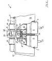
- a control housing 1 for separate arrangement on a cylinder head, not shown, of a valve-controlled internal combustion engine comprises, for a cylinder of the internal combustion engine, openings 2 and 3 arranged in groups for receiving valve tappets 4. Openings 2, 3 are open at both ends 5, 6, specifically both towards the cylinder head and towards a camshaft 7.
- the camshaft 7 is guided in the control housing by means of a bearing 8.
- the split bearing 8 has in its lower bearing part 8 'an essentially over its width "x" sliding bearing bore 9 for a bearing collar 10 of the camshaft 7. This is to achieve a stiff valve train Bearing 8 arranged between the openings 2, 3 for the tappets 4, the tappets 4 interacting with valves assigned to a cylinder (21, 22 in FIG. 2).
- the bearing 8 is in its lower bearing part 8 'with a web 11 between the openings 2 and 3 in the control housing 1 in connection. It is characteristic of this web 11 that it ends at a wall thickness "s" which is smaller than the width "x" of the bearing 8 due to closely spaced openings 2,3 at the bearing side at a predetermined distance "y” from the bearing surface 12 of the slide bearing bore 9.
- a bearing wall 9 ' is thus achieved in the region of the web 11, as a result of which the axial extension of the sliding bearing bore 9 in the lower bearing part 8' is retained over the width "x" of the bearing 8.
- the bearing 8 can thus be supplied with lubricating oil without any problems via bores 13 and 14 in the camshaft.
- the web 11 is connected to an end face 16 of the bearing 8 by means of a continuously running transition 15.
- the transition 15 can be formed, for example, in a control housing 1 designed as a die-cast part.
- a further embodiment of the transition is shown in the opening 3, a step-shaped transition with a flat shoulder 18 adjoining the web 11.
- This paragraph 18 can serve as a machine-fixed stop for a tappet 4 equipped with a hydraulic valve lash compensation element, as a result of which the tappet 4 during operation of the internal combustion engine in the base circle phase with clearance to the base circle 19 of a cam 20 of the camshaft 7 is held. This avoids friction losses in the base circle phase.
- the same elements are given the same reference numerals as in FIG. 1.
- the lubricating oil holes 23, 24 penetrating the bearing wall 9' can be arranged in such a way that a lubricating oil spray jet on the tappet 4 in front of the respective cam 20 of the camshaft 7 is reached.
- the lubricating oil bores 23, 24 penetrating approximately from the center of the bearing wall 12 from the bearing wall 9 ' are connected to a partial circumferential groove 25 in the bearing collar 10 of the camshaft 7 in an oil-carrying manner.
- the part circumferential groove 25 is in turn supplied with lubricating oil from the central bore 13 in the camshaft 7 via the radially directed bore 14.
- the control housing 1 can be provided as a single piece for two gas exchange valves arranged in parallel.
- the control housings provided for one row of valves can be combined to form a one-piece component.
- the individual control housings 1 are connected in a fixed manner to their longitudinal walls 26 and 27 via their lower bearing parts 8 '.
- the control housing 1 is preferably used in a multi-cylinder internal combustion engine with V-shaped and in pairs arranged in a row valves in a cylinder head with right angles to the valves connecting surfaces for the releasably attached control housing assigned to each valve row.
Landscapes
- Engineering & Computer Science (AREA)
- Mechanical Engineering (AREA)
- General Engineering & Computer Science (AREA)
- Chemical & Material Sciences (AREA)
- Combustion & Propulsion (AREA)
- Valve-Gear Or Valve Arrangements (AREA)
- Cylinder Crankcases Of Internal Combustion Engines (AREA)
Priority Applications (1)
| Application Number | Priority Date | Filing Date | Title |
|---|---|---|---|
| AT85113420T ATE39164T1 (de) | 1984-10-29 | 1985-10-23 | Steuergehaeuse fuer zylinderkopf von brennkraftmaschinen, mit zueinander im wesentlichen parallelen gaswechselventilen. |
Applications Claiming Priority (2)
| Application Number | Priority Date | Filing Date | Title |
|---|---|---|---|
| DE3439553 | 1984-10-29 | ||
| DE3439553 | 1984-10-29 |
Publications (2)
| Publication Number | Publication Date |
|---|---|
| EP0180847A1 true EP0180847A1 (fr) | 1986-05-14 |
| EP0180847B1 EP0180847B1 (fr) | 1988-12-07 |
Family
ID=6249017
Family Applications (1)
| Application Number | Title | Priority Date | Filing Date |
|---|---|---|---|
| EP85113420A Expired EP0180847B1 (fr) | 1984-10-29 | 1985-10-23 | Boîtier de commande pour culasse des moteurs à combustion interne avec des soupapes agencées en parallèle |
Country Status (6)
| Country | Link |
|---|---|
| US (1) | US4711203A (fr) |
| EP (1) | EP0180847B1 (fr) |
| JP (1) | JPS62500675A (fr) |
| AT (1) | ATE39164T1 (fr) |
| DE (1) | DE3566708D1 (fr) |
| WO (1) | WO1986002700A1 (fr) |
Families Citing this family (6)
| Publication number | Priority date | Publication date | Assignee | Title |
|---|---|---|---|---|
| US5186129A (en) * | 1992-03-30 | 1993-02-16 | Ford Motor Company | Intermittent oiling system for an internal combustion engine camshaft and valve train |
| JP3311502B2 (ja) * | 1994-07-13 | 2002-08-05 | 本田技研工業株式会社 | 内燃機関のカム摺動面潤滑構造 |
| US5797362A (en) * | 1997-03-24 | 1998-08-25 | Taller; Myron S. | Combustion engine with adjustable cam and lubrication means |
| JP2000120422A (ja) * | 1998-10-12 | 2000-04-25 | Yamaha Motor Co Ltd | エンジンのカム軸潤滑構造 |
| JP3695247B2 (ja) * | 1999-09-28 | 2005-09-14 | スズキ株式会社 | 4サイクルエンジンの潤滑構造 |
| US6460504B1 (en) * | 2001-03-26 | 2002-10-08 | Brunswick Corporation | Compact liquid lubrication circuit within an internal combustion engine |
Citations (4)
| Publication number | Priority date | Publication date | Assignee | Title |
|---|---|---|---|---|
| NL7018294A (fr) * | 1970-12-15 | 1972-06-19 | ||
| DE2342530A1 (de) * | 1972-11-06 | 1974-05-16 | Denzel Kraftfahrzeug Wolfgang | Zylinderkopf fuer brennkraftmaschinen |
| DE3009302A1 (de) * | 1979-03-23 | 1980-09-25 | Denzel Kraftfahrzeug Wolfgang | Zylinderkopf fuer brennkraftmaschinen |
| US4448155A (en) * | 1982-06-03 | 1984-05-15 | Eaton Corporation | Guide for roller cam follower |
Family Cites Families (12)
| Publication number | Priority date | Publication date | Assignee | Title |
|---|---|---|---|---|
| US2209496A (en) * | 1939-02-15 | 1940-07-30 | George Yates | Automatic compression control for engines |
| US2674904A (en) * | 1950-04-22 | 1954-04-13 | Gen Motors Corp | Camshaft |
| US3080704A (en) * | 1956-08-11 | 1963-03-12 | Daimler Benz Ag | Internal combustion engine with exhaust gas turbine |
| DE1221846B (de) * | 1963-07-13 | 1966-07-28 | Volkswagenwerk Ag | Ventilspieleinstellvorrichtung fuer Brennkraftmaschinen |
| DE1476024A1 (de) * | 1964-04-10 | 1970-07-09 | British Aluminium Co Ltd | Zylinder- und Zylinderkopfeinheit fuer Verbrennungskraftmaschinen |
| US3306271A (en) * | 1966-01-19 | 1967-02-28 | Gen Motors Corp | Internal combustion engine with single overhead camshaft and hemispherical combustion chambers |
| US3482555A (en) * | 1968-06-24 | 1969-12-09 | Int Harvester Co | Internal combustion engine valve spring arrangement |
| US3672338A (en) * | 1968-12-27 | 1972-06-27 | Isuzu Motors Ltd | Internal combustion engine with overhead valve mechanism |
| DE2353736C2 (de) * | 1973-10-26 | 1982-09-09 | M.A.N. Maschinenfabrik Augsburg-Nürnberg AG, 8500 Nürnberg | Vorrichtung zum Schmieren der Nocken von Nockenwellen bei Brennkraftmaschinen |
| DE3123527A1 (de) * | 1980-11-27 | 1982-06-24 | Volkswagenwerk Ag, 3180 Wolfsburg | "hubkolben-brennkraftmaschine mit oelraeumen zur kuehlung" |
| FR2540553A1 (fr) * | 1983-02-03 | 1984-08-10 | Renault | Dispositif de commande a came, notamment pour soupapes de moteurs a combustion interne |
| JPS59158305A (ja) * | 1983-02-26 | 1984-09-07 | Mazda Motor Corp | エンジンのバルブタイミング制御装置 |
-
1985
- 1985-10-05 JP JP60504762A patent/JPS62500675A/ja active Granted
- 1985-10-05 US US06/874,163 patent/US4711203A/en not_active Expired - Lifetime
- 1985-10-05 WO PCT/EP1985/000521 patent/WO1986002700A1/fr not_active Ceased
- 1985-10-23 EP EP85113420A patent/EP0180847B1/fr not_active Expired
- 1985-10-23 AT AT85113420T patent/ATE39164T1/de not_active IP Right Cessation
- 1985-10-23 DE DE8585113420T patent/DE3566708D1/de not_active Expired
Patent Citations (4)
| Publication number | Priority date | Publication date | Assignee | Title |
|---|---|---|---|---|
| NL7018294A (fr) * | 1970-12-15 | 1972-06-19 | ||
| DE2342530A1 (de) * | 1972-11-06 | 1974-05-16 | Denzel Kraftfahrzeug Wolfgang | Zylinderkopf fuer brennkraftmaschinen |
| DE3009302A1 (de) * | 1979-03-23 | 1980-09-25 | Denzel Kraftfahrzeug Wolfgang | Zylinderkopf fuer brennkraftmaschinen |
| US4448155A (en) * | 1982-06-03 | 1984-05-15 | Eaton Corporation | Guide for roller cam follower |
Also Published As
| Publication number | Publication date |
|---|---|
| DE3566708D1 (en) | 1989-01-12 |
| WO1986002700A1 (fr) | 1986-05-09 |
| JPH0447123B2 (fr) | 1992-08-03 |
| US4711203A (en) | 1987-12-08 |
| ATE39164T1 (de) | 1988-12-15 |
| EP0180847B1 (fr) | 1988-12-07 |
| JPS62500675A (ja) | 1987-03-19 |
Similar Documents
| Publication | Publication Date | Title |
|---|---|---|
| DE3436426C2 (fr) | ||
| DE4326159C5 (de) | Wassergekühlte mehrzylindrige Brennkraftmaschine mit V-förmig angeordneten Zylinderreihen | |
| DE69101915T2 (de) | Verbundene rotierende und hin- und hergehende bewegung. | |
| DE3634877C2 (fr) | ||
| DE3515850A1 (de) | Ventilbetaetigungseinrichtung fuer eine obengesteuerte brennkraftmaschine | |
| DE69027032T2 (de) | Nockenwellenanordnung für eine Mehrventil-Brennkraftmaschine | |
| DE69612087T2 (de) | Kipphebelvorrichtung für brennkraftmaschine | |
| EP0806552B1 (fr) | Culasse pour moteur à combustion interne | |
| AT393297B (de) | Zylinderkopf fuer brennkraftmaschinen | |
| EP0688946A1 (fr) | Agencement d'une culasse d'un moteur à combustion interne | |
| DE69414557T2 (de) | Zylinderkopfanordnung für eine Mehrventil-Brennkraftmaschine mit obenliegender Nockenwelle | |
| DE10000750A1 (de) | Mehrzylindermotor für ein Motorrad | |
| EP0180847B1 (fr) | Boîtier de commande pour culasse des moteurs à combustion interne avec des soupapes agencées en parallèle | |
| EP0806562B1 (fr) | Culasse pour moteur à combustion interne | |
| EP0845582B1 (fr) | Commande de soupape pour un moteur à combustion interne équipé de soupapes à levée pour le transfert de charge | |
| DE69411413T2 (de) | Brennkraftmaschine | |
| DE19723342C1 (de) | Zylinderkopf und Gießkern zur Herstellung von Ölkanälen | |
| AT402321B (de) | Zylinderkopf für brennkraftmaschinen | |
| EP0774575B1 (fr) | Culasse moulée d'un moteur à combustion interne multicylindre | |
| DE102004034912B4 (de) | Zylinderkopfstruktur eines Motors | |
| DE69315321T2 (de) | Brennkraftmaschine | |
| DE69905809T2 (de) | Schmierungssystem für einen Kolbenverdichter einer aufgeladenen Brennkraftmaschine | |
| DE69103613T2 (de) | Ventilstössel. | |
| AT392823B (de) | Brennkraftmaschine | |
| EP0353577A2 (fr) | Culasse pour moteur à combustion interne |
Legal Events
| Date | Code | Title | Description |
|---|---|---|---|
| PUAI | Public reference made under article 153(3) epc to a published international application that has entered the european phase |
Free format text: ORIGINAL CODE: 0009012 |
|
| AK | Designated contracting states |
Kind code of ref document: A1 Designated state(s): AT DE FR GB IT SE |
|
| 17P | Request for examination filed |
Effective date: 19860614 |
|
| 17Q | First examination report despatched |
Effective date: 19870325 |
|
| GRAA | (expected) grant |
Free format text: ORIGINAL CODE: 0009210 |
|
| AK | Designated contracting states |
Kind code of ref document: B1 Designated state(s): AT DE FR GB IT SE |
|
| REF | Corresponds to: |
Ref document number: 39164 Country of ref document: AT Date of ref document: 19881215 Kind code of ref document: T |
|
| REF | Corresponds to: |
Ref document number: 3566708 Country of ref document: DE Date of ref document: 19890112 |
|
| ET | Fr: translation filed | ||
| ITF | It: translation for a ep patent filed | ||
| GBT | Gb: translation of ep patent filed (gb section 77(6)(a)/1977) | ||
| PLBE | No opposition filed within time limit |
Free format text: ORIGINAL CODE: 0009261 |
|
| STAA | Information on the status of an ep patent application or granted ep patent |
Free format text: STATUS: NO OPPOSITION FILED WITHIN TIME LIMIT |
|
| 26N | No opposition filed | ||
| ITTA | It: last paid annual fee | ||
| EAL | Se: european patent in force in sweden |
Ref document number: 85113420.5 |
|
| REG | Reference to a national code |
Ref country code: GB Ref legal event code: IF02 |
|
| PGFP | Annual fee paid to national office [announced via postgrant information from national office to epo] |
Ref country code: GB Payment date: 20041021 Year of fee payment: 20 |
|
| PGFP | Annual fee paid to national office [announced via postgrant information from national office to epo] |
Ref country code: AT Payment date: 20041025 Year of fee payment: 20 |
|
| PGFP | Annual fee paid to national office [announced via postgrant information from national office to epo] |
Ref country code: SE Payment date: 20041027 Year of fee payment: 20 |
|
| PGFP | Annual fee paid to national office [announced via postgrant information from national office to epo] |
Ref country code: FR Payment date: 20041028 Year of fee payment: 20 |
|
| PGFP | Annual fee paid to national office [announced via postgrant information from national office to epo] |
Ref country code: DE Payment date: 20041124 Year of fee payment: 20 |
|
| PG25 | Lapsed in a contracting state [announced via postgrant information from national office to epo] |
Ref country code: GB Free format text: LAPSE BECAUSE OF EXPIRATION OF PROTECTION Effective date: 20051022 |
|
| REG | Reference to a national code |
Ref country code: GB Ref legal event code: PE20 |
|
| EUG | Se: european patent has lapsed |