EP0688946A1 - Agencement d'une culasse d'un moteur à combustion interne - Google Patents
Agencement d'une culasse d'un moteur à combustion interne Download PDFInfo
- Publication number
- EP0688946A1 EP0688946A1 EP95107276A EP95107276A EP0688946A1 EP 0688946 A1 EP0688946 A1 EP 0688946A1 EP 95107276 A EP95107276 A EP 95107276A EP 95107276 A EP95107276 A EP 95107276A EP 0688946 A1 EP0688946 A1 EP 0688946A1
- Authority
- EP
- European Patent Office
- Prior art keywords
- cylinder head
- housing
- cylinder
- bearing block
- head arrangement
- Prior art date
- Legal status (The legal status is an assumption and is not a legal conclusion. Google has not performed a legal analysis and makes no representation as to the accuracy of the status listed.)
- Granted
Links
Images

Classifications
-
- F—MECHANICAL ENGINEERING; LIGHTING; HEATING; WEAPONS; BLASTING
- F02—COMBUSTION ENGINES; HOT-GAS OR COMBUSTION-PRODUCT ENGINE PLANTS
- F02F—CYLINDERS, PISTONS OR CASINGS, FOR COMBUSTION ENGINES; ARRANGEMENTS OF SEALINGS IN COMBUSTION ENGINES
- F02F1/00—Cylinders; Cylinder heads
-
- F—MECHANICAL ENGINEERING; LIGHTING; HEATING; WEAPONS; BLASTING
- F02—COMBUSTION ENGINES; HOT-GAS OR COMBUSTION-PRODUCT ENGINE PLANTS
- F02F—CYLINDERS, PISTONS OR CASINGS, FOR COMBUSTION ENGINES; ARRANGEMENTS OF SEALINGS IN COMBUSTION ENGINES
- F02F1/00—Cylinders; Cylinder heads
- F02F1/24—Cylinder heads
- F02F1/42—Shape or arrangement of intake or exhaust channels in cylinder heads
- F02F1/4214—Shape or arrangement of intake or exhaust channels in cylinder heads specially adapted for four or more valves per cylinder
-
- F—MECHANICAL ENGINEERING; LIGHTING; HEATING; WEAPONS; BLASTING
- F02—COMBUSTION ENGINES; HOT-GAS OR COMBUSTION-PRODUCT ENGINE PLANTS
- F02F—CYLINDERS, PISTONS OR CASINGS, FOR COMBUSTION ENGINES; ARRANGEMENTS OF SEALINGS IN COMBUSTION ENGINES
- F02F7/00—Casings, e.g. crankcases
- F02F7/006—Camshaft or pushrod housings
-
- F—MECHANICAL ENGINEERING; LIGHTING; HEATING; WEAPONS; BLASTING
- F02—COMBUSTION ENGINES; HOT-GAS OR COMBUSTION-PRODUCT ENGINE PLANTS
- F02B—INTERNAL-COMBUSTION PISTON ENGINES; COMBUSTION ENGINES IN GENERAL
- F02B1/00—Engines characterised by fuel-air mixture compression
- F02B1/02—Engines characterised by fuel-air mixture compression with positive ignition
- F02B1/04—Engines characterised by fuel-air mixture compression with positive ignition with fuel-air mixture admission into cylinder
-
- F—MECHANICAL ENGINEERING; LIGHTING; HEATING; WEAPONS; BLASTING
- F02—COMBUSTION ENGINES; HOT-GAS OR COMBUSTION-PRODUCT ENGINE PLANTS
- F02B—INTERNAL-COMBUSTION PISTON ENGINES; COMBUSTION ENGINES IN GENERAL
- F02B2275/00—Other engines, components or details, not provided for in other groups of this subclass
- F02B2275/18—DOHC [Double overhead camshaft]
-
- F—MECHANICAL ENGINEERING; LIGHTING; HEATING; WEAPONS; BLASTING
- F02—COMBUSTION ENGINES; HOT-GAS OR COMBUSTION-PRODUCT ENGINE PLANTS
- F02B—INTERNAL-COMBUSTION PISTON ENGINES; COMBUSTION ENGINES IN GENERAL
- F02B3/00—Engines characterised by air compression and subsequent fuel addition
- F02B3/06—Engines characterised by air compression and subsequent fuel addition with compression ignition
-
- F—MECHANICAL ENGINEERING; LIGHTING; HEATING; WEAPONS; BLASTING
- F02—COMBUSTION ENGINES; HOT-GAS OR COMBUSTION-PRODUCT ENGINE PLANTS
- F02F—CYLINDERS, PISTONS OR CASINGS, FOR COMBUSTION ENGINES; ARRANGEMENTS OF SEALINGS IN COMBUSTION ENGINES
- F02F1/00—Cylinders; Cylinder heads
- F02F1/02—Cylinders; Cylinder heads having cooling means
- F02F1/10—Cylinders; Cylinder heads having cooling means for liquid cooling
- F02F2001/104—Cylinders; Cylinder heads having cooling means for liquid cooling using an open deck, i.e. the water jacket is open at the block top face
-
- F—MECHANICAL ENGINEERING; LIGHTING; HEATING; WEAPONS; BLASTING
- F02—COMBUSTION ENGINES; HOT-GAS OR COMBUSTION-PRODUCT ENGINE PLANTS
- F02F—CYLINDERS, PISTONS OR CASINGS, FOR COMBUSTION ENGINES; ARRANGEMENTS OF SEALINGS IN COMBUSTION ENGINES
- F02F1/00—Cylinders; Cylinder heads
- F02F1/24—Cylinder heads
- F02F2001/244—Arrangement of valve stems in cylinder heads
- F02F2001/245—Arrangement of valve stems in cylinder heads the valve stems being orientated at an angle with the cylinder axis
Definitions
- the invention relates to a cylinder head arrangement according to the preamble of patent claim 1.
- DE 41 16 942 C1 shows a generic cylinder head arrangement in which a basic housing is placed on a cylinder block and screwed to it.
- the basic housing has raised outer walls on which a hood-like cover is placed.
- a bucket tappet housing is arranged at a distance from the external walls, which is screwed to the basic housing.
- the bucket tappet housing is made of several parts and has in a basic element the guides of the valve cups and the lower half of the bearing block for mounting the camshafts. Separate upper bearing block halves are placed on these lower bearing block halves and screwed to the lower parts.
- a cylinder head is known for the engine type B6304, in which the basic housing placed on the cylinder block is formed in one piece with a tappet guide and the lower parts of camshaft bearings. A cylinder head cover carrying the upper bearing parts is placed on this basic housing.
- the invention is therefore based on the object of improving a generic cylinder head arrangement in such a way that both a high-strength material structure, in particular of the basic housing, can be achieved, that the entire cylinder head arrangement has high overall rigidity and is easy to manufacture and assemble.
- the camshafts are supported between the basic housing and the cylinder head cover and the bucket tappet housing is made in one piece and is only used to guide the valve cups, simple-to-manufacture, easy-to-assemble components result which have a high overall rigidity in the assembled state.
- the three individual elements of the basic housing, bucket tappet guide and cylinder head cover can be assembled using a small number of screw connections. This also results in a very compact design of the cylinder head arrangement, which has a relatively low overall height and, above all, a small overall width for a cylinder head with overhead camshafts and bucket tappets.
- the cylinder head cover and the tappet housing can be manufactured, for example, as die-cast components.
- the basic housing of the cylinder head arrangement can advantageously be created in permanent mold casting, with only the channels required for the water supply (in the case of a water-cooled cylinder head) having to be created by molding sand or similar casting or molding techniques.
- this three-part design of the cylinder head arrangement results in only one outside separating plane to be sealed, so that oil leakage can be prevented with comparatively simple means.
- the overall rigidity of the cylinder head assembly in the assembled state can advantageously be increased if the bearing blocks are each connected to the adjacent outer walls, i. H. when the upper half of the bearing block is connected to the respectively adjacent outer wall of the cylinder head cover and the lower half of the bearing block is connected to the respectively adjacent outer wall of the basic housing.
- the assembly of the cylinder head arrangement can be considerably simplified if the screw connection between the cylinder head cover and the basic housing takes place at least in the area of the cylinder bores through the screw connection of the bearing block halves. This results in a significant reduction in the number of screw connections. At the same time, the overall width of the cylinder head arrangement is reduced, since the screw connections required for this connection are no longer required outside.
- An inexpensive, high-strength screw connection between the cylinder head arrangement and the cylinder block is obtained if four cylinder screws are provided for each cylinder, comprising the cylinder bore in a rectangular arrangement. It is advantageous if, with sufficient installation space between the respective cylinders, as can be found, for example, in engines in boxer arrangements, a bearing block is arranged between two cylinder screws of the adjacent cylinder bores.
- camshaft bearing are greatly simplified if the bearing is on one end of the cylinder head arrangement the respective camshaft is carried out by a single bearing block. These individual bearing blocks allow the camshafts to be pressed down against the action of the valve springs. It is particularly advantageous for the design and manufacture of the camshaft bearing if the axial guidance of the camshafts takes place through these individual bearing blocks.
- the arrangement of the individual bearing blocks is advantageously carried out in the area of the chain boxes required for driving the camshafts.
- the bores of the camshaft bearing can then be made from the opposite end face of the cylinder head arrangement, so that these openings in the end face can simultaneously serve as an engagement for a tool for depressing the camshafts when assembling the camshafts.
- connection between the bucket tappet housing and the basic housing advantageously takes place in a parting plane into which channels for the oil guide can be cast in a manner which is favorable in terms of production technology. This significantly reduces the amount of drilling required for the oil guide. Via these cast oil channels, the valve cups and the camshaft can be lubricated with a few holes.
- Both the manufacture and the sealing of the cylinder head arrangement can be improved if the shaft opening into the combustion chamber for receiving a spark plug or an injection device is extended and sealed by a sleeve which is inserted between the tappet housing and the cylinder head arrangement.
- This sleeve can be inserted and sealed in a ring-shaped extension in the tappet housing in a simple and easy-to-assemble manner.
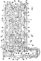
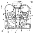
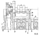
- An internal combustion engine has a cylinder head arrangement placed on a cylinder block 1, the housing of which is composed of three housing components, a basic housing 2, a tappet housing 3 and a cylinder head cover 4.
- the internal combustion engine is in the form of a cylinder bank of a six-cylinder boxer engine with four valves each Cylinder and two overhead camshafts shown.
- This internal combustion engine consequently has three cylinder bores 5 per cylinder bank, which are designated as left, middle and right cylinders or corresponding cylinder bores 5 according to the type of representation selected in FIG. 1.
- Each of these cylinder bores 5 is controlled via four disk springs (two inlet valves, two outlet valves), which are guided in valve guides 6 and are not shown in detail, and corresponding gas exchange channels 7.
- the gas exchange channels 7 and valve guides 6 are integrated in a basic block 8 of the basic housing 2, to which a chain case 9 is connected at the end. This serves to accommodate drive means (not shown) for the control drive.
- a chain case 9 is connected at the end.
- This serves to accommodate drive means (not shown) for the control drive.
- outer walls 10, 11 and 12 which are raised up to an internal support surface 13 up to a parting plane T-T.
- the chain case 9 is enclosed by outer walls 14, which also extend to the parting plane T-T and adjoin the walls 10 and 12 of the base block 8.
- three shafts 15 are formed, each of which emanate from the support surface 13 and into one of the three cylinder bores 5 lead.
- the axes of the three shafts 15 lie in a central longitudinal plane M and each serve to receive a spark plug 16. However, they can also be used, in particular in the case of diesel engines, to accommodate injection devices or glow plugs.
- Each of these shafts 15 is surrounded by an annular cast-in recess 17, which is part of the oil guide of the cylinder head.
- the annular recess 17 in the region of the left cylinder is connected to a likewise cast-in longitudinal groove 18, which is connected in a manner not shown to the oil supply to the cylinder head arrangement. This longitudinal groove 18 runs approximately parallel to the central longitudinal plane M.
- the annular depressions in the area of the middle and right cylinders are connected to one another by a further cast-in longitudinal groove 19, which is also connected to the oil supply to the cylinder head arrangement and runs approximately parallel to the central longitudinal plane M.
- the annular depressions 17 and the longitudinal grooves 18 and 19 are each surrounded by a sealing web 20, the sealing surface of which is part of the support surface 13.
- the annular depressions 17 each lie within a rectangle formed by the passage openings of the valve guides 6 in the base 13, the shorter sides of which are parallel to the central longitudinal plane M.
- the valve guides 6 are each inclined against this plane and arranged in two rows.
- the basic housing 2 is screwed to the cylinder block 1 in two rows, i.e. the screw connections are each in a plane E1 or E2 parallel to the central longitudinal plane M.
- the screw connections 21 between the basic housing 2 and the cylinder block 1 and the further screw connections explained in more detail below are shown here for the sake of clarity only by their bores.
- Four screw connections 21 are provided for each cylinder bore 5, the connecting lines of which form a rectangle which includes the valve guides 6.
- the rectangle formed by the four screw connections 21 per cylinder has its shorter sides parallel to the central longitudinal plane M.
- each camshaft or valve row In the basic block 8 of the basic housing 2, four lower bearing block halves 22 are also arranged for each camshaft or valve row. Each lie the lower half of the bearing block of the two rows of valves opposite each other.
- a first pair of bearing blocks 22 is arranged in the area of the chain case 9, a second pair of bearing blocks 22 is located in the area of the opposite outer or end wall 11 and two further pairs of bearing block halves 22 are located between the left and middle cylinders or between the middle and right Cylinder.
- These two pairs of bearing block halves 22 are each arranged between two adjacent screw connections 21 of the adjacent cylinder bores 5.
- These holes 23 are arranged so that the camshaft to be inserted is between them.
- four rows or levels of screw connections or bores 23 are formed which, in the orientation of the basic housing 2 shown in FIG. 1, are designated B1 to B4 from top to bottom.
- the bore level B1 is above the level E1 of the screw connections 21 and the bore level B2 is below this level. Both bore levels B1 and B2 lie above the central level M.
- the bore levels of the lower row of bearing block halves are designated as B3 and B4, the bore level B3 is above and the bore level B4 is below the level E2 of the screw connections 21.
- the screw connections 24 of the bucket tappet housing 2 lie in two planes T1 and T2 parallel to the central plane M.
- the upper plane T1 lies between the bore plane B1 facing the outer wall 10 and the plane E1 of the screw connections 21, the lower plane T2 lies between the lower plane E2 of the screw connections 21 and of the bore plane B4 of the bearing block halves 22 facing the outer wall 12.
- a third row of screw connections 25 for the bucket tappet housing 3 lies in the central longitudinal plane M. Additional screw connections 26 are provided in the area of the sealing webs 20 for better sealing of the cast oil channels.
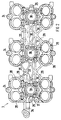
- the bucket tappet housing 2 with its base surface 27 is placed on the support surface 13 of the base housing 2 such that the bores or screw connections 24 to 26 continue accordingly.
- the tappet housing 2 comprises 5 four tappet guides 28 per cylinder bore, which are aligned with the respective axes of the valve guides.
- the four bucket tappet guides 28 are connected to each other.
- Each of this group of four cup tappet guides 28 is connected via webs 29 to the adjacent group of cup tappet guides 28, so that the entire cup tappet housing is formed in one piece.
- a bore 30 is provided which is aligned with the shaft 15.
- Each of these bores is surrounded on the top of the tappet housing 2 by an annular extension 31.
- annular groove 32 is formed for each bore 30, which together with the annular recess 17 forms an oil channel in the support surface 13.
- the annular groove 32 in the area of the left cylinder bore is connected to a longitudinal groove 33, which is arranged in a longitudinal web 34 and forms an oil channel with the longitudinal groove 18 in the basic housing 2.
- the annular grooves 32 in the region of the middle and right cylinder bore are also connected to one another via a longitudinal groove 34 which interacts with the corresponding longitudinal groove 19 in the basic housing 2 and is cast into a longitudinal web 36.
- the cup tappet guides are supplied with oil via oblique bores 46 which open into the annular groove 32.
- the cylinder head arrangement is closed by a cylinder head cover 4, which is placed on the outer walls 10 to 12 and 14 of the basic housing 2 in the area of the parting plane TT and covers the tappet housing 3.
- the cylinder head cover contains three pairs of upper bearing block halves 37, each of which cooperate with the lower bearing block halves 22 arranged between the left and middle cylinders, the middle and right cylinders and in the region of the right front and outer wall 11.
- These upper bracket halves 37 each go from one Outer wall of the cylinder head cover 24 or are integrally connected to this.
- the screw connection between the base housing 2 and the cylinder head cover 4 takes place in the area of the base block 8 by means of the screw connection 23 of the bearing block halves.
- Additional screw connections 38 are provided in the area of the outer walls 14 only in the area of the chain case 9.
- three holes 39 are arranged, each aligned with one of the shafts 15.
- sleeves 40 are inserted, which extend into the annular extension 31 of the tappet housing 3 and are sealed there and in the area of the bore 39 by sealing rings 41 and 42, respectively.
- These sleeves 40 extend or seal the shaft 15 or the bore 30 against the interior, which is formed by the basic housing 2 and the cylinder head cover 4.
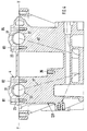
- the camshafts 43 are supported in the area of the chain case 9 by the two lower bearing block halves 22, onto which separate individual bearing block upper parts 44 are placed. These separate upper bearing block parts 44 are wider (viewed in the axial direction) than the corresponding lower half of the bearing block 22 and take over the axial guidance of the camshaft. This means that only one separate upper bearing part needs to be machined for the axial guidance per camshaft. Due to the separate top bracket parts, the camshafts are pressed down on the chain box side against the action of the valve springs (not shown).
- mounting bores 45 are made, which serve on the one hand for machining the bearing bores and on the other hand for depressing the camshafts during assembly or create the necessary space.
Landscapes
- Engineering & Computer Science (AREA)
- Chemical & Material Sciences (AREA)
- Combustion & Propulsion (AREA)
- Mechanical Engineering (AREA)
- General Engineering & Computer Science (AREA)
- Cylinder Crankcases Of Internal Combustion Engines (AREA)
- Valve-Gear Or Valve Arrangements (AREA)
- Lubrication Of Internal Combustion Engines (AREA)
Applications Claiming Priority (2)
| Application Number | Priority Date | Filing Date | Title |
|---|---|---|---|
| DE4421057 | 1994-06-16 | ||
| DE4421057A DE4421057C1 (de) | 1994-06-16 | 1994-06-16 | Zylinderkopfanordnung einer Brennkraftmaschine |
Publications (2)
| Publication Number | Publication Date |
|---|---|
| EP0688946A1 true EP0688946A1 (fr) | 1995-12-27 |
| EP0688946B1 EP0688946B1 (fr) | 1998-09-23 |
Family
ID=6520744
Family Applications (1)
| Application Number | Title | Priority Date | Filing Date |
|---|---|---|---|
| EP95107276A Expired - Lifetime EP0688946B1 (fr) | 1994-06-16 | 1995-05-13 | Agencement d'une culasse d'un moteur à combustion interne |
Country Status (5)
| Country | Link |
|---|---|
| US (1) | US5609129A (fr) |
| EP (1) | EP0688946B1 (fr) |
| JP (1) | JP3648285B2 (fr) |
| KR (1) | KR100350193B1 (fr) |
| DE (2) | DE4421057C1 (fr) |
Cited By (1)
| Publication number | Priority date | Publication date | Assignee | Title |
|---|---|---|---|---|
| FR2749345A1 (fr) * | 1996-05-28 | 1997-12-05 | Daimler Benz Ag | Guide pour poussoir en godet d'une soupape de moteur a combustion interne |
Families Citing this family (15)
| Publication number | Priority date | Publication date | Assignee | Title |
|---|---|---|---|---|
| DE19548088C1 (de) * | 1995-12-21 | 1997-07-17 | Daimler Benz Ag | Zylinderkopf für eine Brennkraftmaschine |
| DE19618401C1 (de) * | 1996-05-08 | 1997-07-03 | Porsche Ag | Zylinderkopfanordnung einer Brennkraftmaschine |
| DE19619183C1 (de) * | 1996-05-11 | 1997-07-03 | Porsche Ag | Zylinderkopfanordnung einer Brennkraftmaschine |
| DE19712658A1 (de) * | 1997-03-26 | 1998-10-01 | Schaeffler Waelzlager Ohg | Zylinderkopf einer Hubkolbenbrennkraftmaschine |
| JPH10331709A (ja) * | 1997-05-29 | 1998-12-15 | Suzuki Motor Corp | 内燃機関のシリンダヘッド構造 |
| DE19728947C2 (de) * | 1997-07-07 | 2001-03-15 | Audi Ag | Brennkraftmaschine mit einem Zylinderkopf |
| DE19833199B4 (de) * | 1998-07-23 | 2006-09-28 | Audi Ag | Zylinderkopfhaube einer Brennkraftmaschine |
| DE19928838C1 (de) * | 1999-06-24 | 2001-02-15 | Otmar Gaehrken | Zylinderkopf |
| DE102004006343B4 (de) * | 2004-02-10 | 2017-09-14 | Bayerische Motoren Werke Aktiengesellschaft | Zylinderkopf |
| JP4191648B2 (ja) * | 2004-05-21 | 2008-12-03 | 本田技研工業株式会社 | エンジン |
| AT500411B8 (de) * | 2004-11-25 | 2007-02-15 | Avl List Gmbh | Zylinderkopfanordnung für eine brennkraftmaschine |
| US8820277B2 (en) * | 2011-03-08 | 2014-09-02 | GM Global Technology Operations LLC | Engine assembly including cylinder head oil gallery |
| EP2746559B1 (fr) * | 2012-12-21 | 2016-06-29 | Caterpillar Motoren GmbH & Co. KG | Tête de cylindre et configuration de bloc de moteur |
| GB201603445D0 (en) * | 2016-02-29 | 2016-04-13 | Delphi Internat Operations Luxembourg S À R L | Fuel rail clamping arrangement |
| US12258929B1 (en) * | 2022-08-05 | 2025-03-25 | Paul J. Gremillion | Method and apparatus for sealing a spark plug well |
Citations (5)
| Publication number | Priority date | Publication date | Assignee | Title |
|---|---|---|---|---|
| DE3209901C1 (de) * | 1982-03-18 | 1983-10-27 | Audi Nsu Auto Union Ag, 7107 Neckarsulm | Einteiliger Zylinderkopf für eine Hubkolben-Brennkraftmaschine |
| DE3641129C1 (de) * | 1986-12-02 | 1987-07-30 | Daimler Benz Ag | Vorrichtung zur Lagerung von zwei Nockenwellen im Zylinderkopf einer mehrzylindrigen Reihenbrennkraftmaschine |
| US4805563A (en) * | 1986-05-27 | 1989-02-21 | Mazda Motor Corporation | Block construction of engine |
| US4944263A (en) * | 1988-11-16 | 1990-07-31 | Nissan Motor Co., Ltd. | Cylinder head of DOHC engine |
| US5150675A (en) * | 1990-11-29 | 1992-09-29 | Mitsubishi Jidosha Kogyo Kabushiki Kaisha | Cylinder head assembly for use in internal combustion engine |
Family Cites Families (7)
| Publication number | Priority date | Publication date | Assignee | Title |
|---|---|---|---|---|
| US4660529A (en) * | 1981-04-22 | 1987-04-28 | Yamaha Hatsudoki Kabushiki Kaisha | Four-cycle engine |
| JPH0646005B2 (ja) * | 1984-06-12 | 1994-06-15 | ヤマハ発動機株式会社 | 動弁用カム軸の軸受構造 |
| DE3943727C2 (de) * | 1989-12-11 | 1995-07-13 | Porsche Ag | Zylinderkopf einer Brennkraftmaschine |
| US5101777A (en) * | 1990-02-20 | 1992-04-07 | Yamaha Hatsudoki Kabushiki Kaisha | Automobile engine structure |
| DE4116942C1 (en) * | 1991-05-24 | 1992-05-27 | Mercedes-Benz Aktiengesellschaft, 7000 Stuttgart, De | Cylinder head for multicylinder IC engine - has accessory cover bolts with oil bores for guiding oil to bearing points and valve tappets |
| DE4116944C2 (de) * | 1991-05-24 | 1997-05-22 | Daimler Benz Ag | Zylinderkopf für eine mehrzylindrige Brennkraftmaschine |
| DE4324791A1 (de) * | 1993-07-23 | 1995-01-26 | Porsche Ag | Zylinderkopfanordnung einer Brennkraftmaschine |
-
1994
- 1994-06-16 DE DE4421057A patent/DE4421057C1/de not_active Expired - Fee Related
-
1995
- 1995-05-13 DE DE59503664T patent/DE59503664D1/de not_active Expired - Fee Related
- 1995-05-13 EP EP95107276A patent/EP0688946B1/fr not_active Expired - Lifetime
- 1995-06-09 JP JP14358095A patent/JP3648285B2/ja not_active Expired - Fee Related
- 1995-06-15 US US08/490,575 patent/US5609129A/en not_active Expired - Fee Related
- 1995-06-16 KR KR1019950015968A patent/KR100350193B1/ko not_active Expired - Fee Related
Patent Citations (5)
| Publication number | Priority date | Publication date | Assignee | Title |
|---|---|---|---|---|
| DE3209901C1 (de) * | 1982-03-18 | 1983-10-27 | Audi Nsu Auto Union Ag, 7107 Neckarsulm | Einteiliger Zylinderkopf für eine Hubkolben-Brennkraftmaschine |
| US4805563A (en) * | 1986-05-27 | 1989-02-21 | Mazda Motor Corporation | Block construction of engine |
| DE3641129C1 (de) * | 1986-12-02 | 1987-07-30 | Daimler Benz Ag | Vorrichtung zur Lagerung von zwei Nockenwellen im Zylinderkopf einer mehrzylindrigen Reihenbrennkraftmaschine |
| US4944263A (en) * | 1988-11-16 | 1990-07-31 | Nissan Motor Co., Ltd. | Cylinder head of DOHC engine |
| US5150675A (en) * | 1990-11-29 | 1992-09-29 | Mitsubishi Jidosha Kogyo Kabushiki Kaisha | Cylinder head assembly for use in internal combustion engine |
Cited By (1)
| Publication number | Priority date | Publication date | Assignee | Title |
|---|---|---|---|---|
| FR2749345A1 (fr) * | 1996-05-28 | 1997-12-05 | Daimler Benz Ag | Guide pour poussoir en godet d'une soupape de moteur a combustion interne |
Also Published As
| Publication number | Publication date |
|---|---|
| KR960001452A (ko) | 1996-01-25 |
| KR100350193B1 (ko) | 2002-12-18 |
| EP0688946B1 (fr) | 1998-09-23 |
| DE59503664D1 (de) | 1998-10-29 |
| DE4421057C1 (de) | 1995-09-14 |
| JPH0849595A (ja) | 1996-02-20 |
| JP3648285B2 (ja) | 2005-05-18 |
| US5609129A (en) | 1997-03-11 |
Similar Documents
| Publication | Publication Date | Title |
|---|---|---|
| EP0436779B1 (fr) | Culasse pour moteur à combustion interne | |
| EP1573190B1 (fr) | Culasse de moteur a combustion interne a baguette de palier d'arbre a cames | |
| EP0635631B1 (fr) | Agencement d'une culasse d'un moteur à combustion interne | |
| DE4421057C1 (de) | Zylinderkopfanordnung einer Brennkraftmaschine | |
| DE3641129C1 (de) | Vorrichtung zur Lagerung von zwei Nockenwellen im Zylinderkopf einer mehrzylindrigen Reihenbrennkraftmaschine | |
| DE2420051A1 (de) | Zylinderkopfblock | |
| DE3515850A1 (de) | Ventilbetaetigungseinrichtung fuer eine obengesteuerte brennkraftmaschine | |
| EP0514643B1 (fr) | Culasse pour un moteur à combustion interne à plusieurs cylindres | |
| DE3543443C2 (fr) | ||
| AT402325B (de) | Zylinderkopf einer flüssigkeitsgekühlten brennkraftmaschine mit in reihe angeordneten zylindern | |
| EP0806552B1 (fr) | Culasse pour moteur à combustion interne | |
| DE3601274A1 (de) | Brennkraftmaschine | |
| EP0838586B1 (fr) | Culasse pour un machine à combustion interne à plusieurs cylindres | |
| EP0806562B1 (fr) | Culasse pour moteur à combustion interne | |
| DE69519326T2 (de) | Brennkraftmaschine | |
| DE19723342C1 (de) | Zylinderkopf und Gießkern zur Herstellung von Ölkanälen | |
| DE4119594C2 (de) | Flüssigkeitsgekühlter Leichtmetall-Zylinderkopf | |
| EP0515925A1 (fr) | Culasse pour moteur à combustion | |
| DE4417309A1 (de) | Hubkolben-Brennkraftmaschine mit Verdichtungssteuerung | |
| DE3243013C2 (fr) | ||
| DE3604667A1 (de) | Gegossener zylinderkopf fuer eine mehrzylindrige reihen-brennkraftmaschine | |
| DE2943560C2 (de) | Vorrichtung für einen Verbrennungsmotor | |
| DE4235103B4 (de) | Nockenwellen-Ventilsteuerung für eine Brennkraftmaschine mit zwei Zylinderreihen | |
| EP1101028B1 (fr) | Culasse pour moteur a combustion interne a piston | |
| EP0353577B1 (fr) | Culasse pour moteur à combustion interne |
Legal Events
| Date | Code | Title | Description |
|---|---|---|---|
| PUAI | Public reference made under article 153(3) epc to a published international application that has entered the european phase |
Free format text: ORIGINAL CODE: 0009012 |
|
| AK | Designated contracting states |
Kind code of ref document: A1 Designated state(s): DE FR GB IT SE |
|
| 17P | Request for examination filed |
Effective date: 19960411 |
|
| GRAG | Despatch of communication of intention to grant |
Free format text: ORIGINAL CODE: EPIDOS AGRA |
|
| GRAG | Despatch of communication of intention to grant |
Free format text: ORIGINAL CODE: EPIDOS AGRA |
|
| GRAH | Despatch of communication of intention to grant a patent |
Free format text: ORIGINAL CODE: EPIDOS IGRA |
|
| 17Q | First examination report despatched |
Effective date: 19980317 |
|
| ITF | It: translation for a ep patent filed | ||
| GRAH | Despatch of communication of intention to grant a patent |
Free format text: ORIGINAL CODE: EPIDOS IGRA |
|
| GRAA | (expected) grant |
Free format text: ORIGINAL CODE: 0009210 |
|
| AK | Designated contracting states |
Kind code of ref document: B1 Designated state(s): DE FR GB IT SE |
|
| REF | Corresponds to: |
Ref document number: 59503664 Country of ref document: DE Date of ref document: 19981029 |
|
| GBT | Gb: translation of ep patent filed (gb section 77(6)(a)/1977) |
Effective date: 19981016 |
|
| ET | Fr: translation filed | ||
| PLBE | No opposition filed within time limit |
Free format text: ORIGINAL CODE: 0009261 |
|
| STAA | Information on the status of an ep patent application or granted ep patent |
Free format text: STATUS: NO OPPOSITION FILED WITHIN TIME LIMIT |
|
| 26N | No opposition filed | ||
| REG | Reference to a national code |
Ref country code: GB Ref legal event code: IF02 |
|
| PGFP | Annual fee paid to national office [announced via postgrant information from national office to epo] |
Ref country code: SE Payment date: 20070515 Year of fee payment: 13 |
|
| PGFP | Annual fee paid to national office [announced via postgrant information from national office to epo] |
Ref country code: IT Payment date: 20070528 Year of fee payment: 13 |
|
| REG | Reference to a national code |
Ref country code: GB Ref legal event code: 732E |
|
| REG | Reference to a national code |
Ref country code: FR Ref legal event code: TP |
|
| PG25 | Lapsed in a contracting state [announced via postgrant information from national office to epo] |
Ref country code: IT Free format text: LAPSE BECAUSE OF NON-PAYMENT OF DUE FEES Effective date: 20080513 |
|
| PGFP | Annual fee paid to national office [announced via postgrant information from national office to epo] |
Ref country code: FR Payment date: 20090513 Year of fee payment: 15 Ref country code: DE Payment date: 20090406 Year of fee payment: 15 |
|
| REG | Reference to a national code |
Ref country code: FR Ref legal event code: CD |
|
| PGFP | Annual fee paid to national office [announced via postgrant information from national office to epo] |
Ref country code: GB Payment date: 20090522 Year of fee payment: 15 |
|
| PG25 | Lapsed in a contracting state [announced via postgrant information from national office to epo] |
Ref country code: SE Free format text: LAPSE BECAUSE OF NON-PAYMENT OF DUE FEES Effective date: 20080514 |
|
| GBPC | Gb: european patent ceased through non-payment of renewal fee |
Effective date: 20100513 |
|
| REG | Reference to a national code |
Ref country code: FR Ref legal event code: ST Effective date: 20110131 |
|
| PG25 | Lapsed in a contracting state [announced via postgrant information from national office to epo] |
Ref country code: DE Free format text: LAPSE BECAUSE OF NON-PAYMENT OF DUE FEES Effective date: 20101201 |
|
| PG25 | Lapsed in a contracting state [announced via postgrant information from national office to epo] |
Ref country code: FR Free format text: LAPSE BECAUSE OF NON-PAYMENT OF DUE FEES Effective date: 20100531 |
|
| PG25 | Lapsed in a contracting state [announced via postgrant information from national office to epo] |
Ref country code: GB Free format text: LAPSE BECAUSE OF NON-PAYMENT OF DUE FEES Effective date: 20100513 |