EP0181054A1 - Dispositif monté sur une ligne pour la mesure du potentiel de la ligne - Google Patents
Dispositif monté sur une ligne pour la mesure du potentiel de la ligne Download PDFInfo
- Publication number
- EP0181054A1 EP0181054A1 EP85303896A EP85303896A EP0181054A1 EP 0181054 A1 EP0181054 A1 EP 0181054A1 EP 85303896 A EP85303896 A EP 85303896A EP 85303896 A EP85303896 A EP 85303896A EP 0181054 A1 EP0181054 A1 EP 0181054A1
- Authority
- EP
- European Patent Office
- Prior art keywords
- conductor
- housing
- module
- ground
- voltage
- Prior art date
- Legal status (The legal status is an assumption and is not a legal conclusion. Google has not performed a legal analysis and makes no representation as to the accuracy of the status listed.)
- Granted
Links
- 239000004020 conductor Substances 0.000 claims abstract description 43
- 239000002184 metal Substances 0.000 claims description 7
- NBVXSUQYWXRMNV-UHFFFAOYSA-N fluoromethane Chemical compound FC NBVXSUQYWXRMNV-UHFFFAOYSA-N 0.000 claims description 3
- 229920000642 polymer Polymers 0.000 claims description 2
- 239000000919 ceramic Substances 0.000 claims 1
- 239000011810 insulating material Substances 0.000 claims 1
- 239000003990 capacitor Substances 0.000 abstract description 15
- 230000005540 biological transmission Effects 0.000 abstract description 7
- 235000012489 doughnuts Nutrition 0.000 abstract description 2
- 230000003750 conditioning effect Effects 0.000 abstract 1
- 230000006378 damage Effects 0.000 abstract 1
- 229920001971 elastomer Polymers 0.000 abstract 1
- 239000000806 elastomer Substances 0.000 abstract 1
- 238000009413 insulation Methods 0.000 description 8
- 238000005259 measurement Methods 0.000 description 8
- 230000008859 change Effects 0.000 description 6
- 230000006870 function Effects 0.000 description 5
- 238000010276 construction Methods 0.000 description 4
- 230000009471 action Effects 0.000 description 3
- 238000005524 ceramic coating Methods 0.000 description 3
- 229920001084 poly(chloroprene) Polymers 0.000 description 3
- 239000004809 Teflon Substances 0.000 description 2
- 229920006362 Teflon® Polymers 0.000 description 2
- 238000006243 chemical reaction Methods 0.000 description 2
- 230000005684 electric field Effects 0.000 description 2
- 239000012212 insulator Substances 0.000 description 2
- BFKJFAAPBSQJPD-UHFFFAOYSA-N tetrafluoroethene Chemical compound FC(F)=C(F)F BFKJFAAPBSQJPD-UHFFFAOYSA-N 0.000 description 2
- OKTJSMMVPCPJKN-UHFFFAOYSA-N Carbon Chemical compound [C] OKTJSMMVPCPJKN-UHFFFAOYSA-N 0.000 description 1
- 238000007743 anodising Methods 0.000 description 1
- 230000000903 blocking effect Effects 0.000 description 1
- 239000011248 coating agent Substances 0.000 description 1
- 238000000576 coating method Methods 0.000 description 1
- 238000010586 diagram Methods 0.000 description 1
- 230000009977 dual effect Effects 0.000 description 1
- 230000000694 effects Effects 0.000 description 1
- 238000004070 electrodeposition Methods 0.000 description 1
- 229910002804 graphite Inorganic materials 0.000 description 1
- 239000010439 graphite Substances 0.000 description 1
- 230000003993 interaction Effects 0.000 description 1
- 238000002955 isolation Methods 0.000 description 1
- 238000000034 method Methods 0.000 description 1
- 238000012544 monitoring process Methods 0.000 description 1
- 230000008569 process Effects 0.000 description 1
- 239000000523 sample Substances 0.000 description 1
- 239000007787 solid Substances 0.000 description 1
- 238000004804 winding Methods 0.000 description 1
Images



Classifications
-
- G—PHYSICS
- G01—MEASURING; TESTING
- G01R—MEASURING ELECTRIC VARIABLES; MEASURING MAGNETIC VARIABLES
- G01R15/00—Details of measuring arrangements of the types provided for in groups G01R17/00 - G01R29/00, G01R33/00 - G01R33/26 or G01R35/00
- G01R15/14—Adaptations providing voltage or current isolation, e.g. for high-voltage or high-current networks
- G01R15/144—Measuring arrangements for voltage not covered by other subgroups of G01R15/14
-
- G—PHYSICS
- G01—MEASURING; TESTING
- G01R—MEASURING ELECTRIC VARIABLES; MEASURING MAGNETIC VARIABLES
- G01R15/00—Details of measuring arrangements of the types provided for in groups G01R17/00 - G01R29/00, G01R33/00 - G01R33/26 or G01R35/00
- G01R15/14—Adaptations providing voltage or current isolation, e.g. for high-voltage or high-current networks
- G01R15/26—Adaptations providing voltage or current isolation, e.g. for high-voltage or high-current networks using modulation of waves other than light, e.g. radio or acoustic waves
Definitions
- This invention relates to line mounted apparatus for measuring line potential. More particularly, this invention relates to the measurement of high power, alternating current (AC), transmission line voltages, employing power line mounted radio transmitting electrically isolated modules, preferably mounted on all power conductors connected to the lead to be monitored.
- AC alternating current
- Each module contains the means for measuring the instantaneous voltage associated with the power conductor upon which the module is installed.
- the measured instantaneous voltage is derived from the potential difference induced by the electric field associated with the power line upon the outer toroidal structure of the module.
- the novel voltage measuring apparatus disclosed herein makes possible the use of the module as a hot stick mounted power line voltage probe.
- High power, AC, transmission line potentials have been typically measured by the use of step down isolation voltage transformers where one end of the primary high voltage winding was conductively coupled to the high voltage line.
- the existence of a direct conductive link between the high voltage passing through the power line and ground typically exposed the voltage measuring equipment to high voltage stresses especially whan hit by lightning strikes.
- the continual exposure to such high voltage stresses necessi- tatad bulky and therefore expensive construction of such voltage measuring equipment to assure reliable operation and operator safety over extended periods of time.
- This measured voltage can be used to derive Fourier frequency components, power, and power factor information associated with the operation of the power line being measured, and to locate and diagnose anomalies in the use and transmission of electric power.
- the former capacitance can change value due to the influence of conductive debris on the structure forming the capacitor, and the proximity of high voltage gradients associated with the power line. This change can alter the value of the ratio of the two capacitances and degrade the accuracy of the voltage measurement.
- a high voltage measuring system for high power AC transmission lines which comprises an electronic module contained within a metallic enclosure in the proximity of the power line that measures, digitizes and transmits the actual instantaneous value of voltage to a remote receiver.
- Such a configuration avoids requirements for bulky insulation to accommodate the high voltages associated with power line operation. This is accomplished by the interposition of a radio link instead of the typical direct conductive connection to ground from the power line.
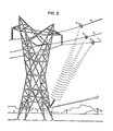
- the voltage measuring system shown in Figure 1 has no direct, highly conductive link between the high voltage of the power line 3 and ground through the measuring device.
- the voltage measurement is encoded and transmitted via radio frequency energy from the measuring device, namely a toroidal state estimator module 5, to a ground receiver separated by an air gap sufficiently large to avoid any high voltage stress conditions on the measuring circuits from the large potential difference between the power line and ground.
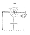
- the power line voltage measurement is obtained from measuring the leakage or charging current created by the interaction of the alternating electric field created by the high voltage in the power line with the essentially toroidal structure of the outer surface of the module 5.
- the fixed spacial relationship of the module with respect to the ground plane determines the value of the leakage or charging current.
- the outer shell 2 of the module is kept at some inter-ratie potential between the power line voltage and ground because of its geometry and spacial relationship to the ground plane.
- the potential of the outer shell 2 is forced to be within a fraction of a volt from the power line voltage by the effect of the electronic circuits within the >module.
- the leakage current following from the outer surface of the toroidal module to ground is essentially proportional to the potential difference between the power line and ground. Since the outer shell of module 5 is nearly at the same voltage as power conductor 3, any change in voltage in conductor 3 will be reflected as a change in charging current flowing from module 5 to ground.
- the apparatus disclosed in this application we have largely overcome these problems by utilizing the entire toroidal case as a charge collecting, capacitor plate. Furthermore, we have DC isolated the toroidal case from the power line conductor by applying a thin hard ceramic coating on the jaws insert. Across this layer of insulation are the inputs to an integrating operational amplifier so configured as to present a very low input impedance across the hard ceramic coating and maintain the voltage difference between the two insulated sides within a fraction of a volt of each other. The current flowing from the power line through to the outer skin of the module is forced to pass through the operational amplifier, digitized, and reported as a voltage measurement.
- Another object of the invention is to provide apparatus of the above character which is hot stick mounted.
- a further object of the invention is to provide apparatus of the above character capable of transmitting measurements to ground.
- Still another object of the invention is to provide apparatus of the above character which may be left on the power conductor for an indefinite time.
- Yet another object of the invention is to provide apparatus of the above character that is not subject to error caused by varying weather conditions.
- a hot stick mounted voltage sensor generally indicated at 5 it shown in Figure 1.
- the module 5 is generally of a toroidal shape. It comprises a housing 2 to which a jaws assembly, generally indicated at 10, is secured via open radial webs 11.
- An R.F. impedance matching network 1 is mounted near the assembly 10, and is connected via associated coaxial cable parts 6, 7, and 8 to a shielded transmitter and to electronics 4 inside the module 5.
- Conductor 32 is connected as described below to the power conductor 3 and to the electronics module 4.
- Module 4 is connected to the outer conducting skin 2 of the module 5.
- the power cable clamping jaws assembly 10 Mounted in the webs 11 of housing 2 is the power cable clamping jaws assembly 10.
- the diameter of the internal opening of this assembly is typically chosen for each specific application so as to accommodate different power cables from 0.5 to 2" in diameter.
- the two metal parts and one conductive resilient part of the cable clamping inserts 10 are shown in detail in Figures 4, 5 and 6.
- the three parts are:
- inner half rings 14 within outer half rings 13 fit inner half rings 14 as shown in Figure 6.
- the inner half rings 14 (to which conductor 32 is connected as shown in Figure 9) are electrically insulated from the outer half rings 13 by a hard coat insulating ceramic coating 37 on the outer surfaces of the inner rings 14. This may be formed by an electro deposition process such as anodizing. Alternatively, the coating may be a non-hydroscopic polymer such as the fluorocarbon TEFLON.
- bolts 16 connecting outer rings 14 to inner rings 13 are insulated from contact with outer ring by insulating inserts 15, typically made of some solid fluorocarbon such as TEFLON. This insert can tolerate the stress associated with the fastening action of bolts 16 that keep the outer and inner rings in intimate mechanical contact.
- a graphite filled, conducting neoprene half ring 17 shown in Figure 6, is shaped so as to resiliently fit within the machined-uninsulated space 39 of inner half ring 14 and the power conductor itself. Ring 17 provides a dual function: first, that of conducting a small amount of current to the voltage measuring circuits, and second, that of providing the mechanical friction for preventing the entire assembly 5 from sliding along the power cable in the event of a strong wind.
- the electrical lead 32 from voltage sensing circuits is attached to the inner half ring 14 by screw 34 fitted into tapped hole 38 as shown in Figures 6 and 9.
- Half ring 14 is fastened to half ring 13 by bolts 16 as shown in Figure 6.
- Bolts 16 are insulated from the conductive body of 13 by insulators 15 and washers 9. The insulation of bolts 16 insures that the effectiveness of hardcoat insulation 37 is preserved and that no low resistance path exists between half rings 13 and 14.
- Half ring 13 is fastened onto ring 30 web structure 11 by bolts 35.
- Bolts 35 are inserted after half ring 14 is attached to half ring 13 through clearance hole 29.
- Bolts 35 engage threaded hole 28 in ring 30, part of web 11.
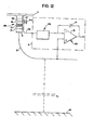
- FIG. 11 it is desired to measure the potential difference V between power conductor 3 and ground 18.
- the outer skin 2 of the module 5 forms a capacitor C . between itself and ground.
- An integrator, generally indicated at 20, consisting of operational amplifier 19 and capacitor 21 is connected between the power conductor 3 and outer skin 2 of module.
- Outer case 2 of the toroidal module 5 is insulated from power line conductor 3 by the interposition of hard coat insulation 37 between rings 13 and 14. This insulation forces any electrical charge flowing from conductor 3 through skin 2 to ground 18 to pass through integrator 20.
- the capacitance 36 formed across insulation 37 by the presence of metal rings 13 and 14 is shunted by the low input impedance of integrator 20. Therefore, at low operating frequencies of a few hundred Hertz, as typically found on power lines, capacitor 36 appears as a virtual open circuit across the very low input impedance of integrator 20.
- the action of the integrator 20 is to force the voltage across insulator 37 and therefore capacitance 36 to a fraction of a volt.
- FIG. 10 gives further detail about the structure of the surge limiting network 22 comprising:
- capacitor 40 The capacitance formed by the insulation 37 between half rings 13 and 14 in Figures 8 and 9 is shown in Figure 10 as equivalent capacitor 40.
- the function of this capacitor is to couple the outer skin 2 of the module 5 and power conductor 3 at high frequencies such as those put out by transmitter 33, through coaxial cable components 6, 7, connector 8, and into space via an impedance matching network 1.
- Capacitance 31 is created by the proximity of the impedance matching network to the outer skin 2 of module 5 and is used to resonate the outer skin 2 at the frequency of interest, typically 950 MHZ. Note that the presence of capacitor 40 does not influence the current to voltage conversion function of operational amplifier 19 or the accuracy of its voltage measuring function.
- capacitor 40 forces all leakage current from the outer skin of the module to ground at the power line operation frequency to flow through operational amplifier 19 so it may be transformed into a voltage to be digitized. Since the integrator 20 forces the low power line frequency voltage across capacitance 36 to be only a fraction of a volt, and capaci - tance 36 is shunted by the low input impedance looking into integrator 20, capacitance 36 has a negligible influence on the voltage measurement function.
Landscapes
- Physics & Mathematics (AREA)
- General Physics & Mathematics (AREA)
- Acoustics & Sound (AREA)
- Measuring Instrument Details And Bridges, And Automatic Balancing Devices (AREA)
- Measurement Of Current Or Voltage (AREA)
- Cable Transmission Systems, Equalization Of Radio And Reduction Of Echo (AREA)
- Emergency Protection Circuit Devices (AREA)
- Tests Of Electronic Circuits (AREA)
- Electrophotography Configuration And Component (AREA)
- Control Or Security For Electrophotography (AREA)
Priority Applications (1)
| Application Number | Priority Date | Filing Date | Title |
|---|---|---|---|
| AT85303896T ATE46577T1 (de) | 1984-11-08 | 1985-06-03 | Auf einer leitung montierte vorrichtung zur messung des leitungspotentials. |
Applications Claiming Priority (2)
| Application Number | Priority Date | Filing Date | Title |
|---|---|---|---|
| US66958984A | 1984-11-08 | 1984-11-08 | |
| US669589 | 1984-11-08 |
Publications (2)
| Publication Number | Publication Date |
|---|---|
| EP0181054A1 true EP0181054A1 (fr) | 1986-05-14 |
| EP0181054B1 EP0181054B1 (fr) | 1989-09-20 |
Family
ID=24686917
Family Applications (1)
| Application Number | Title | Priority Date | Filing Date |
|---|---|---|---|
| EP85303896A Expired EP0181054B1 (fr) | 1984-11-08 | 1985-06-03 | Dispositif monté sur une ligne pour la mesure du potentiel de la ligne |
Country Status (5)
| Country | Link |
|---|---|
| EP (1) | EP0181054B1 (fr) |
| JP (1) | JPH0668520B2 (fr) |
| AT (1) | ATE46577T1 (fr) |
| CA (1) | CA1265844A (fr) |
| DE (1) | DE3573170D1 (fr) |
Cited By (2)
| Publication number | Priority date | Publication date | Assignee | Title |
|---|---|---|---|---|
| EP0267595A1 (fr) * | 1986-11-14 | 1988-05-18 | Niagara Mohawk Power Corporation | Shunt magnétique pour l'alimentation d'un module capteur d'une ligne de transmission |
| CN114594346A (zh) * | 2022-05-09 | 2022-06-07 | 宁波天安智能电网科技股份有限公司 | 一种带电线路的近端测量装置及开关柜 |
Families Citing this family (2)
| Publication number | Priority date | Publication date | Assignee | Title |
|---|---|---|---|---|
| JP6065671B2 (ja) | 2013-03-15 | 2017-01-25 | オムロン株式会社 | 計測装置および取付けユニット |
| US9759798B2 (en) * | 2014-05-13 | 2017-09-12 | General Electric Company | Calibration methods for voltage sensing devices |
Citations (4)
| Publication number | Priority date | Publication date | Assignee | Title |
|---|---|---|---|---|
| US3428896A (en) * | 1963-08-14 | 1969-02-18 | Schweitzer Edmund O Jun | System for transmitting to a remote point a signal that varies as a function of the current flow in a high voltage conductor |
| US4384289A (en) * | 1981-01-23 | 1983-05-17 | General Electric Company | Transponder unit for measuring temperature and current on live transmission lines |
| EP0125050A1 (fr) * | 1983-04-13 | 1984-11-14 | Niagara Mohawk Power Corporation | Dispositif de mesure de température et d'autres paramètres d'une ligne de transport d'énergie électrique |
| EP0125796A1 (fr) * | 1983-04-13 | 1984-11-21 | Niagara Mohawk Power Corporation | Système et appareil pour surveiller et régler un système important de transport d'énergie électrique |
Family Cites Families (1)
| Publication number | Priority date | Publication date | Assignee | Title |
|---|---|---|---|---|
| JPS6450305A (en) * | 1987-08-19 | 1989-02-27 | Shigeo Fujimura | Method for lowering conductor resistance |
-
1985
- 1985-05-16 CA CA000481712A patent/CA1265844A/fr not_active Expired - Fee Related
- 1985-06-03 EP EP85303896A patent/EP0181054B1/fr not_active Expired
- 1985-06-03 AT AT85303896T patent/ATE46577T1/de active
- 1985-06-03 DE DE8585303896T patent/DE3573170D1/de not_active Expired
- 1985-09-03 JP JP60194720A patent/JPH0668520B2/ja not_active Expired - Lifetime
Patent Citations (4)
| Publication number | Priority date | Publication date | Assignee | Title |
|---|---|---|---|---|
| US3428896A (en) * | 1963-08-14 | 1969-02-18 | Schweitzer Edmund O Jun | System for transmitting to a remote point a signal that varies as a function of the current flow in a high voltage conductor |
| US4384289A (en) * | 1981-01-23 | 1983-05-17 | General Electric Company | Transponder unit for measuring temperature and current on live transmission lines |
| EP0125050A1 (fr) * | 1983-04-13 | 1984-11-14 | Niagara Mohawk Power Corporation | Dispositif de mesure de température et d'autres paramètres d'une ligne de transport d'énergie électrique |
| EP0125796A1 (fr) * | 1983-04-13 | 1984-11-21 | Niagara Mohawk Power Corporation | Système et appareil pour surveiller et régler un système important de transport d'énergie électrique |
Cited By (3)
| Publication number | Priority date | Publication date | Assignee | Title |
|---|---|---|---|---|
| EP0267595A1 (fr) * | 1986-11-14 | 1988-05-18 | Niagara Mohawk Power Corporation | Shunt magnétique pour l'alimentation d'un module capteur d'une ligne de transmission |
| US4808916A (en) * | 1986-11-14 | 1989-02-28 | Niagara Mohawk Power Corporation | Power supply magnetic shunt for transmission line sensor module |
| CN114594346A (zh) * | 2022-05-09 | 2022-06-07 | 宁波天安智能电网科技股份有限公司 | 一种带电线路的近端测量装置及开关柜 |
Also Published As
| Publication number | Publication date |
|---|---|
| EP0181054B1 (fr) | 1989-09-20 |
| CA1265844A (fr) | 1990-02-13 |
| ATE46577T1 (de) | 1989-10-15 |
| JPS61129580A (ja) | 1986-06-17 |
| JPH0668520B2 (ja) | 1994-08-31 |
| DE3573170D1 (en) | 1989-10-26 |
Similar Documents
| Publication | Publication Date | Title |
|---|---|---|
| US4795973A (en) | Line mounted apparatus for measuring line potential | |
| US5652521A (en) | Insulation monitoring system for insulated high voltage apparatus | |
| US5574378A (en) | Insulation monitoring system for insulated high voltage apparatus | |
| US10481186B2 (en) | Combined DC current, AC current and voltage sensor for high voltage electric power lines | |
| US4420752A (en) | Real-time parameter sensor-transmitter | |
| US9759755B2 (en) | High voltage measurement systems | |
| US3991367A (en) | Detection of potential on high-voltage transmission lines | |
| US7129693B2 (en) | Modular voltage sensor | |
| WO1996018909A9 (fr) | Systeme de controle pour appareil isole a haute tension | |
| WO1997010515A1 (fr) | Dispositif de detection des decharges electriques dans un objet a tester | |
| WO1994010579A1 (fr) | Procede et appareil de mesure de decharges partielles dans un cable | |
| WO2019194754A1 (fr) | Boîte de connexions comprenant un diviseur de tension de type isolant intégré et un capteur de décharge partielle inductif | |
| WO2020097933A1 (fr) | Capteur de tension et appareil | |
| Mason | Discharge detection and measurements | |
| EP0181054A1 (fr) | Dispositif monté sur une ligne pour la mesure du potentiel de la ligne | |
| EP3929607B1 (fr) | Système de surveillance du courant de fuite d'un appareillage de commutation haute tension ou moyenne tension | |
| KR100305615B1 (ko) | 특고압배전선로의전압검출장치 | |
| JPH08146046A (ja) | 非接触型電圧プローブ装置 | |
| Bendjamin et al. | Remote sensing of ESD through optical and magnetic radiation fields | |
| US20250182926A1 (en) | Connection conductor, arrangement having a connection conductor and use of a connection conductor | |
| JPS592518A (ja) | コロナ放電検出装置および検出方法 | |
| JPH09261813A (ja) | ガス絶縁開閉装置 | |
| JPH0470568A (ja) | サージ電圧センサ | |
| JP2628738B2 (ja) | 電力ケーブル試験装置 | |
| JP2665935B2 (ja) | ケーブルの誘電体損の測定方法 |
Legal Events
| Date | Code | Title | Description |
|---|---|---|---|
| PUAI | Public reference made under article 153(3) epc to a published international application that has entered the european phase |
Free format text: ORIGINAL CODE: 0009012 |
|
| AK | Designated contracting states |
Kind code of ref document: A1 Designated state(s): AT BE CH DE FR GB IT LI LU NL SE |
|
| 17P | Request for examination filed |
Effective date: 19860502 |
|
| 17Q | First examination report despatched |
Effective date: 19880318 |
|
| GRAA | (expected) grant |
Free format text: ORIGINAL CODE: 0009210 |
|
| AK | Designated contracting states |
Kind code of ref document: B1 Designated state(s): AT BE CH DE FR GB IT LI LU NL SE |
|
| REF | Corresponds to: |
Ref document number: 46577 Country of ref document: AT Date of ref document: 19891015 Kind code of ref document: T |
|
| ET | Fr: translation filed | ||
| REF | Corresponds to: |
Ref document number: 3573170 Country of ref document: DE Date of ref document: 19891026 |
|
| ITF | It: translation for a ep patent filed | ||
| PG25 | Lapsed in a contracting state [announced via postgrant information from national office to epo] |
Ref country code: AT Effective date: 19900603 |
|
| PG25 | Lapsed in a contracting state [announced via postgrant information from national office to epo] |
Ref country code: LU Free format text: LAPSE BECAUSE OF NON-PAYMENT OF DUE FEES Effective date: 19900630 |
|
| PLBE | No opposition filed within time limit |
Free format text: ORIGINAL CODE: 0009261 |
|
| STAA | Information on the status of an ep patent application or granted ep patent |
Free format text: STATUS: NO OPPOSITION FILED WITHIN TIME LIMIT |
|
| 26N | No opposition filed | ||
| PG25 | Lapsed in a contracting state [announced via postgrant information from national office to epo] |
Ref country code: NL Effective date: 19910101 |
|
| NLV4 | Nl: lapsed or anulled due to non-payment of the annual fee | ||
| ITTA | It: last paid annual fee | ||
| EAL | Se: european patent in force in sweden |
Ref document number: 85303896.6 |
|
| PGFP | Annual fee paid to national office [announced via postgrant information from national office to epo] |
Ref country code: SE Payment date: 20010612 Year of fee payment: 17 |
|
| PGFP | Annual fee paid to national office [announced via postgrant information from national office to epo] |
Ref country code: CH Payment date: 20010618 Year of fee payment: 17 |
|
| PGFP | Annual fee paid to national office [announced via postgrant information from national office to epo] |
Ref country code: BE Payment date: 20010713 Year of fee payment: 17 |
|
| REG | Reference to a national code |
Ref country code: GB Ref legal event code: IF02 |
|
| PG25 | Lapsed in a contracting state [announced via postgrant information from national office to epo] |
Ref country code: SE Free format text: LAPSE BECAUSE OF NON-PAYMENT OF DUE FEES Effective date: 20020604 |
|
| PG25 | Lapsed in a contracting state [announced via postgrant information from national office to epo] |
Ref country code: LI Free format text: LAPSE BECAUSE OF NON-PAYMENT OF DUE FEES Effective date: 20020630 Ref country code: CH Free format text: LAPSE BECAUSE OF NON-PAYMENT OF DUE FEES Effective date: 20020630 Ref country code: BE Free format text: LAPSE BECAUSE OF NON-PAYMENT OF DUE FEES Effective date: 20020630 |
|
| BERE | Be: lapsed |
Owner name: *NIAGARA MOHAWK POWER CORP. Effective date: 20020630 |
|
| EUG | Se: european patent has lapsed | ||
| REG | Reference to a national code |
Ref country code: CH Ref legal event code: PL |
|
| PGFP | Annual fee paid to national office [announced via postgrant information from national office to epo] |
Ref country code: GB Payment date: 20030528 Year of fee payment: 19 |
|
| PGFP | Annual fee paid to national office [announced via postgrant information from national office to epo] |
Ref country code: FR Payment date: 20030610 Year of fee payment: 19 |
|
| PGFP | Annual fee paid to national office [announced via postgrant information from national office to epo] |
Ref country code: DE Payment date: 20030612 Year of fee payment: 19 |
|
| REG | Reference to a national code |
Ref country code: GB Ref legal event code: 732E |
|
| REG | Reference to a national code |
Ref country code: FR Ref legal event code: TP |
|
| PG25 | Lapsed in a contracting state [announced via postgrant information from national office to epo] |
Ref country code: GB Free format text: LAPSE BECAUSE OF NON-PAYMENT OF DUE FEES Effective date: 20040603 |
|
| PG25 | Lapsed in a contracting state [announced via postgrant information from national office to epo] |
Ref country code: DE Free format text: LAPSE BECAUSE OF NON-PAYMENT OF DUE FEES Effective date: 20050101 |
|
| GBPC | Gb: european patent ceased through non-payment of renewal fee |
Effective date: 20040603 |
|
| PG25 | Lapsed in a contracting state [announced via postgrant information from national office to epo] |
Ref country code: FR Free format text: LAPSE BECAUSE OF NON-PAYMENT OF DUE FEES Effective date: 20050228 |
|
| REG | Reference to a national code |
Ref country code: FR Ref legal event code: ST |