EP0181090A1 - Procédé et dispositif pour la fabrication de rubans microcristallins solidifiés rapidement - Google Patents
Procédé et dispositif pour la fabrication de rubans microcristallins solidifiés rapidement Download PDFInfo
- Publication number
- EP0181090A1 EP0181090A1 EP85307072A EP85307072A EP0181090A1 EP 0181090 A1 EP0181090 A1 EP 0181090A1 EP 85307072 A EP85307072 A EP 85307072A EP 85307072 A EP85307072 A EP 85307072A EP 0181090 A1 EP0181090 A1 EP 0181090A1
- Authority
- EP
- European Patent Office
- Prior art keywords
- tape
- metallic tape
- cooling
- metallic
- coiling
- Prior art date
- Legal status (The legal status is an assumption and is not a legal conclusion. Google has not performed a legal analysis and makes no representation as to the accuracy of the status listed.)
- Granted
Links
- 238000000034 method Methods 0.000 title claims abstract description 16
- 238000001816 cooling Methods 0.000 claims abstract description 68
- 239000002184 metal Substances 0.000 claims abstract description 13
- 238000005520 cutting process Methods 0.000 claims abstract description 12
- 238000004519 manufacturing process Methods 0.000 claims description 18
- 238000005096 rolling process Methods 0.000 claims description 13
- 230000003247 decreasing effect Effects 0.000 claims description 9
- 239000003595 mist Substances 0.000 claims description 8
- 230000002093 peripheral effect Effects 0.000 description 9
- 229910018619 Si-Fe Inorganic materials 0.000 description 6
- 229910008289 Si—Fe Inorganic materials 0.000 description 6
- 229910045601 alloy Inorganic materials 0.000 description 6
- 239000000956 alloy Substances 0.000 description 6
- 230000000694 effects Effects 0.000 description 5
- 238000007711 solidification Methods 0.000 description 5
- 230000008023 solidification Effects 0.000 description 5
- 239000000155 melt Substances 0.000 description 4
- 238000011156 evaluation Methods 0.000 description 2
- XLYOFNOQVPJJNP-UHFFFAOYSA-N water Substances O XLYOFNOQVPJJNP-UHFFFAOYSA-N 0.000 description 2
- 239000002826 coolant Substances 0.000 description 1
- 235000019628 coolness Nutrition 0.000 description 1
- 238000005336 cracking Methods 0.000 description 1
- 230000002950 deficient Effects 0.000 description 1
- 230000000593 degrading effect Effects 0.000 description 1
- 230000006866 deterioration Effects 0.000 description 1
- 238000010586 diagram Methods 0.000 description 1
- 230000003631 expected effect Effects 0.000 description 1
- 238000002474 experimental method Methods 0.000 description 1
- 230000002349 favourable effect Effects 0.000 description 1
- 238000001000 micrograph Methods 0.000 description 1
- 239000000203 mixture Substances 0.000 description 1
- FFNMBRCFFADNAO-UHFFFAOYSA-N pirenzepine hydrochloride Chemical compound [H+].[H+].[Cl-].[Cl-].C1CN(C)CCN1CC(=O)N1C2=NC=CC=C2NC(=O)C2=CC=CC=C21 FFNMBRCFFADNAO-UHFFFAOYSA-N 0.000 description 1
- 238000010583 slow cooling Methods 0.000 description 1
Images


Classifications
-
- B—PERFORMING OPERATIONS; TRANSPORTING
- B22—CASTING; POWDER METALLURGY
- B22D—CASTING OF METALS; CASTING OF OTHER SUBSTANCES BY THE SAME PROCESSES OR DEVICES
- B22D11/00—Continuous casting of metals, i.e. casting in indefinite lengths
- B22D11/06—Continuous casting of metals, i.e. casting in indefinite lengths into moulds with travelling walls, e.g. with rolls, plates, belts, caterpillars
- B22D11/0637—Accessories therefor
- B22D11/0694—Accessories therefor for peeling-off or removing the cast product
-
- Y—GENERAL TAGGING OF NEW TECHNOLOGICAL DEVELOPMENTS; GENERAL TAGGING OF CROSS-SECTIONAL TECHNOLOGIES SPANNING OVER SEVERAL SECTIONS OF THE IPC; TECHNICAL SUBJECTS COVERED BY FORMER USPC CROSS-REFERENCE ART COLLECTIONS [XRACs] AND DIGESTS
- Y10—TECHNICAL SUBJECTS COVERED BY FORMER USPC
- Y10T—TECHNICAL SUBJECTS COVERED BY FORMER US CLASSIFICATION
- Y10T29/00—Metal working
- Y10T29/49—Method of mechanical manufacture
- Y10T29/4998—Combined manufacture including applying or shaping of fluent material
- Y10T29/49988—Metal casting
- Y10T29/49989—Followed by cutting or removing material
-
- Y—GENERAL TAGGING OF NEW TECHNOLOGICAL DEVELOPMENTS; GENERAL TAGGING OF CROSS-SECTIONAL TECHNOLOGIES SPANNING OVER SEVERAL SECTIONS OF THE IPC; TECHNICAL SUBJECTS COVERED BY FORMER USPC CROSS-REFERENCE ART COLLECTIONS [XRACs] AND DIGESTS
- Y10—TECHNICAL SUBJECTS COVERED BY FORMER USPC
- Y10T—TECHNICAL SUBJECTS COVERED BY FORMER US CLASSIFICATION
- Y10T29/00—Metal working
- Y10T29/49—Method of mechanical manufacture
- Y10T29/4998—Combined manufacture including applying or shaping of fluent material
- Y10T29/49988—Metal casting
- Y10T29/49991—Combined with rolling
Definitions
- This invention relates to a method of producing rapidly solidified metallic tapes, particularly rapidly solidified microcrystalline metallic tapes.
- rapidly solidified amorphous metallic tapes are already cooled to about 150-200°C at a position just close to a cooling roll apart thereform. Such a cooled state is also a condition for the production of amorphous metallic tape.
- a method of producing a rapidly solidified microcrystalline metallic tape by continuously pouring molten metal through a nozzle onto surfaces of a pair of cooling members rotating at a high speed to rapidly solidify it and then coiling the resulting rapidly solidified metallic tape, characterized in that said metallic tape transported from the cooling members is cooled and rolled before the coiling after a non-steady portion at at least an initial production stage is cut out from the metallic tape.
- the pouring rate of molten metal is controlled based on an output signal from a meter for measuring tape thickness in a control circuit for the supply of molten metal.
- the rolling before the coiling of the cooled metallic tape is a different speed rolling, and the cooling of the metallic tape is carried out with a gas or a mist (fog).
- the tension of the metallic tape is separately controlled at low tension and high tension.
- an apparatus for producing a rapidly solidified microcrystalline metallic tape by continuously pouring molten metal through a nozzle onto surfaces of a pair of cooling members rotating at a high speed to rapidly solidify it and then coiling the resulting rapidly solidified metallic tabe, comprising a means for cutting out a non-steady port on of the metallic tape travelled from the cooling lembers, a means for measuring a thickness of the metallic tape, a cooling means for the metallic tape, and a means for controlling a tension of the metallic tape.
- numeral 1 is a pouring nozzle
- numeral 2 a flow of molten metal (hereinafter referred to as a melt flow)
- numerals 3, 3' twin-type cooling rolls as a cooling member rotating at a high speed numerals 4, 4' a pair of shear members, numeral 5 a metallic tape, numeral 6 a change-over gate, numeral 7 a chute, numeral 8 a bag, numeral 9 a pair of upper travelling members, numeral 10 a pair of lower travelling members, each of numerals 11, 14, 15 and 18 a deflector roll, numerals 12, 12' cooling headers, numeral 13 an air or mist flow, numerals 16, 16 a pair of pinch rolls, numeral 17 a thickness meter, numeral 19 a coil, numeral 20 a reel, numerals 21 and 22 front and rear region tension meters.
- the melt flow 2 tapped from the pouring nozzle 1 is rapidly solidified between the cooling rolls 3 and 3' to form the metallic tape 5.
- a normal metallic tape can not be obtained because the amount of the melt flow 2 and the amount of the melt in the kissing region defined between the cooling rolls 3 and 3' are non-steady.
- the similar result may be caused at the last production stage or last pouring stage. For this reason, it is difficult to coil such a non-steady tape portion itself different from the case of coiling the normal or steady tape portion and also the normal metallic tape is damaged by the coiled non-steady tape portion.
- the non-steady tape portion is cut as a crop by using the shear members 4, 4' and the change-over gate 6, which is dropped into the bag 8 through the chute 7.
- a tip of the normal or steady tape portion descending downward from the cooling rolls 3, 3' is first caught between a pair of clampers (not shown) each extending between the upper or lower travelling members 9 or 10 near the deflector roll 11 by the driving of the travelling members 9 and 10 and then travelled with the movement of the travelling members 9 and 10 toward the reel 20 and finally coiled therearound to form the coil 19.
- the deflector roll 14 and the pinch roll 16 rise and the deflector roll 15 and the pinch roll 16' descend only in the passing of the clampers so as not to obstruct the passing of the clampers, while these rolls turn back to original positions immediately after the passing of the clampers.
- the clampers are moved up to the predetermined position, respectively, to stop the movement of the travelling members.
- the reel 20 use may preferably be made of a carrousel reel.
- the poor coiling form such as telescope or the like is judged by an operator, which is quantitatively represented by the following equation:
- the best operation is a speed- increasing and decreasing operation wherein only the initial and last travelling stages are performed at a low speed and the other remaining stage is performed at a steady pouring speed or a high speed.
- the good or bad form of the tape tip after the cutting largely exerts on the result of the subsequent operation. Therefore, the good or bad form based on the operator's judgement is quantitatively defined by the following equation:
- the ratio of entwining occurrence is quantitatively calculated by the following equation, provided that the sledding length is 20 m:
- Fig. 3 The relation between the tape thickness and the pouring rate is shown in Fig. 3.
- Fig. 3 there is a substantially linear relation between the tape thickness and the pouring rate when the tape thickness is within a range of 0.15-0.5 mm, but when the tape thickness is outside the above range, it is difficult to make the tape thick or thin.
- the change of the pouring rate at a given peripheral speed of the cooling roll is carried out by means of a control circuit as mentioned later in accordance with a deviation between the set value of tape thickness and the measured value from the tape thickness meter.
- a cooler of air or mist is arranged between the cooling roll and the pinch roll so as to provide a proper cooling rate and an adequate entrance side temperature for the pinch rolls 16, 16'.
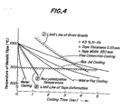
- Such a secondary cooling aims at the insurance of (I) a secondary cooling rate not breaking the rapidly solidified texture, (II) a coiling temperature not breaking the rapidly solidified texture and (LII) a cooling rate not breaking the form of high temperature metallic tape.
- the limit lines of such purposes I, II and III are represented by shadowed lines in Fig. 4 when they are plotted on a curve of tape temperature- cooling time in the metallic tape of 4.5% Si-Fe alloy having a width of 350 mm and a thickness of 0.35 mm. Therefore, in order to achieve the above purposes, it is necessary to locate the secondary cooling rate inside a region defined by these shadowed lines.
- the secondary cooling rate is 1500°C/sec in the water cooling, 200°C/sec in the mist or fog cooling, 100°C/sec in the gas jet cooling, and 60°C/sec in the free convection cooling.
- the cooling rate capable of enough entering into the adequate cooling zone of Fig. 4 is attained by anyone of the mist, fog and gas jet coolings.
- the metallic tape is rolled through pinch rolls 16, 16' to correct the texture (microcrystalline texture) and form of the tape. In this case, a better result is obtained by the different speed operation of the pinch rolls 16, 16'.
- the different speed rolling aims at (a) reduction of tape form (crown), (b) reduction of sharpness, (c) descaling and (d) improvement of texture. If it is intended to achieve these purposes (a)-(d) by the usual rolling (at equal speed), high rolling force is required, resulting in the occurrence of problems such as edge cracking and the like. On the other hand, the expected effects are achieved by the different speed rolling at a low rolling force.
- the tension of the metallic tape it is necessary to make the tension for the metallic tape as low as possible in order to prevent the breakage of the tape, while it is necessary in the coiling machine to make the tension high in order to obtain sufficiently good tape form and coiling form.
- the metallic tape has such a fairly rapid temperature gradient in the direction of production line that the temperature just beneath the cooling roll is 1200°C at maximum and the coiling temperature is about 500°C, the tensile strength of the metallic tap ⁇ changes from 0.1 kg/mm 2 to 8 kg/mm 2 in case of 4.5% Si _'e alloy.
- the tension control is separately carried out at a region between the cooling roll 3, 3' and the pinch roll 16, 16' and a region between the pinch roll 16, 16' and the take-up reel 20.
- the caternary control is performed at a low tension of about 0.1 kg/mm 2 in the front region, while the coiling is performed at a high tension of about 1 kg/mm 2 in the rear region.
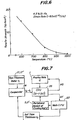
- Fig. 6 is a graph showing the temperature dependency of tensile strength in the metallic tape of 4.5% Si-Fe alloy. Viewing from the coiling conditions, the coiled form is good in the coiling under a high tension. However, since the temperature of the metallic tape just beneath the coiling roll is above 1000°C, the tensile strength at a temperature above 1000°C is not more than 0.5 kg/mm 2 as apparent from Fig. 6, so that such a metallic tape is broken when coiling at a unit tension of not less than 1 kg/mm 2 usually used in the coiling machine.
- the separate tension control as mentioned above is performed in such a manner that the front region (from the cooling rolls 3, 3' to the pinch rolls 16, 16') is substantially the catenary control at low tension and the rear region (from the pinch rolls 16, 16' to the take-up reel 20) is the coiling at high tension.
- Fig. 7 is shown an embodiment of the pouring rate control circuit in the apparatus for producing the rapidly solidified microcrystalline metallic tape described on Fig. 1.
- the above apparatus is operated under the peripheral speed V of the cooling roll 3, 3' and the set tape thickness to established in a main CPU 23, during which an output signal t 1 detected by the tape thickness meter 17, 17' is compared with the set tape thickness to in a comparator 24.
- the coiling can be performed without degrading the form of the rapidly solidified microcrystalline metallic tape, and the handling of the tape can considerably be simplified. Further, the apparatus according to the invention is suitable for practicing the above method.
Landscapes
- Engineering & Computer Science (AREA)
- Mechanical Engineering (AREA)
- Continuous Casting (AREA)
- Metal Rolling (AREA)
Applications Claiming Priority (2)
| Application Number | Priority Date | Filing Date | Title |
|---|---|---|---|
| JP210340/84 | 1984-10-09 | ||
| JP59210340A JPS6188904A (ja) | 1984-10-09 | 1984-10-09 | 微細結晶質急冷薄帯の製造方法および装置 |
Publications (2)
| Publication Number | Publication Date |
|---|---|
| EP0181090A1 true EP0181090A1 (fr) | 1986-05-14 |
| EP0181090B1 EP0181090B1 (fr) | 1988-05-11 |
Family
ID=16587786
Family Applications (1)
| Application Number | Title | Priority Date | Filing Date |
|---|---|---|---|
| EP85307072A Expired EP0181090B1 (fr) | 1984-10-09 | 1985-10-03 | Procédé et dispositif pour la fabrication de rubans microcristallins solidifiés rapidement |
Country Status (5)
| Country | Link |
|---|---|
| US (1) | US4766947A (fr) |
| EP (1) | EP0181090B1 (fr) |
| JP (1) | JPS6188904A (fr) |
| CA (1) | CA1259468A (fr) |
| DE (1) | DE3562569D1 (fr) |
Cited By (4)
| Publication number | Priority date | Publication date | Assignee | Title |
|---|---|---|---|---|
| EP0373535A1 (fr) * | 1988-12-10 | 1990-06-20 | Kawasaki Steel Corporation | Dispositif pour le transfert d'un ruban métallique produit par refroidissement rapide |
| WO2000061320A1 (fr) * | 1999-04-08 | 2000-10-19 | Ishikawajima-Harima Heavy Industries Company Limited | Coulage de bande |
| AU762787B2 (en) * | 1999-04-08 | 2003-07-03 | Bluescope Steel Limited | Casting strip |
| CN103008448A (zh) * | 2012-12-03 | 2013-04-03 | 河南亚东量具有限公司 | 一种卷尺自动卷簧设备 |
Families Citing this family (8)
| Publication number | Priority date | Publication date | Assignee | Title |
|---|---|---|---|---|
| JPH07115041B2 (ja) * | 1987-03-11 | 1995-12-13 | 日本鋼管株式会社 | 無方向性高Si鋼板の製造方法 |
| US4964583A (en) * | 1987-11-19 | 1990-10-23 | Kawasaki Steel Corporation | Method of transporting rapidly quenched ribbon and apparatus therefor |
| JPH0741281B2 (ja) * | 1988-04-26 | 1995-05-10 | 川崎製鉄株式会社 | 長手方向に溶断した鋼スラブの冷延コイル端部の表面性状異常防止方法 |
| JP2911733B2 (ja) | 1993-10-04 | 1999-06-23 | 新日本製鐵株式会社 | 高靭性非晶質合金薄帯およびその製造方法 |
| AU5994301A (en) * | 2000-05-26 | 2001-12-11 | Ishikawajima Harima Heavy Ind | Hot rolling thin strip |
| AUPQ779900A0 (en) * | 2000-05-26 | 2000-06-22 | Bhp Steel (Jla) Pty Limited | Hot rolling thin strip |
| JP4918155B2 (ja) | 2010-09-28 | 2012-04-18 | 三菱日立製鉄機械株式会社 | 熱延鋼帯の製造装置及び製造方法 |
| GB2539010B (en) * | 2015-06-03 | 2019-12-18 | Vacuumschmelze Gmbh & Co Kg | Method of fabricating an article for magnetic heat exchange |
Citations (2)
| Publication number | Priority date | Publication date | Assignee | Title |
|---|---|---|---|---|
| FR1198006A (fr) * | 1958-01-31 | 1959-12-04 | Pechiney Prod Chimiques Sa | Coulée continue des métaux |
| WO1985001901A1 (fr) * | 1983-11-01 | 1985-05-09 | Sheneman Ralph L | Bande metallique coulee revetue |
Family Cites Families (17)
| Publication number | Priority date | Publication date | Assignee | Title |
|---|---|---|---|---|
| US2233578A (en) * | 1937-11-04 | 1941-03-04 | Western Cartridge Co | Method of making battery cans |
| FR1043564A (fr) * | 1951-04-05 | 1953-11-10 | Ile D Etudes De Centrifugation | Procédé et dispositifs pour la fabrication de corps creux métalliques |
| US3147521A (en) * | 1961-08-10 | 1964-09-08 | Boehm Arnold Henry | Continuous casting and forming process |
| US3293692A (en) * | 1964-02-26 | 1966-12-27 | Olin Mathieson | Apparatus for forming rigid porous metal body |
| GB1595628A (en) * | 1977-03-07 | 1981-08-12 | Furukawa Electric Co Ltd | Method of producing amorphous metal tapes |
| JPS5575861A (en) * | 1978-12-04 | 1980-06-07 | Furukawa Electric Co Ltd:The | Continuous producing equipment of metal bar or plate |
| JPS603899B2 (ja) * | 1979-05-25 | 1985-01-31 | 株式会社日立製作所 | 薄板製造装置 |
| JPS561206A (en) * | 1979-06-15 | 1981-01-08 | Matsushita Electric Ind Co Ltd | Manufacture of metallic thin sheet |
| JPS564348A (en) * | 1979-06-20 | 1981-01-17 | Hitachi Ltd | Method and device for production of sheet |
| US4323419A (en) * | 1980-05-08 | 1982-04-06 | Atlantic Richfield Company | Method for ribbon solar cell fabrication |
| US4316497A (en) * | 1980-05-09 | 1982-02-23 | Atlantic Richfield Company | Method an apparatus for feed on to a take-up reel in high speed silico |
| JPS56165543A (en) * | 1980-05-23 | 1981-12-19 | Nippon Steel Corp | Method for continuous casting of metal |
| US4439813A (en) * | 1981-07-21 | 1984-03-27 | Ibm Corporation | Thin film discrete decoupling capacitor |
| JPS5897468A (ja) * | 1981-12-04 | 1983-06-09 | Kawasaki Steel Corp | 金属薄帯製造方法およびその装置 |
| JPS58167060A (ja) * | 1982-02-26 | 1983-10-03 | Sumitomo Metal Ind Ltd | 薄鋼板の製造方法及びその装置 |
| JPS60118360A (ja) * | 1983-11-30 | 1985-06-25 | Hitachi Ltd | 高速薄板製造設備 |
| JPS61235043A (ja) * | 1985-04-10 | 1986-10-20 | Hitachi Zosen Corp | 薄板連続鋳造装置 |
-
1984
- 1984-10-09 JP JP59210340A patent/JPS6188904A/ja active Granted
-
1985
- 1985-10-03 EP EP85307072A patent/EP0181090B1/fr not_active Expired
- 1985-10-03 DE DE8585307072T patent/DE3562569D1/de not_active Expired
- 1985-10-08 CA CA000492434A patent/CA1259468A/fr not_active Expired
-
1987
- 1987-01-30 US US07/009,564 patent/US4766947A/en not_active Expired - Fee Related
Patent Citations (2)
| Publication number | Priority date | Publication date | Assignee | Title |
|---|---|---|---|---|
| FR1198006A (fr) * | 1958-01-31 | 1959-12-04 | Pechiney Prod Chimiques Sa | Coulée continue des métaux |
| WO1985001901A1 (fr) * | 1983-11-01 | 1985-05-09 | Sheneman Ralph L | Bande metallique coulee revetue |
Cited By (5)
| Publication number | Priority date | Publication date | Assignee | Title |
|---|---|---|---|---|
| EP0373535A1 (fr) * | 1988-12-10 | 1990-06-20 | Kawasaki Steel Corporation | Dispositif pour le transfert d'un ruban métallique produit par refroidissement rapide |
| WO2000061320A1 (fr) * | 1999-04-08 | 2000-10-19 | Ishikawajima-Harima Heavy Industries Company Limited | Coulage de bande |
| AU762787B2 (en) * | 1999-04-08 | 2003-07-03 | Bluescope Steel Limited | Casting strip |
| US6698498B1 (en) | 1999-04-08 | 2004-03-02 | Castrip, Llc | Casting strip |
| CN103008448A (zh) * | 2012-12-03 | 2013-04-03 | 河南亚东量具有限公司 | 一种卷尺自动卷簧设备 |
Also Published As
| Publication number | Publication date |
|---|---|
| JPS6188904A (ja) | 1986-05-07 |
| EP0181090B1 (fr) | 1988-05-11 |
| CA1259468A (fr) | 1989-09-19 |
| JPH0471602B2 (fr) | 1992-11-16 |
| US4766947A (en) | 1988-08-30 |
| DE3562569D1 (en) | 1988-06-16 |
Similar Documents
| Publication | Publication Date | Title |
|---|---|---|
| EP0181090A1 (fr) | Procédé et dispositif pour la fabrication de rubans microcristallins solidifiés rapidement | |
| CA1213814A (fr) | Methode et dispositif de fabrication continue de bandes de plomb ou de ses alliages | |
| US5528816A (en) | Method and plant to produce strip, starting from thin slabs | |
| Zapuskalov | Effect of coiling operation on strip quality of 4.5% Si steel in twin-roll casting process | |
| EP0568211B1 (fr) | Procédé et dispositif de coulée continue de produits métalliques minces sur un cylindre en rotation | |
| JPH08510962A (ja) | 半製品の製造方法及び装置 | |
| JPS61108452A (ja) | 急冷薄帯の巻取り方法 | |
| JPH0890036A (ja) | 熱間圧延巻取温度制御方法 | |
| JPH0810919A (ja) | 含ニッケル鋼の連続鋳造方法 | |
| JPH04305338A (ja) | 薄鋼板用鋼片の連続鋳造方法 | |
| JP2532306B2 (ja) | 連続鋳造法 | |
| JP3633573B2 (ja) | 連続鋳造方法 | |
| JP2863013B2 (ja) | 薄スラブの鋳造・圧延方法 | |
| JP2894131B2 (ja) | 大型鋳片の製造方法 | |
| JP2981139B2 (ja) | 鋼帯の冷間圧延方法 | |
| JPH04313453A (ja) | 連続鋳造法 | |
| KR100423519B1 (ko) | 연속주조시 전단 제어방법 | |
| JP2000000638A (ja) | ビレットの連続鋳造方法 | |
| JP3298784B2 (ja) | 連続熱間圧延方法 | |
| JPH08215748A (ja) | 熱間圧延におけるネッキング防止方法 | |
| JP2903844B2 (ja) | 連続鋳造における鋳込み終了方法 | |
| CN1600474A (zh) | 一种薄带连铸的开浇方法 | |
| JPH06285520A (ja) | 冷間タンデム圧延機における走間板厚変更時の張力制御方法 | |
| JPS6117561B2 (fr) | ||
| JPH08197202A (ja) | 急冷凝固薄帯の巻取り方法 |
Legal Events
| Date | Code | Title | Description |
|---|---|---|---|
| PUAI | Public reference made under article 153(3) epc to a published international application that has entered the european phase |
Free format text: ORIGINAL CODE: 0009012 |
|
| AK | Designated contracting states |
Kind code of ref document: A1 Designated state(s): DE FR GB SE |
|
| 17P | Request for examination filed |
Effective date: 19860728 |
|
| 17Q | First examination report despatched |
Effective date: 19861211 |
|
| GRAA | (expected) grant |
Free format text: ORIGINAL CODE: 0009210 |
|
| AK | Designated contracting states |
Kind code of ref document: B1 Designated state(s): DE FR GB SE |
|
| REF | Corresponds to: |
Ref document number: 3562569 Country of ref document: DE Date of ref document: 19880616 |
|
| ET | Fr: translation filed | ||
| PLBE | No opposition filed within time limit |
Free format text: ORIGINAL CODE: 0009261 |
|
| PLBI | Opposition filed |
Free format text: ORIGINAL CODE: 0009260 |
|
| 26 | Opposition filed |
Opponent name: SUNDWIGER EISENHUETTE MASCHINENFABRIK GRAH & CO. Effective date: 19890209 |
|
| 26N | No opposition filed | ||
| PLBN | Opposition rejected |
Free format text: ORIGINAL CODE: 0009273 |
|
| STAA | Information on the status of an ep patent application or granted ep patent |
Free format text: STATUS: OPPOSITION REJECTED |
|
| 27O | Opposition rejected |
Effective date: 19901113 |
|
| EAL | Se: european patent in force in sweden |
Ref document number: 85307072.0 |
|
| PGFP | Annual fee paid to national office [announced via postgrant information from national office to epo] |
Ref country code: GB Payment date: 19960924 Year of fee payment: 12 |
|
| PGFP | Annual fee paid to national office [announced via postgrant information from national office to epo] |
Ref country code: FR Payment date: 19961009 Year of fee payment: 12 |
|
| PGFP | Annual fee paid to national office [announced via postgrant information from national office to epo] |
Ref country code: SE Payment date: 19961016 Year of fee payment: 12 |
|
| PG25 | Lapsed in a contracting state [announced via postgrant information from national office to epo] |
Ref country code: GB Free format text: LAPSE BECAUSE OF NON-PAYMENT OF DUE FEES Effective date: 19971003 |
|
| PG25 | Lapsed in a contracting state [announced via postgrant information from national office to epo] |
Ref country code: SE Free format text: LAPSE BECAUSE OF NON-PAYMENT OF DUE FEES Effective date: 19971004 |
|
| PGFP | Annual fee paid to national office [announced via postgrant information from national office to epo] |
Ref country code: DE Payment date: 19971010 Year of fee payment: 13 |
|
| PG25 | Lapsed in a contracting state [announced via postgrant information from national office to epo] |
Ref country code: FR Free format text: THE PATENT HAS BEEN ANNULLED BY A DECISION OF A NATIONAL AUTHORITY Effective date: 19971031 |
|
| GBPC | Gb: european patent ceased through non-payment of renewal fee |
Effective date: 19971003 |
|
| EUG | Se: european patent has lapsed |
Ref document number: 85307072.0 |
|
| REG | Reference to a national code |
Ref country code: FR Ref legal event code: ST |
|
| PG25 | Lapsed in a contracting state [announced via postgrant information from national office to epo] |
Ref country code: DE Free format text: LAPSE BECAUSE OF NON-PAYMENT OF DUE FEES Effective date: 19990803 |