EP0181224A2 - Differenzdruckkapillarviskosimeter für die von Strömungsgeschwindigkeit und Temperaturschwankungen unabhängige Messung der Viskosität - Google Patents
Differenzdruckkapillarviskosimeter für die von Strömungsgeschwindigkeit und Temperaturschwankungen unabhängige Messung der Viskosität Download PDFInfo
- Publication number
- EP0181224A2 EP0181224A2 EP85308117A EP85308117A EP0181224A2 EP 0181224 A2 EP0181224 A2 EP 0181224A2 EP 85308117 A EP85308117 A EP 85308117A EP 85308117 A EP85308117 A EP 85308117A EP 0181224 A2 EP0181224 A2 EP 0181224A2
- Authority
- EP
- European Patent Office
- Prior art keywords
- capillary tube
- solvent
- pressure drop
- measuring
- viscosity
- Prior art date
- Legal status (The legal status is an assumption and is not a legal conclusion. Google has not performed a legal analysis and makes no representation as to the accuracy of the status listed.)
- Granted
Links
Images


Classifications
-
- G—PHYSICS
- G01—MEASURING; TESTING
- G01N—INVESTIGATING OR ANALYSING MATERIALS BY DETERMINING THEIR CHEMICAL OR PHYSICAL PROPERTIES
- G01N11/00—Investigating flow properties of materials, e.g. viscosity, plasticity; Analysing materials by determining flow properties
- G01N11/02—Investigating flow properties of materials, e.g. viscosity, plasticity; Analysing materials by determining flow properties by measuring flow of the material
- G01N11/04—Investigating flow properties of materials, e.g. viscosity, plasticity; Analysing materials by determining flow properties by measuring flow of the material through a restricted passage, e.g. tube, aperture
- G01N11/08—Investigating flow properties of materials, e.g. viscosity, plasticity; Analysing materials by determining flow properties by measuring flow of the material through a restricted passage, e.g. tube, aperture by measuring pressure required to produce a known flow
-
- G—PHYSICS
- G01—MEASURING; TESTING
- G01N—INVESTIGATING OR ANALYSING MATERIALS BY DETERMINING THEIR CHEMICAL OR PHYSICAL PROPERTIES
- G01N11/00—Investigating flow properties of materials, e.g. viscosity, plasticity; Analysing materials by determining flow properties
- G01N2011/0006—Calibrating, controlling or cleaning viscometers
-
- G—PHYSICS
- G01—MEASURING; TESTING
- G01N—INVESTIGATING OR ANALYSING MATERIALS BY DETERMINING THEIR CHEMICAL OR PHYSICAL PROPERTIES
- G01N30/00—Investigating or analysing materials by separation into components using adsorption, absorption or similar phenomena or using ion-exchange, e.g. chromatography or field flow fractionation
- G01N30/02—Column chromatography
- G01N30/62—Detectors specially adapted therefor
- G01N2030/621—Detectors specially adapted therefor signal-to-noise ratio
- G01N2030/625—Detectors specially adapted therefor signal-to-noise ratio by measuring reference material, e.g. carrier without sample
-
- G—PHYSICS
- G01—MEASURING; TESTING
- G01N—INVESTIGATING OR ANALYSING MATERIALS BY DETERMINING THEIR CHEMICAL OR PHYSICAL PROPERTIES
- G01N30/00—Investigating or analysing materials by separation into components using adsorption, absorption or similar phenomena or using ion-exchange, e.g. chromatography or field flow fractionation
- G01N30/02—Column chromatography
- G01N30/26—Conditioning of the fluid carrier; Flow patterns
- G01N30/28—Control of physical parameters of the fluid carrier
- G01N30/32—Control of physical parameters of the fluid carrier of pressure or speed
-
- G—PHYSICS
- G01—MEASURING; TESTING
- G01N—INVESTIGATING OR ANALYSING MATERIALS BY DETERMINING THEIR CHEMICAL OR PHYSICAL PROPERTIES
- G01N33/00—Investigating or analysing materials by specific methods not covered by groups G01N1/00 - G01N31/00
- G01N33/44—Resins; Plastics; Rubber; Leather
- G01N33/442—Resins; Plastics
Definitions
- This invention relates to capillary viscometers. More specifically, it relates to differential pressure capillary viscometers which may be used alone to measure the viscosity of fluids or together with a chromatograph to obtain accurate viscosity information for determining molecular weight distributions.
- a capillary viscometer is often used to measure the absolute viscosity of a given fluid. For many purposes, however, it is necessary to know the relative viscosity of two fluids. Relative viscosity is often determined experimentally by measuring the absolute viscosity of each fluid separately with a capillary viscometer and then calculating the ratio.
- Relative viscosity is of particular importance in polymer research and manufacturing since it can be used to measure molecular weights and to determine molecular weight distributions, which provide important information relating to the physical properties of polymers.
- a comparison of the viscosity behavior of two polymers of the same molecular weight, for example, is used as a measure of the degree of branching.
- One of the oldest means used to obtain such information is to measure the viscosity ofknown concentration of a polymer in a solvent.
- Inherent and intrinsic viscosities are important polymer characterization parameters.
- the intrinsic viscosity provides an indication of the size of the polymer molecules.
- the value of [ ⁇ ] is not a function of polymer concentration or the viscosity of the solvent medium.
- the value of [ ⁇ ] for a linear polymer in a specific solvent is related to the polymer molecular weight M through the Mark-Houwink Equation: where K and a are Mark-Houwink viscosity constants. some of which are available in polymer handbooks.
- Prior art viscometers have been designed to measure viscosities in a number of ways.
- An early device used a single capillary of known diameter and length. Both the volume rate of flow of the solution and the pressure drop for flow through the capillary are measured. The pressure drop is usually measured by an electrical signal generated by a pressure transducer. The various viscosities are then calculated from the known geometrical parameters of the capillary.
- Viscosity measurements are also very sensitive to temperature fluctuations. These can occur when the temperature of the solvent supply is not controlled carefully and is affected by environmental temperature changes. Sample injection can also cause temperature upsets. Measuring viscosity independent of temperature fluctuations is therefore important in obtaining accurate viscosity measurements.
- the Blair viscometer used a flow restrictor between the solvent supply and capillary to try to maintain the flow rates constant. Also, it measured relative viscosity by taking separate pressure drop measurements, first when polymer solution and then when pure solvent flowed through the capillary.
- two capillary tubes were arranged in parallel, one filled with polymer solution and the other only with solvent. In another version, the two tubes were connected in series, with pure solvent flowing through one and polymer solution through the other, and the pressure drop across each was measured.
- the capillary tubes had to be exactly matched so as to be identical in diameter and length. Otherwise, the pressure drops across both would not be equal for a given flow rate. If, however, the capillaries were not maintained at the identical temperature, they became "unmatched" in pressure drop, which resulted in lower sensitivity. Fluctuations in flow rate as well as temperature also adversely affected the accuracy of Blair's relative viscosity measurements.
- a capillary viscometer which is similar to Blair's preferred parallel arrangement for measuring the differential pressure across a capillary bridge is described in U.S. Patent 4,463,598 granted August 7, 1984, to Max A. Haney.
- This device as in the case of Blair's, requires the capillaries to be matched.
- Haney like Blair, does not compensate for flow rate and temperature fluctuations in real time when it measures the differential pressure drops. Consequently, neither Blair nor Haney provides viscosity measurements independent of flow rate and temperature fluctuations.
- a more accurate viscometer is also needed in size exclusion chromatography (SEC) such as gel permeation chromatography (GPC) analysis.
- SEC size exclusion chromatography
- GPC gel permeation chromatography
- This technique has become widely used because of its ability to separate polymeric materials in a dilute solution according to molecular size. It utilizes columns containing porous packings which are capable of separating the molecules in a multicomponent polymer sample according to their size. The polymer components migrate through the column at different velocities and elute separately from the column at different times. The largest polymer molecules elute first and the smallest molecules last. By detecting the amount of polymer fractions in the eluant, a GPC elution curve is generated which reflects the molecular weight distribution of the multicomponent polymer sample.
- a detector is commonly used for providing the weight concentration profile of the elution curve.
- the polymer sample concentration profile is commonly obtained by using a differential refractometer.
- Molecular weight information is provided indirectly by the time of elution (also referred to as retention time) of the different polymer components in the sample. By using standardized correlations, which are often not available, the molecular weight distribution of the polymer sample could be calculated.
- a continuous capillary type viscometer was proposed for GPC analysis by A. C. Ouano in J. Polym. Sci. Part A-1, 10, 2169 (1972).
- a single capillary tube was placed in series with a concentration detector such as a differential refractometer at the exit end of the GPC column.
- concentration detector such as a differential refractometer
- the pressure drop across the capillary was measured and recorded.
- a peak in the AP recording trace was detected.
- the present invention provides a means for measuring either the intrinsic or inherent viscosity of a solute in solution with a solvent by a process which is independent of flow rate and temperature fluctuations comprising the steps of:
- An apparatus for accomplishing this process comprises in combination:
- solvent supply means for supplying solvent to flow through both capillary tubes
- solution supply means for supplying a sample of the solute to the solvent stream so that solution flows through the second capillary tube
- amplification means preferably logarithmic amplification means for receiving and processing the pressure drop signals for use in measuring either the intrinsic or inherent viscosity of the solute independent of the flow rate and temperature fluctuations of the solution and the solvent.
- the invention may also be employed with GPC or other SEC analysis means to obtain information on the molecular weight distribution of polymer material.
- the invention may also be used as an in-line process monitor or as a stand-alone viscometer.
- the present invention utilizes two capillaries arranged in series.
- a pressure transducer is connected across each capillary to monitor simultaneously the pressure drop of fluid flowing through each tube.
- the pressure drop measured across the first, or analytical capillary will correspond to the sample liquid, in this case, the polymer solvent solution, ⁇ P p
- the pressure drop across the second, or reference capillary will correspond to the reference liquid, in this case pure solvent, ⁇ P s .
- the signals generated by the pressure transducers are fed to an amplification means rather than being linearly subtracted as has been done in the prior art.
- the signals of the pressure drop across the analytical capillary, ⁇ P p , and the pressure drop across the reference capillary. ⁇ P s are processed as a ratio of ⁇ P p / ⁇ P s in real time by the amplification means.
- the real time signal processing means can be accomplished using an analog divider as described in "Burr Brown Operation Amplifier Design and Applications” (1971) McGraw Hill p. 279 or by a high speed computer which reads the signals APp/AP s in real time.
- a differential logarithmic amplifier is used to process the pressure drop differential of the ratio APp/APs in real time. It also eliminates the need to match the dimensions of the capillaries.
- the output of the differential logarithmic amplifier is a real time measure of the natural logarithmic of the relative viscosity. ln ⁇ r .
- the pressure drop ⁇ P signal generated by the pressure transducer is related to the viscosity of fluid flowing through the capillary in accordance with the following relationship:
- (S) will be determined as follows: G1 or G2 is initially adjusted while pumping one fluid through the system so that: After this adjustment, (S) is now a direct measure of the relative viscosity of the fluids flowing throught the capillaries and is independent of flow rate.
- ⁇ r is the relative viscosity ⁇ p / ⁇ s and Gland G 2 are the electronic gains in the ⁇ P signal measured across the analytical and reference capillary, respectively.
- the first term is a flow rate and temperature independent instrument constant of the capillary mismatch that can easily be eliminated by suitable zero offset calibration in the instrument electronics. Alternatively, it may be eliminated by matching G 1 K 1 to G 2 K 2 electronically.
- the second term is the natural logarithm of the relative viscosity.
- This output signal (S) thus will give a direct read out of the inherent and intrinsic viscosities as noted earlier according to the following relationship: where polymer weight concentration C can be determined by a detector such as the differential refractometer located in the fluid flow path.
- the signal output is independent of flow rate and temperature fluctuations and responds only to the polymer viscosity. Moreover, there is no need to match the capillaries.
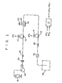
- FIG 1 illustrates one embodiment of the viscometer of the present invention which can be used in batch sample viscosity determinations.
- Two capillaries are arranged in series. The first is the reference capillary 10 through which only solvent flows. The second is the analytical capillary 12 through which the polymer-solvent solution will flow.
- the capillaries are long tubes of small internal diameter formed of glass, metal or any other suitable material.
- each transducer 14 and 16 Connected across each respective capillary are pressure transducers 14 and 16 which monitor the pressure drops of fluid flowing through the capillaries. Each transducer will generate an electrical signal corresponding to the pressure drop across its capillary. These signals are fed to a differential logarithmic amplifier 17, such as a Burr Brown Log 100 JP.
- Solvent is introduced from a reservoir 18 via a pump 20.
- the polymer sample is injected into the solvent stream from a sample loop 22 via a sample injection valve 24, which may be a two-position 6-port valve. This type of valve is sold by Valco Instruments Inc., under the designation Valco CV6UHPA.
- the sample loop is located downstream from the reference capillary 10 but before the analytical capillary 12.
- Solvent is pumped to the reference capillary through a flow resistor 26 which is a long tube of small internal diameter.
- This flow resistor and a second flow resistor 28 located downstream from the analytical capillary 12 provide back pressure which improves the performance of the pump 20 and pressure transducers 14 and 16.
- a third flow resistor 32 provides a solvent flow by-pass around the sample injection valve 24. This ensures continuous flow during sample injection and reduces flow rate upsets caused by the valve switching during sample injection.
- a concentration detector 34 such as a differential refractometer cell is placed at the end of the stream. Other types of concentration detectors such as ultraviolet or infrared devices may be used depending upon the particular type of sample used. After it passes the concentration detector 34, the sample stream empties into a waste receptacle 36. Where the concentration of the sample is known, a concentration detector is not needed in order to calculate either the inherent or intrinsic viscosity of the polymer.
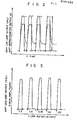
- the viscometer of FIG 1 will generate two separate signal detector traces for recording.
- the signals from pressure transducers 1 4 and 16 will, by employing a differential logarithmic amplifier, be processed to generate a viscosity (in ⁇ r ) trace while the concentration detector 34 will generate a concentration C trace. Both will occur simultaneously and repeatedly from successive sample injections as shown in FIG 2.
- the sample used to obtain the signal traces of FIG 2 was polystyrene having a molecular weight of 17,500 in THF solvent at 1 percent weight concentration. From the ln ⁇ r and C signals, both the inherent and intrinsic viscosity of the polymer sample can be calculated directly and accurately from the ratio of the signal amplitudes shown in FIG 2.
- FIG 4 illustrates a second embodiment of the viscometer of the present invention where like elements are designated by the same reference numerals.
- the viscometer here is used as a GPC- viscosity detector, but it should be understood that other separation devices could also be used.
- a GPC column set 40 is located between the sample loop 22 and injection valve 24 and the analytical capillary 12. It should be noted that the relative positions of the analytical capillary 12 and reference capillary 1 0 have been reversed in this embodiment.
- a large depository column 42 has been added and the concentration detector 34 is located between the analytical and reference capillary. Also the flow resistors 26, 28 and 32 have been omitted as has the pulse damper 30.
- the purpose of column 42 is to dilute the polymer-solvent solution with solvent so that the reference capillary 10 essentially has only solvent passing through it during the detection operation.
- a multicomponent polymer mixture sample is injected through sample loop 22 and valve 24.
- the sample is carried by the solvent and is introduced into the GPC columns 40 where the polymer molecules are separated according to size.
- the larger molecules are eluted first at the other end as described earlier.
- the concentration detector 34 detects each polymer component and provides a concentration C signal at the elution time. corresponding to each successively smaller molecular weight polymer component.
- the AP viscosity detection traces will also occur at the corresponding retention time since each component will generate a pressure drop signal across the analytical capillary 12 as it is eluted from the GPC column set 40.
- the AP signals are fed to a differential logarithmic amplifier which will process them as explained above and generate traces corresponding to the natural logarithm of the relative viscosity in ⁇ r of each respective polymer component. These traces occur simultaneously with the GPC concentration traces.
- FIG 5 graphically illustrates these recorded traces for 3-component polystyrene mixture of 0.25 percent weight concentration in THF solvent flowing at the rate of 2 ml/min.
- the top recording shows the concentration profile of the repeated GPC separation of the 3-component mixture as detected by a differential refractometer.
- the bottom trace records the same GPC separation, but with the viscometer signal of the log-amplifier output.
- the viscometer response is shown, as expected, as being highly biased in favoring the detection of the high molecular weight component.
- the close similarity of the traces for repeat GPC runs demonstrates the good reproducibility of the viscometer for GPC and other SEC applications. This is due to the fine baseline stability as shown in the lower trace which'is due in turn to the removal of the dependence on flow rate and temperature upsets and variations.
- temperature control is important in conventional capillary viscometers since small temperature variations in the liquids can greatly affect the accuracy of the viscosity measurements. No special temperature controls are necessary with the present invention. Due to the real time signal processing and the capillary arrangements, temperature fluctuations do not affect the accuracy of the viscosity measurement. This is because the liquid in the analytical and reference capillaries will essentially be at the same temperature each time the relative viscosity signal is processed in real time from the simultaneous pressure drops across each capillary.
- the solution supply means may comprise a valve for introducing the solute sample, and a restricted flow by-pass around the valve to provide continuous solvent flow during switching of the valve.
- the step of passing the sample through column means further comprises introducing the sample into the solvent through the valve.
- a dilution means may be employed between the capillary tubes to ensure that essentially only solvent flows through the second capillary tube while the pressure drops across both capillary tubes are being measured.
- the apparatus may further comprise a flow resistor before the first capillary tube and a flow resistor after the second capillary tube.
- the reference liquid is preferably a solvent for the sample liquid.
- the viscosity of the reference liquid is preferably a known value.
Landscapes
- Physics & Mathematics (AREA)
- Health & Medical Sciences (AREA)
- Life Sciences & Earth Sciences (AREA)
- Chemical & Material Sciences (AREA)
- Analytical Chemistry (AREA)
- Biochemistry (AREA)
- General Health & Medical Sciences (AREA)
- General Physics & Mathematics (AREA)
- Immunology (AREA)
- Pathology (AREA)
- Investigating Or Analyzing Materials Using Thermal Means (AREA)
- Liquid Carbonaceous Fuels (AREA)
- Agricultural Chemicals And Associated Chemicals (AREA)
Applications Claiming Priority (4)
| Application Number | Priority Date | Filing Date | Title |
|---|---|---|---|
| US669017 | 1984-11-07 | ||
| US06/669,017 US4578990A (en) | 1984-11-07 | 1984-11-07 | Differential pressure capillary viscometer for measuring viscosity independent of flow rate and temperature fluctuations |
| US792041 | 1985-10-31 | ||
| US06/792,041 US4627271A (en) | 1984-11-07 | 1985-10-31 | Differential pressure capillary viscometer for measuring viscosity independent of flow rate and temperature fluctuations |
Publications (3)
| Publication Number | Publication Date |
|---|---|
| EP0181224A2 true EP0181224A2 (de) | 1986-05-14 |
| EP0181224A3 EP0181224A3 (en) | 1987-06-24 |
| EP0181224B1 EP0181224B1 (de) | 1992-07-29 |
Family
ID=27100043
Family Applications (1)
| Application Number | Title | Priority Date | Filing Date |
|---|---|---|---|
| EP85308117A Expired - Lifetime EP0181224B1 (de) | 1984-11-07 | 1985-11-07 | Differenzdruckkapillarviskosimeter für die von Strömungsgeschwindigkeit und Temperaturschwankungen unabhängige Messung der Viskosität |
Country Status (5)
| Country | Link |
|---|---|
| US (1) | US4627271A (de) |
| EP (1) | EP0181224B1 (de) |
| JP (1) | JPS61159131A (de) |
| CA (1) | CA1246893A (de) |
| DE (1) | DE3586416T2 (de) |
Cited By (3)
| Publication number | Priority date | Publication date | Assignee | Title |
|---|---|---|---|---|
| EP1152234A3 (de) * | 2000-05-03 | 2004-01-02 | WGE Dr. Bures GmbH & Co. KG | Viskosimeter |
| US6708553B2 (en) | 2000-05-03 | 2004-03-23 | Wge Dr. Bures Gmbh & Co. Kg | Viscosimeter |
| US6877361B2 (en) * | 2001-04-30 | 2005-04-12 | Wge Dr. Bures Gmbh & Co. Kg | Viscosimeter |
Families Citing this family (28)
| Publication number | Priority date | Publication date | Assignee | Title |
|---|---|---|---|---|
| US4798081A (en) * | 1985-11-27 | 1989-01-17 | The Dow Chemical Company | High temperature continuous viscometry coupled with analytic temperature rising elution fractionation for evaluating crystalline and semi-crystalline polymers |
| US4793174A (en) * | 1987-10-05 | 1988-12-27 | E. I. Du Pont De Nemours And Company | Differential pressure capillary viscometer |
| US4876882A (en) * | 1989-01-30 | 1989-10-31 | E. I. Du Pont De Nemours And Company | Viscosity detection method for liquid chromatography systems with carrier liquids having time-varying viscosity |
| US4972701A (en) * | 1989-08-31 | 1990-11-27 | E. I. Du Pont De Nemours And Company | Osmotic method for determining the molecular weight of solutes in solution with a solvent |
| DE4423988A1 (de) * | 1994-07-07 | 1996-01-11 | Kraft Jacobs Suchard R & D Inc | Verfahren zum kontinuierlichen Herstellen von Käseprodukten |
| US5637790A (en) * | 1996-02-28 | 1997-06-10 | De Corral; Jose L. | Three capillary flow-through viscometer |
| US5877409A (en) * | 1997-06-06 | 1999-03-02 | Mobil Oil Corporation | Method and system for determining viscosity index |
| US6076392A (en) * | 1997-08-18 | 2000-06-20 | Metasensors, Inc. | Method and apparatus for real time gas analysis |
| DE19848687B4 (de) * | 1998-10-22 | 2007-10-18 | Thermo Electron (Karlsruhe) Gmbh | Verfahren und Vorrichtung zur simultanen Ermittlung von Scher- und Dehnviskosität |
| CA2362605A1 (en) | 1999-02-25 | 2000-08-31 | Tadeusz M. Drzewiecki | Methods and apparatus for real time fluid analysis |
| US6178811B1 (en) * | 1999-03-11 | 2001-01-30 | Honeywell International Inc. | Quasi-static viscometer |
| US6609431B1 (en) | 2000-09-29 | 2003-08-26 | Xellogy, Inc. | Flow measuring device based on predetermine class of liquid |
| US6856251B1 (en) | 2001-04-26 | 2005-02-15 | Xsilogy, Inc. | Systems and methods for sensing pressure |
| US6992590B1 (en) | 2001-04-27 | 2006-01-31 | Xsilogy, Inc. | Systems and methods for sensing a fluid supply status |
| US6860142B2 (en) * | 2003-02-14 | 2005-03-01 | Master Chemical Corporation | Method and apparatus for measuring a variable in a lubricant/coolant system |
| US6990850B2 (en) * | 2003-09-15 | 2006-01-31 | Taylor John A | Curtain coater rheology management |
| US7334457B2 (en) * | 2005-10-12 | 2008-02-26 | Viscotek Corporation | Multi-capillary viscometer system and method |
| US7594428B2 (en) * | 2005-10-12 | 2009-09-29 | Viscotek Corporation | Apparatus and method for eliminating the breakthrough peak in differential detectors |
| US8413502B2 (en) * | 2008-04-25 | 2013-04-09 | Trustees Of The University Of Pennsylvania | Device for measuring infant feeding performance |
| FR2973828B1 (fr) * | 2011-04-11 | 2014-04-18 | Snf Sas | Ensemble de materiel de mesure et regulation de viscosite en ligne a haute pression |
| US10520409B2 (en) * | 2014-12-31 | 2019-12-31 | Societe Des Produits Nestle S.A. | Method of continuously measuring the shear viscosity of a product paste |
| FR3033642B1 (fr) * | 2015-03-11 | 2018-07-27 | S.P.C.M. Sa | Dispositif de controle en ligne de la qualite d'une solution de polymere hydrosoluble fabriquee a partir d'emulsion inverse ou de poudre dudit polymere |
| JP2016207928A (ja) | 2015-04-27 | 2016-12-08 | ファナック株式会社 | 複数の発熱部品を冷却するヒートシンク |
| JP2019507879A (ja) | 2016-03-07 | 2019-03-22 | アドヴァンスド ポリマー モニタリング テクノロジーズ インコーポレイテッドAdvanced Polymer Monitoring Technologies, Inc. | ポリマーの固有粘度及び非ニュートン挙動を同時特定する装置及び方法 |
| US10695729B2 (en) | 2016-03-24 | 2020-06-30 | Highland Fluid Technology, Inc. | Optimizing drilling mud shearing |
| EP3994337B1 (de) | 2019-07-03 | 2024-02-28 | Conocophillips Company | Bestimmung der rheologie von fluid in einem öl- oder gasbohrloch |
| WO2021252196A1 (en) * | 2020-06-11 | 2021-12-16 | Hu-Friedy Mfg. Co., Llc | Oxygen line verification for anesthesia gas flow controls |
| US11828679B2 (en) * | 2021-09-02 | 2023-11-28 | Haiku Instruments, LLC | Differential capillary viscometer and related method for determining viscosity |
Family Cites Families (23)
| Publication number | Priority date | Publication date | Assignee | Title |
|---|---|---|---|---|
| US3116631A (en) * | 1960-09-01 | 1964-01-07 | Union Carbide Corp | Apparatus for measuring viscosity of thermoplastics |
| GB996215A (en) * | 1961-07-07 | 1965-06-23 | Wiggins Teape Res Dev | Improvements in or relating to consistency control devices |
| FR1528728A (fr) * | 1967-04-24 | 1968-06-14 | Rhodiaceta | Viscosimètre automatique |
| GB1254867A (en) * | 1967-10-05 | 1971-11-24 | Toray Industries | Apparatus and method for continuously determining viscosity |
| US3473368A (en) * | 1967-12-27 | 1969-10-21 | Mobil Oil Corp | Method and apparatus for continuously monitoring properties of thixotropic fluids |
| US3526126A (en) * | 1968-09-03 | 1970-09-01 | Exxon Research Engineering Co | Method and apparatus for determining the molecular weight distribution of polymers |
| US3837212A (en) * | 1972-02-01 | 1974-09-24 | Elco Industries Inc | Method and apparatus for making a threaded fastener with captive clamping means |
| US3808887A (en) * | 1972-02-29 | 1974-05-07 | Eaton Corp | Liquid level monitor |
| US3837217A (en) * | 1972-10-19 | 1974-09-24 | Exxon Research Engineering Co | Measurement of polymer molecular weight distribution |
| NL152378B (nl) * | 1973-05-04 | 1977-02-15 | Itt | Inrichting voor het regelen van de viscositeit van een vloeistof. |
| FR2268262B1 (de) * | 1974-04-17 | 1976-12-17 | Ato Chimie | |
| US3924448A (en) * | 1974-06-19 | 1975-12-09 | Us Navy | Pressure drop polymer concentration meter (pcm) |
| US4157029A (en) * | 1977-11-08 | 1979-06-05 | Societe Chimique des Charbonnages -- CdF Chimie | Rheometer |
| US4184364A (en) * | 1978-09-22 | 1980-01-22 | International Telephone And Telegraph Corporation | Viscosimeter |
| FR2446474A1 (fr) * | 1979-01-12 | 1980-08-08 | Anvar | Appareil de mesure de parametres representatifs de proprietes rheologiques de fluides viscoelastiques |
| CA1119832A (en) * | 1979-03-28 | 1982-03-16 | Joseph M. Hulme | Polymer characterization apparatus |
| US4241602A (en) * | 1979-04-20 | 1980-12-30 | Seismograph Service Corporation | Rheometer |
| US4286457A (en) * | 1980-03-06 | 1981-09-01 | Shell Oil Company | Viscosity measurement |
| FR2478309A1 (fr) * | 1980-03-13 | 1981-09-18 | Exxon France | Appareil de mesure des viscosites et de la densite de fluides |
| US4309898A (en) * | 1980-06-19 | 1982-01-12 | Phillips Petroleum Co. | Signal-to-noise ratio in chromatographic analysis |
| US4350285A (en) * | 1981-01-21 | 1982-09-21 | Conometer Corporation | Viscosity regulating apparatus and method |
| US4425790A (en) * | 1981-12-21 | 1984-01-17 | The Dow Chemical Company | Prediction of extrusion performance of polymers |
| US4463598A (en) * | 1982-12-10 | 1984-08-07 | Haney Max A | Capillary bridge viscometer |
-
1985
- 1985-10-31 US US06/792,041 patent/US4627271A/en not_active Expired - Lifetime
- 1985-11-07 CA CA000494792A patent/CA1246893A/en not_active Expired
- 1985-11-07 EP EP85308117A patent/EP0181224B1/de not_active Expired - Lifetime
- 1985-11-07 DE DE8585308117T patent/DE3586416T2/de not_active Expired - Lifetime
- 1985-11-07 JP JP60249937A patent/JPS61159131A/ja active Granted
Cited By (3)
| Publication number | Priority date | Publication date | Assignee | Title |
|---|---|---|---|---|
| EP1152234A3 (de) * | 2000-05-03 | 2004-01-02 | WGE Dr. Bures GmbH & Co. KG | Viskosimeter |
| US6708553B2 (en) | 2000-05-03 | 2004-03-23 | Wge Dr. Bures Gmbh & Co. Kg | Viscosimeter |
| US6877361B2 (en) * | 2001-04-30 | 2005-04-12 | Wge Dr. Bures Gmbh & Co. Kg | Viscosimeter |
Also Published As
| Publication number | Publication date |
|---|---|
| CA1246893A (en) | 1988-12-20 |
| EP0181224B1 (de) | 1992-07-29 |
| US4627271A (en) | 1986-12-09 |
| DE3586416T2 (de) | 1993-01-07 |
| DE3586416D1 (de) | 1992-09-03 |
| JPS61159131A (ja) | 1986-07-18 |
| JPH0543059B2 (de) | 1993-06-30 |
| EP0181224A3 (en) | 1987-06-24 |
Similar Documents
| Publication | Publication Date | Title |
|---|---|---|
| US4627271A (en) | Differential pressure capillary viscometer for measuring viscosity independent of flow rate and temperature fluctuations | |
| US4578990A (en) | Differential pressure capillary viscometer for measuring viscosity independent of flow rate and temperature fluctuations | |
| CA1324002C (en) | Differential pressure capillary viscometer | |
| Ouano | Gel‐permeation chromatography. VII. Molecular weight detection of GPC effluents | |
| US5004538A (en) | Control arrangement for the chromatography of liquid | |
| US5637790A (en) | Three capillary flow-through viscometer | |
| EP0380864B1 (de) | Viskositätsbestimmungsverfahren für Flüssigkeitschromatographiesysteme mit Trägerflüssigkeiten mit zeitvariierender Viskosität | |
| EP0665433A1 (de) | Präzise Bestimmung von Molekulargewichten | |
| US4775943A (en) | Method and apparatus for determining polymer molecular weight distribution parameters | |
| Huber | Evaluation of detectors for liquid chromatography in columns | |
| US7594428B2 (en) | Apparatus and method for eliminating the breakthrough peak in differential detectors | |
| Letot et al. | Performance evaluation of a continuous viscometer for high speed GPC | |
| US4478071A (en) | Viscosimeter operating continuously especially at high temperature | |
| US4033171A (en) | Pneumatic detector for chromatographic analyzer | |
| Habig et al. | A bubble-gating flow cell for continuous-flow analysis | |
| WO1996034269A1 (en) | Improved differential pressure capillary viscometer and analytical process | |
| US4972701A (en) | Osmotic method for determining the molecular weight of solutes in solution with a solvent | |
| CA1088776A (en) | Quantitative chromatographic analysis without calibration | |
| US4512181A (en) | Pressure compensation for a chromatograph | |
| Mori | Design of a differential pressure detector for use in the size-exclusion chromatography of polymers | |
| US4006350A (en) | Method for performing a separating analysis | |
| RU2148824C1 (ru) | Система высокоэффективного жидкостного хроматографического анализа с потоковым детектором | |
| Essigmann et al. | Simple derivative mode detector for liquid chromatography | |
| RU199841U1 (ru) | Газовый хроматограф | |
| Macek et al. | Separation of collagen hydrolysate amino acids by ion-pair reversed-phase high-performance liquid chromatography |
Legal Events
| Date | Code | Title | Description |
|---|---|---|---|
| PUAI | Public reference made under article 153(3) epc to a published international application that has entered the european phase |
Free format text: ORIGINAL CODE: 0009012 |
|
| AK | Designated contracting states |
Kind code of ref document: A2 Designated state(s): BE DE FR GB IT NL |
|
| PUAL | Search report despatched |
Free format text: ORIGINAL CODE: 0009013 |
|
| AK | Designated contracting states |
Kind code of ref document: A3 Designated state(s): BE DE FR GB IT NL |
|
| 17P | Request for examination filed |
Effective date: 19870828 |
|
| 17Q | First examination report despatched |
Effective date: 19890714 |
|
| GRAA | (expected) grant |
Free format text: ORIGINAL CODE: 0009210 |
|
| AK | Designated contracting states |
Kind code of ref document: B1 Designated state(s): BE DE FR GB IT NL |
|
| ITF | It: translation for a ep patent filed | ||
| REF | Corresponds to: |
Ref document number: 3586416 Country of ref document: DE Date of ref document: 19920903 |
|
| ET | Fr: translation filed | ||
| PLBE | No opposition filed within time limit |
Free format text: ORIGINAL CODE: 0009261 |
|
| STAA | Information on the status of an ep patent application or granted ep patent |
Free format text: STATUS: NO OPPOSITION FILED WITHIN TIME LIMIT |
|
| 26N | No opposition filed | ||
| REG | Reference to a national code |
Ref country code: GB Ref legal event code: IF02 |
|
| PGFP | Annual fee paid to national office [announced via postgrant information from national office to epo] |
Ref country code: NL Payment date: 20041103 Year of fee payment: 20 |
|
| PGFP | Annual fee paid to national office [announced via postgrant information from national office to epo] |
Ref country code: GB Payment date: 20041104 Year of fee payment: 20 Ref country code: DE Payment date: 20041104 Year of fee payment: 20 |
|
| PGFP | Annual fee paid to national office [announced via postgrant information from national office to epo] |
Ref country code: FR Payment date: 20041109 Year of fee payment: 20 |
|
| PGFP | Annual fee paid to national office [announced via postgrant information from national office to epo] |
Ref country code: BE Payment date: 20050202 Year of fee payment: 20 |
|
| PG25 | Lapsed in a contracting state [announced via postgrant information from national office to epo] |
Ref country code: GB Free format text: LAPSE BECAUSE OF EXPIRATION OF PROTECTION Effective date: 20051106 |
|
| PG25 | Lapsed in a contracting state [announced via postgrant information from national office to epo] |
Ref country code: NL Free format text: LAPSE BECAUSE OF EXPIRATION OF PROTECTION Effective date: 20051107 |
|
| BE20 | Be: patent expired |
Owner name: E.I. *DU PONT DE NEMOURS AND CY Effective date: 20051107 |
|
| REG | Reference to a national code |
Ref country code: GB Ref legal event code: PE20 |
|
| NLV7 | Nl: ceased due to reaching the maximum lifetime of a patent |
Effective date: 20051107 |
|
| BE20 | Be: patent expired |
Owner name: E.I. *DU PONT DE NEMOURS AND CY Effective date: 20051107 |