EP0181269A1 - Presswerkzeug mit unter der Presse abnehmbaren Werkteilen - Google Patents
Presswerkzeug mit unter der Presse abnehmbaren Werkteilen Download PDFInfo
- Publication number
- EP0181269A1 EP0181269A1 EP85402145A EP85402145A EP0181269A1 EP 0181269 A1 EP0181269 A1 EP 0181269A1 EP 85402145 A EP85402145 A EP 85402145A EP 85402145 A EP85402145 A EP 85402145A EP 0181269 A1 EP0181269 A1 EP 0181269A1
- Authority
- EP
- European Patent Office
- Prior art keywords
- blank holder
- tool
- press
- stroke
- stop
- Prior art date
- Legal status (The legal status is an assumption and is not a legal conclusion. Google has not performed a legal analysis and makes no representation as to the accuracy of the status listed.)
- Granted
Links
Images


Classifications
-
- B—PERFORMING OPERATIONS; TRANSPORTING
- B21—MECHANICAL METAL-WORKING WITHOUT ESSENTIALLY REMOVING MATERIAL; PUNCHING METAL
- B21D—WORKING OR PROCESSING OF SHEET METAL OR METAL TUBES, RODS OR PROFILES WITHOUT ESSENTIALLY REMOVING MATERIAL; PUNCHING METAL
- B21D37/00—Tools as parts of machines covered by this subclass
- B21D37/10—Die sets; Pillar guides
-
- B—PERFORMING OPERATIONS; TRANSPORTING
- B21—MECHANICAL METAL-WORKING WITHOUT ESSENTIALLY REMOVING MATERIAL; PUNCHING METAL
- B21D—WORKING OR PROCESSING OF SHEET METAL OR METAL TUBES, RODS OR PROFILES WITHOUT ESSENTIALLY REMOVING MATERIAL; PUNCHING METAL
- B21D28/00—Shaping by press-cutting; Perforating
- B21D28/24—Perforating, i.e. punching holes
- B21D28/26—Perforating, i.e. punching holes in sheets or flat parts
-
- B—PERFORMING OPERATIONS; TRANSPORTING
- B21—MECHANICAL METAL-WORKING WITHOUT ESSENTIALLY REMOVING MATERIAL; PUNCHING METAL
- B21D—WORKING OR PROCESSING OF SHEET METAL OR METAL TUBES, RODS OR PROFILES WITHOUT ESSENTIALLY REMOVING MATERIAL; PUNCHING METAL
- B21D45/00—Ejecting or stripping-off devices arranged in machines or tools dealt with in this subclass
- B21D45/003—Ejecting or stripping-off devices arranged in machines or tools dealt with in this subclass in punching machines or punching tools
- B21D45/006—Stripping-off devices
-
- Y—GENERAL TAGGING OF NEW TECHNOLOGICAL DEVELOPMENTS; GENERAL TAGGING OF CROSS-SECTIONAL TECHNOLOGIES SPANNING OVER SEVERAL SECTIONS OF THE IPC; TECHNICAL SUBJECTS COVERED BY FORMER USPC CROSS-REFERENCE ART COLLECTIONS [XRACs] AND DIGESTS
- Y10—TECHNICAL SUBJECTS COVERED BY FORMER USPC
- Y10T—TECHNICAL SUBJECTS COVERED BY FORMER US CLASSIFICATION
- Y10T83/00—Cutting
- Y10T83/202—With product handling means
- Y10T83/2092—Means to move, guide, or permit free fall or flight of product
- Y10T83/2096—Means to move product out of contact with tool
- Y10T83/2135—Moving stripper timed with tool stroke
- Y10T83/2137—And alternatively movable to or from operating position
-
- Y—GENERAL TAGGING OF NEW TECHNOLOGICAL DEVELOPMENTS; GENERAL TAGGING OF CROSS-SECTIONAL TECHNOLOGIES SPANNING OVER SEVERAL SECTIONS OF THE IPC; TECHNICAL SUBJECTS COVERED BY FORMER USPC CROSS-REFERENCE ART COLLECTIONS [XRACs] AND DIGESTS
- Y10—TECHNICAL SUBJECTS COVERED BY FORMER USPC
- Y10T—TECHNICAL SUBJECTS COVERED BY FORMER US CLASSIFICATION
- Y10T83/00—Cutting
- Y10T83/202—With product handling means
- Y10T83/2092—Means to move, guide, or permit free fall or flight of product
- Y10T83/2096—Means to move product out of contact with tool
- Y10T83/2135—Moving stripper timed with tool stroke
- Y10T83/215—Carried by moving tool element or its support
-
- Y—GENERAL TAGGING OF NEW TECHNOLOGICAL DEVELOPMENTS; GENERAL TAGGING OF CROSS-SECTIONAL TECHNOLOGIES SPANNING OVER SEVERAL SECTIONS OF THE IPC; TECHNICAL SUBJECTS COVERED BY FORMER USPC CROSS-REFERENCE ART COLLECTIONS [XRACs] AND DIGESTS
- Y10—TECHNICAL SUBJECTS COVERED BY FORMER USPC
- Y10T—TECHNICAL SUBJECTS COVERED BY FORMER US CLASSIFICATION
- Y10T83/00—Cutting
- Y10T83/566—Interrelated tool actuating means and means to actuate work immobilizer
- Y10T83/5669—Work clamp
-
- Y—GENERAL TAGGING OF NEW TECHNOLOGICAL DEVELOPMENTS; GENERAL TAGGING OF CROSS-SECTIONAL TECHNOLOGIES SPANNING OVER SEVERAL SECTIONS OF THE IPC; TECHNICAL SUBJECTS COVERED BY FORMER USPC CROSS-REFERENCE ART COLLECTIONS [XRACs] AND DIGESTS
- Y10—TECHNICAL SUBJECTS COVERED BY FORMER USPC
- Y10T—TECHNICAL SUBJECTS COVERED BY FORMER US CLASSIFICATION
- Y10T83/00—Cutting
- Y10T83/748—With work immobilizer
- Y10T83/7487—Means to clamp work
- Y10T83/7493—Combined with, peculiarly related to, other element
- Y10T83/75—With or to tool guide
-
- Y—GENERAL TAGGING OF NEW TECHNOLOGICAL DEVELOPMENTS; GENERAL TAGGING OF CROSS-SECTIONAL TECHNOLOGIES SPANNING OVER SEVERAL SECTIONS OF THE IPC; TECHNICAL SUBJECTS COVERED BY FORMER USPC CROSS-REFERENCE ART COLLECTIONS [XRACs] AND DIGESTS
- Y10—TECHNICAL SUBJECTS COVERED BY FORMER USPC
- Y10T—TECHNICAL SUBJECTS COVERED BY FORMER US CLASSIFICATION
- Y10T83/00—Cutting
- Y10T83/929—Tool or tool with support
- Y10T83/9457—Joint or connection
- Y10T83/9473—For rectilinearly reciprocating tool
Definitions
- the present invention relates to a press tool with removable working parts in press, intended in particular for work carried out on sheets.
- tools are usually used which are mounted on presses to perform punching, stamping, bending, etc. operations.
- These tools generally include each, working parts such as punches and dies which are subject to more or less rapid wear, holding parts such as punch holders, die holders, fixing soles which are mounted respectively on the slide and the press table, and a blank holder usually intended both to securely hold a sheet subjected to shaping and to guide in their sliding these punches.
- the press tools are usually designed so that at rest or at the end of their withdrawal or release stroke, the ends of their punches are still partially engaged in the guide holes trained in their blank holder.
- the aim of the present invention is to avoid these drawbacks, which makes it possible to produce an economical press tool with working parts, in particular punches, which can be dismantled in a press, intended to be mounted on a press for carrying out sheet forming operations. such as punching, stamping, bending, cutting, etc.
- a press tool having working parts in the form of one or more dies and one or more punches, and a blank holder guiding this or these punches in their displacement and now in place against this or these dies, in its working stroke, a sheet subjected to shaping, is characterized in that it is provided, between the die (s) and the punch (s), a blank holder which performs at least one normal stroke of work and two withdrawal strokes of your choice, namely a normal withdrawal stroke and an intervention withdrawal stroke which allows disassembly of these working parts of the tool in press.
- the invention is applicable both to a recovery tool and to a tool to follow.
- a recovery tool a press tool that operates only once, on a sheet metal blank to give it a more or less complex shape. Operations such as cutting, folding, stamping, etc. generally cannot all be done with a single tool but they are done on a range of recovery tools.
- Called tracking tool in general a tool comprising several aligned work stations, one arranged after the other on which a strip of sheet metal or metal is scrolled in a determined pitch to achieve on this strip of sheet metal by each workstation a predetermined operation such as punching, stamping, bending, cutting ... and obtain at the exit of the last station a finished part detached from this strip of sheet metal and having a more or less complex shape.
- the press tool 1 comprises at least firstly a die 5 held by a die holder 8 and a lower fixing base 11 which is mounted on the table 3 of the press 2, secondly a punch 12 held in a punch holder hoop 15 and an upper fixing sole 18 which is mounted on the slide 4 of the press 2, and thirdly a blank holder 19 disposed between this die 5 and this punch and intended both to hold in place a sheet metal strip 20 against this die 5 and to guide this punch in their movement 12.
- the die 5 and the die holder 8 fixed on their common sole 11 are removable and removable with respect to the latter. The same applies to the punch 12 and the punch holder 15 relative to the upper fixing flange 18.
- FIG. 1 a The end of the normal working stroke of the slider 4 of the press 2 which coincides with the end of the normal working stroke of the tool 1 is shown in FIG. 1 a while the end of the normal withdrawal stroke of the slider 4 of the press 2 which coincides with the end of the normal withdrawal stroke of the tool 1 is illustrated in FIG. 1b.
- the press tool 1 is provided between the punch 12 and the die 5 with a blank holder 19 which performs at least one normal working stroke and two retraction strokes of your choice, namely a normal stroke withdrawal and an intervention withdrawal run.
- the blank holder 19 guides the punch 12 in their movement and maintains, at the end of this stroke, the sheet metal strip 20 firmly in place against the matrix 5.
- the blank holder 19 is released from the die 5 but the punch 12 still remains partially engaged in the corresponding guide hole 21 in this blank holder 19.
- the blank holder 19, the punch 12 and its punch holder 15 and the upper fixing sole 18 carried by the slide 4 of the press 2, are guided respectively in their movement during their working and withdrawal strokes, opposite -screw of the die 5 and its die holder 8 and the bottom flange 11 fixed on the table 3 of the press 2, by four columns 22 (FIG. 3), one of which is shown in partial section in FIG. 2.
- the guide columns 22 are, in the example illustrated, ball columns of a known type.
- the blank holder 19 for carrying out its normal working stroke and its two withdrawal strokes of choice is mechanically connected to the upper fixing base 18 which supports the punch 12 and its punch holder 15 by sliding connection devices 23 which each include two stops of choice, one marking the end of its normal withdrawal stroke where the punch 12 is still partially engaged in the blank holder 19, and the other representing the end of its intervention withdrawal stroke where the punch 12 is completely outside of this blank holder 19.
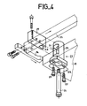
- These sliding connection devices 23 which are four in number in the example illustrated (FIG. 3) comprise (FIGS. 1a, 1b, 1c, 2, 4) each a sheath 25 fixed to the blank holder 19, a retaining screw with a stop head 24 fixed to the upper sole 18 of the tool, through this sheath 25 and a movable or retractable fork 26 engaging on this screw 24 between the head of the latter and the bottom of the sheath 25.
- the sheath 25 and the movable fork 26 respectively serve as the intervention withdrawal end-of-travel stop and the normal withdrawal end-of-travel stop.
- the sleeve or stop 25 is constituted by a part provided with a longitudinal section having the shape of an inverted elongated U with a drilled bottom for the sliding of the retaining screw with stop head 24, with side wall provided with a passage opening 31 for the fork 26, and with a free end provided with a retaining shoulder. These shoulders can be provided with holes for fixing screws 27.
- the sheath or stop 25 has a length greater than the thickness of the blank holder 19 so that when this sheath 25 is fixed by screws 27 on this clamp blank 19 through a corresponding hole 28 formed in the latter, the bottom of this stop 25 projects from the face of the blank holder opposite the fixing face, of a length equal to the thickness of the fork or stop retractable 26 increased by the thickness of the bottom of this sheath or stop 25.
- the retractable fork or stop 26 is constituted by a piece with two branches extended by a handle 29 which can be provided laterally with two wings 30 not shown. These wings 30 give the fork or stop 26 good stability in its movement during its retraction or its establishment.
- the fork or stop 26 slides on the surface of the blank holder 19 and enters the sheath or stop 25 through the passage opening 31 and its handle 29 made laterally protruding outside the sheath 25.
- the fork or stop 26 slides on the surface of the blank holder 19 and leaves the sheath or stop 25 through the passage opening 31.
- the four forks or stops 26 are fixed to the same control device 32 which communicates to them a simultaneous movement in their movement during their positioning or their retraction.
- This control device 32 comprises a front rod 33 and two sliding lateral tie rods 34, 35 to which the forks or stops are fixed 26.
- the frontal rod 33 is provided with handles 36 and the two tie rods 34, 35 are mounted sliding along the edges sides of the blank holder 19 according to a known technique.
- the forks or stops 26 are simultaneously inserted in the corresponding sleeves or stops 25 between the bottoms thereof and the heads d 'stop of the sliding retaining screw 24, and in this case the blank holder 19 has a normal working stroke and a normal withdrawal stroke.
- the punch 12, the die 5, the blank holder 19 and the sheet metal strip 20 respectively assume the positions represented in FIGS. 1a, 1b and 2 and at the end of a normal tool withdrawal stroke 1, in the sliding connection devices 23, the heads of the retaining screws 24 are stopped by the forks or stops 26, and in tool 1 the punch, matrix and blank holder have positions respectively partially illustrated in Figure lb.
- the forks or stops 26 are simultaneously retracted, that is to say withdrawn outside the sleeves or stops 25, using the control device 32, and in this case the blank holder 19 has a normal working stroke similar to that of normal operation of the tool 1 and an intervention withdrawal stroke illustrated in FIG. where the heads of the retaining screws 24 are stopped respectively by the bottoms of the sleeves or stops 25, and not by the forks or stops 26 which are already retracted or removed.
- the blank holder 19 moves away from the upper fixing sole 18 which carries the punch or punches, by a distance (FIG.
- the punch (s) 12 can thus be easily disassembled or removed at the same time as the die (s) 5 without requiring disassembly of the tool 1 outside the press to effect their change, replacement or maintenance.
- the tool 1 produced according to the invention thus makes it possible to avoid a waste of time and an additional cost of labor.
Landscapes
- Engineering & Computer Science (AREA)
- Mechanical Engineering (AREA)
- Mounting, Exchange, And Manufacturing Of Dies (AREA)
- Perforating, Stamping-Out Or Severing By Means Other Than Cutting (AREA)
- Press Drives And Press Lines (AREA)
- Punching Or Piercing (AREA)
Applications Claiming Priority (2)
| Application Number | Priority Date | Filing Date | Title |
|---|---|---|---|
| FR8417112 | 1984-11-09 | ||
| FR8417112A FR2572963B1 (fr) | 1984-11-09 | 1984-11-09 | Outil de presse a parties travaillantes demontables sous presse |
Publications (2)
| Publication Number | Publication Date |
|---|---|
| EP0181269A1 true EP0181269A1 (de) | 1986-05-14 |
| EP0181269B1 EP0181269B1 (de) | 1988-12-28 |
Family
ID=9309437
Family Applications (1)
| Application Number | Title | Priority Date | Filing Date |
|---|---|---|---|
| EP85402145A Expired EP0181269B1 (de) | 1984-11-09 | 1985-11-06 | Presswerkzeug mit unter der Presse abnehmbaren Werkteilen |
Country Status (8)
| Country | Link |
|---|---|
| US (1) | US4656902A (de) |
| EP (1) | EP0181269B1 (de) |
| JP (1) | JPH0613160B2 (de) |
| AU (1) | AU584686B2 (de) |
| CA (1) | CA1264420A (de) |
| DE (1) | DE3566960D1 (de) |
| ES (1) | ES8700986A1 (de) |
| FR (1) | FR2572963B1 (de) |
Cited By (3)
| Publication number | Priority date | Publication date | Assignee | Title |
|---|---|---|---|---|
| WO2000053357A1 (en) * | 1999-03-09 | 2000-09-14 | Dynacraft Industries Sdn. Bdh. | Precision stamping tool |
| CN102228942A (zh) * | 2011-04-27 | 2011-11-02 | 浙江大学 | 带自动脱模机构的半固态金属微触变成形装置 |
| EP2578329A4 (de) * | 2010-06-30 | 2013-08-14 | forward Zhang | Press- und ablösevorrichtung für eine stanzmatrize und druckstange dafür |
Families Citing this family (8)
| Publication number | Priority date | Publication date | Assignee | Title |
|---|---|---|---|---|
| CN103071730A (zh) * | 2013-01-30 | 2013-05-01 | 华一精密机械(昆山)有限公司 | 冲压成型标准件连续冲压模具 |
| CN103611821A (zh) * | 2013-12-10 | 2014-03-05 | 安徽江淮汽车股份有限公司 | 一种单人单机冲压生产模具结构 |
| CN104148469B (zh) * | 2014-06-30 | 2018-11-30 | 万盛兴精密技术(惠州)有限公司 | 一种快速成型模具制作装置及其制作方法 |
| CN104399819A (zh) * | 2014-11-28 | 2015-03-11 | 吴中区光福华宇钣金厂 | 一种新型钣金冲压模具 |
| CN105478589A (zh) * | 2015-11-30 | 2016-04-13 | 吴中区光福良盛机械厂 | 一种金属连接角级进模具的公模 |
| CN107971406B (zh) * | 2017-12-14 | 2024-02-06 | 安徽永舟文具有限公司 | 高精密保密型笔夹模具 |
| IT201900019421A1 (it) * | 2019-10-21 | 2021-04-21 | Salvagnini Italia Spa | Apparato di punzonatura |
| US11511331B2 (en) * | 2019-12-18 | 2022-11-29 | Express Products, Inc. | Die stacker |
Citations (4)
| Publication number | Priority date | Publication date | Assignee | Title |
|---|---|---|---|---|
| US3125917A (en) * | 1964-03-24 | Punch and die assembly having spaced tool positioning plates | ||
| US3673902A (en) * | 1970-02-09 | 1972-07-04 | Walter Strobel | Die set; fixture and method of making dies |
| US4103574A (en) * | 1974-08-01 | 1978-08-01 | Greer H William | Tool assembly, method of manufacture and components thereof |
| FR2413207A1 (fr) * | 1977-12-29 | 1979-07-27 | Cornercroft Eng Ltd | Dispositif de presse comprenant un ensemble elastique |
Family Cites Families (1)
| Publication number | Priority date | Publication date | Assignee | Title |
|---|---|---|---|---|
| US3140630A (en) * | 1960-10-31 | 1964-07-14 | Lewis H Wolf | Stripper spring unit for presses |
-
1984
- 1984-11-09 FR FR8417112A patent/FR2572963B1/fr not_active Expired
-
1985
- 1985-11-04 US US06/794,673 patent/US4656902A/en not_active Expired - Fee Related
- 1985-11-06 DE DE8585402145T patent/DE3566960D1/de not_active Expired
- 1985-11-06 EP EP85402145A patent/EP0181269B1/de not_active Expired
- 1985-11-08 ES ES548702A patent/ES8700986A1/es not_active Expired
- 1985-11-08 JP JP60250561A patent/JPH0613160B2/ja not_active Expired - Lifetime
- 1985-11-08 CA CA000494890A patent/CA1264420A/fr not_active Expired - Fee Related
-
1986
- 1986-03-21 AU AU54998/86A patent/AU584686B2/en not_active Ceased
Patent Citations (4)
| Publication number | Priority date | Publication date | Assignee | Title |
|---|---|---|---|---|
| US3125917A (en) * | 1964-03-24 | Punch and die assembly having spaced tool positioning plates | ||
| US3673902A (en) * | 1970-02-09 | 1972-07-04 | Walter Strobel | Die set; fixture and method of making dies |
| US4103574A (en) * | 1974-08-01 | 1978-08-01 | Greer H William | Tool assembly, method of manufacture and components thereof |
| FR2413207A1 (fr) * | 1977-12-29 | 1979-07-27 | Cornercroft Eng Ltd | Dispositif de presse comprenant un ensemble elastique |
Cited By (3)
| Publication number | Priority date | Publication date | Assignee | Title |
|---|---|---|---|---|
| WO2000053357A1 (en) * | 1999-03-09 | 2000-09-14 | Dynacraft Industries Sdn. Bdh. | Precision stamping tool |
| EP2578329A4 (de) * | 2010-06-30 | 2013-08-14 | forward Zhang | Press- und ablösevorrichtung für eine stanzmatrize und druckstange dafür |
| CN102228942A (zh) * | 2011-04-27 | 2011-11-02 | 浙江大学 | 带自动脱模机构的半固态金属微触变成形装置 |
Also Published As
| Publication number | Publication date |
|---|---|
| JPS61115700A (ja) | 1986-06-03 |
| AU5499886A (en) | 1987-09-24 |
| US4656902A (en) | 1987-04-14 |
| EP0181269B1 (de) | 1988-12-28 |
| FR2572963B1 (fr) | 1986-12-12 |
| ES8700986A1 (es) | 1986-11-16 |
| JPH0613160B2 (ja) | 1994-02-23 |
| CA1264420A (fr) | 1990-01-16 |
| AU584686B2 (en) | 1989-06-01 |
| DE3566960D1 (en) | 1989-02-02 |
| FR2572963A1 (fr) | 1986-05-16 |
| ES548702A0 (es) | 1986-11-16 |
Similar Documents
| Publication | Publication Date | Title |
|---|---|---|
| EP0181269B1 (de) | Presswerkzeug mit unter der Presse abnehmbaren Werkteilen | |
| DE2822476C2 (de) | Einrichtung zum Schneiden länglichen Profilmaterials, insbesondere von Rohrmaterial | |
| DE19635258C1 (de) | Bohr- und Fräswerk zum Verarbeiten von Werkstoffstangen | |
| DE4401610B4 (de) | Revolverstanzpresse | |
| DE3107436A1 (de) | "einrichtung an auflagetischen fuer werkzeugmaschinen zum ausrichten von grossformatigen streifen- oder plattenfoermigen werkstuecken" | |
| DE602004010334T2 (de) | Schlittengeführte Gehrungssäge | |
| FR2618706A1 (fr) | Dispositif de percage et rivetage | |
| EP0200622A1 (de) | Mit einem Führungs- und Auswerfsystem des Bandmetalls versehenes Presswerkzeug | |
| EP1543906A1 (de) | Bearbeitungseinheit zum Bearbeiten der Eckverbindungen von aus Profilstücken geschweissten Rahmen | |
| DE2837705A1 (de) | Metallbearbeitungsmaschine | |
| DE202017107270U1 (de) | Bedienfeld einer mechanischen Bearbeitungsvorrichtung für Stabmaterialien | |
| DE3411023C2 (de) | Vorrichtung zum Herstellen und/oder Bearbeiten von kaschierten Werkstücken | |
| WO2000003835A1 (de) | Werkzeugmaschine mit werkzeugauswechselvorrichtung | |
| FR2966370A1 (fr) | Outil a suivre pour presse et machine de faconnage associee | |
| DE1915570C3 (de) | Gieß- und Schmiedemaschine | |
| EP1561533B1 (de) | Vorrichtung zum Schneiden von Profilen | |
| DE3137819C2 (de) | Vorrichtung zum Abstechen von Schweißgraten | |
| US3059515A (en) | Broaching apparatus for machining grooves | |
| EP0196308A1 (de) | Ausstossermechanismus für exzenterpressen | |
| EP0243787B1 (de) | Transportsystem für den Umlauf von Pressscheiben und Matrizen an zum direkten und indirekten Pressen eingerichteten Strangpressen | |
| DE19525832C1 (de) | Rahmenbearbeitungsautomat | |
| EP0659538B1 (de) | Vorrichtung zum Anbringen von Henkeln an Behältern | |
| DE69413511T2 (de) | Vorrichtung zum Schneiden langer Produkte, insbesondere Rohren | |
| DE3241803C2 (de) | ||
| DE3416813C2 (de) |
Legal Events
| Date | Code | Title | Description |
|---|---|---|---|
| PUAI | Public reference made under article 153(3) epc to a published international application that has entered the european phase |
Free format text: ORIGINAL CODE: 0009012 |
|
| AK | Designated contracting states |
Kind code of ref document: A1 Designated state(s): CH DE FR GB IT LI SE |
|
| 17P | Request for examination filed |
Effective date: 19861011 |
|
| 17Q | First examination report despatched |
Effective date: 19871112 |
|
| GRAA | (expected) grant |
Free format text: ORIGINAL CODE: 0009210 |
|
| AK | Designated contracting states |
Kind code of ref document: B1 Designated state(s): CH DE FR GB IT LI SE |
|
| ITF | It: translation for a ep patent filed | ||
| REF | Corresponds to: |
Ref document number: 3566960 Country of ref document: DE Date of ref document: 19890202 |
|
| GBT | Gb: translation of ep patent filed (gb section 77(6)(a)/1977) | ||
| PLBE | No opposition filed within time limit |
Free format text: ORIGINAL CODE: 0009261 |
|
| STAA | Information on the status of an ep patent application or granted ep patent |
Free format text: STATUS: NO OPPOSITION FILED WITHIN TIME LIMIT |
|
| 26N | No opposition filed | ||
| PGFP | Annual fee paid to national office [announced via postgrant information from national office to epo] |
Ref country code: CH Payment date: 19921005 Year of fee payment: 8 |
|
| PGFP | Annual fee paid to national office [announced via postgrant information from national office to epo] |
Ref country code: DE Payment date: 19921009 Year of fee payment: 8 |
|
| PGFP | Annual fee paid to national office [announced via postgrant information from national office to epo] |
Ref country code: SE Payment date: 19921012 Year of fee payment: 8 |
|
| PGFP | Annual fee paid to national office [announced via postgrant information from national office to epo] |
Ref country code: GB Payment date: 19921014 Year of fee payment: 8 |
|
| ITTA | It: last paid annual fee | ||
| PG25 | Lapsed in a contracting state [announced via postgrant information from national office to epo] |
Ref country code: GB Effective date: 19931106 |
|
| PG25 | Lapsed in a contracting state [announced via postgrant information from national office to epo] |
Ref country code: SE Effective date: 19931107 |
|
| PG25 | Lapsed in a contracting state [announced via postgrant information from national office to epo] |
Ref country code: LI Effective date: 19931130 Ref country code: CH Effective date: 19931130 |
|
| GBPC | Gb: european patent ceased through non-payment of renewal fee |
Effective date: 19931106 |
|
| REG | Reference to a national code |
Ref country code: CH Ref legal event code: PL |
|
| PG25 | Lapsed in a contracting state [announced via postgrant information from national office to epo] |
Ref country code: DE Effective date: 19940802 |
|
| EUG | Se: european patent has lapsed |
Ref document number: 85402145.8 Effective date: 19940610 |
|
| PGFP | Annual fee paid to national office [announced via postgrant information from national office to epo] |
Ref country code: FR Payment date: 19961122 Year of fee payment: 12 |
|
| PG25 | Lapsed in a contracting state [announced via postgrant information from national office to epo] |
Ref country code: FR Free format text: THE PATENT HAS BEEN ANNULLED BY A DECISION OF A NATIONAL AUTHORITY Effective date: 19971130 |
|
| REG | Reference to a national code |
Ref country code: FR Ref legal event code: ST |