EP0181453A2 - Schneefräse - Google Patents
Schneefräse Download PDFInfo
- Publication number
- EP0181453A2 EP0181453A2 EP85111064A EP85111064A EP0181453A2 EP 0181453 A2 EP0181453 A2 EP 0181453A2 EP 85111064 A EP85111064 A EP 85111064A EP 85111064 A EP85111064 A EP 85111064A EP 0181453 A2 EP0181453 A2 EP 0181453A2
- Authority
- EP
- European Patent Office
- Prior art keywords
- ejection
- snow
- cup
- cups
- drum
- Prior art date
- Legal status (The legal status is an assumption and is not a legal conclusion. Google has not performed a legal analysis and makes no representation as to the accuracy of the status listed.)
- Granted
Links
Images
Classifications
-
- E—FIXED CONSTRUCTIONS
- E01—CONSTRUCTION OF ROADS, RAILWAYS, OR BRIDGES
- E01H—STREET CLEANING; CLEANING OF PERMANENT WAYS; CLEANING BEACHES; DISPERSING OR PREVENTING FOG IN GENERAL CLEANING STREET OR RAILWAY FURNITURE OR TUNNEL WALLS
- E01H5/00—Removing snow or ice from roads or like surfaces; Grading or roughening snow or ice
- E01H5/04—Apparatus propelled by animal or engine power; Apparatus propelled by hand with driven dislodging or conveying levelling elements, conveying pneumatically for the dislodged material
- E01H5/06—Apparatus propelled by animal or engine power; Apparatus propelled by hand with driven dislodging or conveying levelling elements, conveying pneumatically for the dislodged material dislodging essentially by non-driven elements, e.g. scraper blades, snow-plough blades, scoop blades
- E01H5/07—Apparatus propelled by animal or engine power; Apparatus propelled by hand with driven dislodging or conveying levelling elements, conveying pneumatically for the dislodged material dislodging essentially by non-driven elements, e.g. scraper blades, snow-plough blades, scoop blades and conveying dislodged material by driven or pneumatic means
- E01H5/076—Apparatus propelled by animal or engine power; Apparatus propelled by hand with driven dislodging or conveying levelling elements, conveying pneumatically for the dislodged material dislodging essentially by non-driven elements, e.g. scraper blades, snow-plough blades, scoop blades and conveying dislodged material by driven or pneumatic means by rotary or pneumatic conveying means, e.g. impeller wheels
-
- E—FIXED CONSTRUCTIONS
- E01—CONSTRUCTION OF ROADS, RAILWAYS, OR BRIDGES
- E01H—STREET CLEANING; CLEANING OF PERMANENT WAYS; CLEANING BEACHES; DISPERSING OR PREVENTING FOG IN GENERAL CLEANING STREET OR RAILWAY FURNITURE OR TUNNEL WALLS
- E01H5/00—Removing snow or ice from roads or like surfaces; Grading or roughening snow or ice
- E01H5/04—Apparatus propelled by animal or engine power; Apparatus propelled by hand with driven dislodging or conveying levelling elements, conveying pneumatically for the dislodged material
- E01H5/08—Apparatus propelled by animal or engine power; Apparatus propelled by hand with driven dislodging or conveying levelling elements, conveying pneumatically for the dislodged material dislodging essentially by driven elements
- E01H5/09—Apparatus propelled by animal or engine power; Apparatus propelled by hand with driven dislodging or conveying levelling elements, conveying pneumatically for the dislodged material dislodging essentially by driven elements the elements being rotary or moving along a closed circular path, e.g. rotary cutter, digging wheels
- E01H5/098—Apparatus propelled by animal or engine power; Apparatus propelled by hand with driven dislodging or conveying levelling elements, conveying pneumatically for the dislodged material dislodging essentially by driven elements the elements being rotary or moving along a closed circular path, e.g. rotary cutter, digging wheels about horizontal or substantially horizontal axises perpendicular or substantially perpendicular to the direction of clearing
Definitions
- the invention relates to a snow blower, the clearing member of which is designed as a drum lying transversely to the direction of movement, in which a number of cutting blades which run into an ejection cup and run obliquely to the drum axis are arranged on the drum periphery.
- a snow blower is a snow removal device which has a clearing rotor which is designed as a drum cutter-shaped drum arranged transversely to the direction of travel of the clearing device.
- a number of inclined cutting blades are arranged on the drum circumference and end at the end of the blade in an ejection cup.
- the drum On the side facing away from the space side, the drum is surrounded by a guide wall in which an ejection chimney is fastened, which is aligned with the ejection cups of the drum. If the drum is moved into a layer of snow, the snow is released from the snow bandage by the cutting blades, moved along the inclined blade walls in the direction of the discharge cups and flung into the discharge chute there.
- the profile of the cutting blades has a curvature with a small cutting angle, while the ejection cup has a wall that is essentially radial or only slightly inclined in the direction of rotation.
- All known snow blowers are designed in essentially the same way. Differences exist, for example, with regard to the number of ejection chimneys - snow blowers with one ejection chimney or two ejection chimneys are known - in the inclination and in the shape of the cutting blades and in the design of the ejection cups, the cup wall of which can be semicircular or polygonal. Furthermore, the milling drum can be followed by a centrifugal wheel into which the snow is conveyed by the ejection cups of the drum and which then takes over the ejection of the snow through an ejection chimney. In contrast to the snow blower, whose milling stream feeds the snow directly into the ejection chimney, this version is referred to as a milling blower.
- the cutting blades of the milling drum of a snow blower have to loosen large quantities from the snow bandage and convey them along the blades into the ejection cups from where the snow comes in the chute is thrown. It is unavoidable that because of the double function of the cutting blades and also the ejection cup, i.e. because of the cutting function on the one hand and because of the transport or ejection function on the other hand, the snow transport into the chute is disrupted. This is shown by the fact that not all of the detached snow gets into the chute, but a part is thrown out to the front and then has to be cleared a second time.
- a known snow blower (CH-PS 542 958) has a milling drum which is divided into two partial drums, the cutting blades being arranged on one partial drum and the ejection cups on the other partial drum. Since the partial drums have their own drives, the speed of the partial drums can be adapted to the different tasks of the cutting blades and the ejection cups, e.g. be enlarged. Nevertheless, the obstacle to snow transport in the area of the throwing cup is only slightly improved. For this, however, a relatively complicated and therefore complex drive and a greater power requirement must be accepted.
- At least one further ejection cup is arranged between two adjacent cutting blades in the region of the ejection cups.
- the further ejection cup is appropriately aligned with the ejection cups of the cutting blades.
- the effect of the further ejection cup can be improved in that it is provided with a cutting blade section which is shorter with respect to the length of the cutting blades.
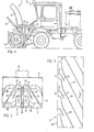
- Fig. 1 denotes a snow blower and 2 the push vehicle, on the front side of which the snow blower 1 is supported.
- the snow blower 1 has a rear wall 3, which extends on the bottom side around a rotating milling drum 4 and forms an upwardly inclined surface 5.
- a nozzle 6 is formed on the rear wall 3, on which a chute 8 is rotatably mounted.
- the rear wall 3 is supported by a lower strut 9 on the front chassis of the push vehicle 2 and by an upper strut 10 on a support frame 11.
- a hydraulic cylinder is also installed in the upper strut 10, by means of which the snow blower 1 can be tilted more or less forward.
- a lifting device 12 e.g.
- the milling drum 4 is rotatably mounted on the rear wall 3 and is driven by a drive unit 15 arranged on the push vehicle 2.
- a mechanical, hydraulic or electrical power transmission for driving the milling drum 4 is laid from the drive unit 15 (not shown).
- the drive of the milling drum 4 and the arrangement of the snow blower 1 on the push vehicle 2 are without for the invention Meaning, why the description of further details of the push vehicle 2 and the attachment of the snow blower 1 to the push vehicle 2 is omitted.
- the push vehicle 2 can be a motor vehicle of any kind, for example a tractor, caterpillar vehicle or truck.
- FIG. 2 shown front view of the milling drum 4 it can be seen that it consists of two sub-drums 16, 17, which are the same in mirror image.
- the partial drums 16, 17 have cutting blades 18 which extend obliquely over the surface of the drum and end in ejection cups 19.
- the cutting blades 18 with the ejection cups 19 extend over the entire width of one of the partial drums 16, 17.
- the snow released on the front from the snow bandage is conveyed along the cutting blades 18 into the ejection cups 19, through which the snow is thrown out through the ejection chimney 8 .
- the partial drums 16, 17 are each delimited by an end ring 20 on the inner edge. Two adjacent ejection cups 19 of the partial drums 16, 17 essentially form a single ejection cup which conveys the snow into the ejection chimney 8.
- the ejection cups of the partial drums 16, 17 can also be offset from one another.
- a further ejection cup 21 is fastened, which is aligned with the ejection cups 19 of the blades.
- the other ejection cups 21 can have the same shape as the ejection cups 19, but they can also be somewhat wider than the ejection cups 19.
- a cutting blade part 22 can be arranged at the end of the further ejection cups 21 on the cutting blade side are set, which, however, is much shorter than the length of the cutting blades 18th
- Fig. 3 the sub-drum 17 is shown in a developed form.
- the blades consisting of a cutting blade 18 and an ejection cup 19, can be seen, which extend over the entire width of the partial drum 17.
- the further ejection cup 21 with the cutting blade section 22 is arranged between two blades.
- the partial drum 17 is limited on the inside by the end ring 20.
- the further ejection cups 21 are not arranged in the middle of the two ejection cups 19, but rather closer to the ejection cup 19 which, seen in the direction of rotation of the milling drum, lies in front of the further ejection cup 21. It is also possible, not only one, but also two and more ejection cups 21 to be arranged between two ejection cups 19.
- the other ejection cups 21 was described on a snow blower, the milling drum of which conveys the snow into a single ejection chimney 8.
- the space between the two end rings 20 serves to transmit the drive power to the axis of the milling drum 4.
- the milling drum is formed from two partial drums which are of exactly the same design, but the ejection cups and thus the further ejection cups are not arranged on the edge of the milling drum, but in the middle of the same.
- a blade extending over the width of the partial drum therefore consists of two inclined cutting blades, between which there is an ejection cup.
- the other ejection cups accordingly have cutting blade sections on both sides.
- the other ejection cups can of course also be used later on the milling drums of existing snow blowers. For this purpose, either the existing drums are supplemented or replaced with new drums.
Landscapes
- Engineering & Computer Science (AREA)
- Architecture (AREA)
- Civil Engineering (AREA)
- Structural Engineering (AREA)
- Road Repair (AREA)
- Harvester Elements (AREA)
- Cleaning Of Streets, Tracks, Or Beaches (AREA)
- Soil Working Implements (AREA)
- Buildings Adapted To Withstand Abnormal External Influences (AREA)
- Materials Applied To Surfaces To Minimize Adherence Of Mist Or Water (AREA)
Abstract
Description
- Die Erfindung betrifft eine Schneefräse, deren Räumorgan als quer zur Bewegungsrichtung liegende Trommel ausgebildet ist, bei welcher an dem Trommelumfang eine Anzahl in einen Auswurfbecher auslaufende, schräg zur Trommelachse verlaufende Schneidschaufeln angeordnet sind.
- Als Schneefräse wird ein Schneeräumungsgerät bezeichnet, das einen Räumrotor aufweist, der als eine quer zur Fahrtrichtung des Räumgerätes angeordnete walzenfräserförmige Trommel ausgebildet ist. Am Trommelumfang sind eine Anzahl schrägverlaufender Schneidschaufeln angeordnet, die am Schaufel ende in einen Auswurfbecher auslaufen. Die Trommel ist auf der der Räumseite abgewandten Seite von einer Führungswand umgeben, in welcher ein Auswurfkamin befestigt ist, das mit den Auswurfbechern der Trommel fluchtet. Wird die Trommel in eine Schneeschicht bewegt, wird der Schnee durch die Schneidschaufeln aus dem Schneeverband gelöst, längs den schrägverlaufenden Schaufelwänden in Richtung der Auswurfbecher bewegt und dort in das Auswurfkamin geschleudert. Das Profil der Schneidschaufeln weist eine Wölbung mit einem kleinen Schneidwinkel auf, während der Auswurfbecher eine im wesentlichen radial verlaufende oder nur leicht in Drehrichtung geneigte Wand aufweist.
- Alle bekannten Schneefräsen sind im wesentlichen in gleicher Weise ausgebildet. Unterschiede bestehen beispielsweise bezüglich der Zahl der Auswurfkamine - es sind Schneefräsen mit einem Auswurfkamin oder zwei Auswurfkaminen bekannt -, in der Neigung und in der Form der Schneidschaufeln und in der Ausbildung der Auswurfbecher, deren Becherwand halbkreisförmig oder polygonförmig ausgebildet sein kann. Im weitern kann der Frästrommel ein Schleuderrad nachgeschaltet sein, in das der Schnee von den Auswurfbechern der Trommel gefördert wird und das dann den Auswurf des Schnees durch ein Auswurfkamin übernimmt. Diese Ausführung wird im Gegensatz zur Schneefräse, deren Frästromel den Schnee direkt in den Auswurfkamin fördert, als Frässchleuder bezeichnet.
- Im Gegensatz zum Fräswerkzeug für die Metallbearbeitung, bei dem nur ein mengenmässig geringer und praktisch kein gerichteter Materialtransport vorhanden ist, müssen die Schneidschaufeln der Frästrommel einer Schneefräse grosse Mengen aus dem Schneeverband lösen und diese längs der Schaufeln in die Auswurfbecher fördern, von wo der Schnee in das Auswurfkamin geschleudert wird. Es ist nicht zu vermeiden, dass wegen der Doppelfunktion der Schneidschaufeln und auch der Auswurfbecher, d.h. wegen der Schneidfunktion einerseits und wegen der Transport- bzw. Auswurffunktion andererseits, der Schneetransport in den Auswurfkamin gestört wird. Dies zeigt sich in der Weise, dass nicht der gesamte abgelöste Schnee in den Auswurfkamin gelangt, sondern ein Teil wieder nach vorne ausgeworfen wird und dann ein zweites Mal geräumt werden muss.
- Es hat nicht an Vorschlägen gefehlt, diesen Nachteil der Schneefräsen zu beheben oder mindestens zu verkleinern.
- So weist eine bekannte Schneefräse (CH-PS 542 958) eine Frästrommel auf, die in zwei Teiltrommeln unterteilt ist, wobei die Schneidschaufeln auf der einen Teiltrommel und die Auswurfbecher auf der andern Teiltrommel angeordnet sind. Da die Teiltrommeln eigene Antriebe aufweisen, kann die Drehzahl der Teiltrommeln den unterschiedlichen Aufgaben der Schneidschaufeln und der Auswurfbecher angepasst, z.B. vergrössert, werden. Trotzdem wird aber dadurch die Behinderung des Schneetransports im Bereich der Wurfbecher nur wenig verbessert. Dafür muss aber ein verhältnismässig komplizierter und dadurch aufwendiger Antrieb sowie ein grösserer Leistungsbedarf in Kauf genommen werden.
- Hier setzt die Erfindung ein, der die Aufgabe zugrundeliegt, eine Schneefräse der eingangs beschriebenen Art so auszugestalten, dass die Schneeführung im Bereich der Auswurfbecher verbessert und dadurch der Schneeauswurf nach vorne wesentlich vermindert und dadurcheine Leistungssteigerung erreicht wird.
- Diese Aufgabe wird gemäss der Erfindung dadurch gelöst, dass zwischen zwei benachbarten Schneidschaufeln im Bereich der Auswurfbecher mindestens ein weiterer Auswurfbecher angeordnet ist. Der weitere Auswurfbecher fluchtet hierbei zweckmäassig mit den Auswurfbechern der Schneidschaufeln. Die Wirkung des weiteren Auswurfbechers kann dadurch verbessert werden, dass er mit einer bezüglich der Länge der Schneidschaufeln kürzeren Schneidschaufelpartie versehen ist.
- Die Erfindung ist in der Zeichnung in einem Ausführungsbeispiel dargestellt und nachfolgend beschrieben.
- Es zeigen:
- Fig. 1 eine Seitenansicht einer Schneefräse, die an der Stirnseite eines Schubfahrzeuges befestigt ist,
- Fig. 2 eine Fronansicht der Frästrommel der Schneefräse nach Fig. 1 und
- Fig. 3 eine schematische Darstellung der Abwicklung einer Frästrommel.
- In Fig. 1 ist mit 1 eine Schneefräse und mit 2 das Schubfahrzeug bezeichnet, an dessen Stirnseite die Schneefräse 1 abgestützt ist. Die Schneefräse 1 weist eine Rückwand 3 auf, die sich bodenseitig um eine rotierende Frästrommel 4 erstreckt und eine nach oben gerichtete schräge Fläche 5 bildet. Im Bereich des Scheitels der Frästrommel 4 ist in der Rückwand 3 ein Stutzen 6 angeformt, auf dem ein Auswurfkamin 8 drehbar gelagert ist. Die Rückwand 3 ist mittels einer unteren Strebe 9 am vorderen Fahrgestell des Schubfahrzeugs 2 und mit einer oberen Strebe 10 an einem Tragrahmen 11 abgestützt. In der oberen Strebe 10 ist zudem ein Hydrozylinder eingebaut, mit Hilfe dessen die Schneefräse 1 mehr oder weniger nach vorwärts geneigt werden kann. Weiter ist am Tragrahmen 11 ein Hubgerät 12, z.B. ein Hydrozylinder, abgestützt, der zum Heben und Senken der Schneefräse 1 dient. Die Frästrommel 4 ist an der Rückwand 3 drehbar gelagert und wird von einem, auf dem Schubfahrzeug 2 angeordneten Antriebsaggregat 15 angetrieben. Vom Antriebsaggregat 15 ist eine mechanische, hydraulische oder elektrische Leistungsübertragung zum Antrieb der Frästrommel 4 verlegt (nicht dargestellt).
- Der Antrieb der Frästrommel 4 und die Anordnung der Schneefräse 1 am Schubfahrzeug 2 sind für die Erfindung ohne Bedeutung, weshalb die Schilderung von weiteren Details des Schubfahrzeuges 2 und der Befestigung der Schneefräse 1 am Schubfahrzeug 2 unterbleibt. Das Schubfahrzeug 2 kann ein Kraftfahrzeug beliebiger Art, z.B. ein Traktor, Raupenfahrzeug oder Lastwagen sein.
- Aus der in Fig'. 2 dargestellten Frontansicht der Frästrommel 4 ist ersichtlich, dass diese aus zwei Teiltrommeln 16, 17 besteht, die spiegelbildlich gleich sind. Die Teiltrommeln 16, 17 weisen Schneidschaufeln 18 auf, die sich schräg über die Oberfläche der Trommel erstrecken und in Auswurfbechern 19 auslaufen. Die Schneidschaufeln 18 mit den Auswurfbechern 19 erstrecken sich über die gesamte Breite einer der Teiltrommeln 16, 17. Der auf der Vorderseite aus dem Schneeverband gelöste Schnee wird längs der Schneidschaufeln 18 in die Auswurfbecher 19 gefördert, durch welche der Schnee durch das Auswurfkamin 8 ausgeschleudert wird.
- An dem Innenrand sind die Teiltrommeln 16, 17 durch je einen Endring 20 begrenzt. Je zwei nebeneinanderliegende Auswurfbecher 19 der Teiltrommeln 16, 17 bilden im wesentlichen einen einzigen Auswurfbecher, der den Schnee in das Auswurfkamin 8 fördert. Die Auswurfbecher der Teiltrommeln 16, 17 können aber auch zueinander versetzt sein.
- Zwischen zwei aus der Schneidschaufel 18 und dem Auswurfbecher 19 gebildeten Schaufeln ist ein weiterer Auswurfbecher 21 befestigt, der mit den Auswurfbechern 19 der Schaufeln fluchtet. Die weiteren Auswurfbecher 21 können dieselbe Form wie die Auswurfbecher 19 aufweisen, sie können jedoch auch etwas breiter sein als die Auswurfbecher 19. An dem schneidschaufelseitigen Ende der weiteren Auswurfbecher 21 kann eine Schneidschaufelpartie 22 angesetzt werden, die jedoch wesentlich kürzer ist als die Länge der Schneidschaufeln 18.
- Bei den bekannten Schneefräsen treten im Bereich der Schaufelbecher 19 Schneeverluste auf, die durch nach vorne austretenden Schnee sichtbar werden. Der nach vorne austretende Schnee wird auf die zu räumende Bahn geworfen und muss demnach nochmals geräumt werden. Durch Fangbleche wurde versucht, den austretenden Schnee abzufangen. Der Schnee wird zwar nicht mehr auf die zu räumende Bahn geworfen, die Verluste treten jedoch trotzdem auf.
- Es konnte nun überraschend festgestellt werden, dass durch den Einbau der weiteren Auswurfbecher 21, gegebenenfalls verbunden mit Schneeschaufelpartien 22, diese nach vorne austretenden Schneeverluste weitgehend vermieden werden können. Soweit festgestellt werden konnte, steht diese Verbesserung mit der Vergrösserung der Zahl der Auswurfbecher zusammen.
- In Fig. 3 ist die Teiltrommel 17 in abgewickelter Form dargestellt. Einerseits sind die sich aus einer Schneidschaufel 18 und einem Auswurfbecher 19 zusammensetzenden Schaufeln erkennbar, die sich über die gesamte Breite der Teiltrommel 17 erstrecken. Zwischen zwei Schaufeln ist der weitere Auswurfbecher 21 mit der Schneidschaufelpartie 22 angeordnet. Die Teiltrommel 17 wird in der Innenseite durch den Endring 20 begrenzt.
- Wie aus Fig. 3 erkennbar ist, sind die weiteren Auswurfbecher 21 nicht in der Mitte der beiden Auswurfbecher 19 angeordnet, sondern näher gegen denjenigen Auswurfbecher 19, der in der Drehrichtung der Frästrommel gesehen vor dem weiteren Auswurfbecher 21 liegt. Es ist auch möglich, nicht nur einen, sondern auch zwei und mehr Auswurfbecher 21 zwischen zwei Auswurfbechern 19 anzuordnen.
- Durch diese aussordentlich einfache Massnahme wird eine wesentliche Verbesserung des Schneetransportes durch die Frästrommel 4 erreicht.
- Die Wirkung der weiteren Auswurfbecher 21 wurde an einer Schneefräse beschrieben, deren Frästrommel den Schnee in einen einzigen Auswurfkamin 8 fördert. Der Zwischenraum zwischen den beiden Endringen 20 dient dazu, die Antriebsleistung auf die Achse der Frästrommel 4 zu übertragen. Es ist jedoch auch möglich, die weiteren Auswurfbecher 21 bei einer Schneefräse anzubrignen, die mit zwei Auswurfkaminen ausgerüstet ist. Auch in diesem Fall ist die Frästrommel aus zwei Teiltrommeln gebildet, die genau gleich ausgebildet sind, wobei jedoch die Auswurfbecher und damit die weiteren Auswurfbecher nicht am Rand der Frästrommel, sondern in der Mitte derselben angeordnet sind. Eine sich über die Teiltrommelbreite erstreckende Schaufel besteht demnach aus zwei schrägverlaufenden Schneidschaufeln, zwischen denen ein Auswurfbecher liegt. Die weiteren Auswurfbecher weisen dementsprechend auf beiden Seiten Schneidschaufelpartien auf. Die weiteren Auswurfbecher können natürlich auch nachträglich an Frästrommeln bestehender Schneefräsen verwendet werden. Es werden hierzu entweder die bestehenden Trommeln ergänzt oder durch neue Trommeln ersetzt.
Claims (6)
Priority Applications (1)
| Application Number | Priority Date | Filing Date | Title |
|---|---|---|---|
| AT85111064T ATE50013T1 (de) | 1984-11-05 | 1985-09-02 | Schneefraese. |
Applications Claiming Priority (2)
| Application Number | Priority Date | Filing Date | Title |
|---|---|---|---|
| CH5298/84 | 1984-11-05 | ||
| CH5298/84A CH664180A5 (de) | 1984-11-05 | 1984-11-05 | Schneefraese. |
Publications (3)
| Publication Number | Publication Date |
|---|---|
| EP0181453A2 true EP0181453A2 (de) | 1986-05-21 |
| EP0181453A3 EP0181453A3 (en) | 1987-05-13 |
| EP0181453B1 EP0181453B1 (de) | 1990-01-31 |
Family
ID=4291249
Family Applications (1)
| Application Number | Title | Priority Date | Filing Date |
|---|---|---|---|
| EP85111064A Expired - Lifetime EP0181453B1 (de) | 1984-11-05 | 1985-09-02 | Schneefräse |
Country Status (4)
| Country | Link |
|---|---|
| EP (1) | EP0181453B1 (de) |
| AT (1) | ATE50013T1 (de) |
| CH (1) | CH664180A5 (de) |
| DE (1) | DE3575753D1 (de) |
Family Cites Families (4)
| Publication number | Priority date | Publication date | Assignee | Title |
|---|---|---|---|---|
| DE1910440A1 (de) * | 1968-05-16 | 1969-11-27 | Peitl Gmbh J | Schneeraeummaschine,wie Schneckenschneeschleuder,Schneckenfraese od.dgl.,mit quer zur Fortbewegungsrichtung liegender Zubringer- oder Fraesschnecke und in Fortbewegungsrichtung liegendem Wurfwerk |
| CH542958A (de) * | 1970-08-19 | 1973-10-15 | Boschung Fa M | Schneefräse |
| DE2147001C3 (de) * | 1971-09-21 | 1974-11-21 | Ing. Alfred Schmidt Gmbh, 7822 St. Blasien | Schneefräse mit mindestens einer im Inneren der Frästrommel angeordneten Antriebseinheit |
| US3908540A (en) * | 1972-10-20 | 1975-09-30 | Sno Pac Corp | Mobile compacting apparatus |
-
1984
- 1984-11-05 CH CH5298/84A patent/CH664180A5/de not_active IP Right Cessation
-
1985
- 1985-09-02 EP EP85111064A patent/EP0181453B1/de not_active Expired - Lifetime
- 1985-09-02 DE DE8585111064T patent/DE3575753D1/de not_active Expired - Lifetime
- 1985-09-02 AT AT85111064T patent/ATE50013T1/de not_active IP Right Cessation
Also Published As
| Publication number | Publication date |
|---|---|
| DE3575753D1 (de) | 1990-03-08 |
| EP0181453B1 (de) | 1990-01-31 |
| ATE50013T1 (de) | 1990-02-15 |
| EP0181453A3 (en) | 1987-05-13 |
| CH664180A5 (de) | 1988-02-15 |
Similar Documents
| Publication | Publication Date | Title |
|---|---|---|
| DE1295909B (de) | Maehmaschine | |
| DE1923780A1 (de) | Geblaese fuer die Reinigungsvorrichtung eines Maehdreschers | |
| DE2252105A1 (de) | Maehdrescher | |
| DE2440650C2 (de) | Schaufelradlader | |
| DE2843782C2 (de) | Kreiselheuwerbungsmaschine zum Schwadenlegen oder Schwadenwenden oder zum Zetten/Wenden | |
| DE2929256A1 (de) | Schleppkopf fuer saugbagger | |
| DE29719508U1 (de) | Anbau-Kehrvorrichtung mit Aufnahmeeinrichtung | |
| EP0181453B1 (de) | Schneefräse | |
| EP1330951B1 (de) | Futtermischer | |
| DE19949678A1 (de) | Bodenfräse zur Nivellierung von Flächen | |
| DE2330257C2 (de) | Selbstfahrender Feldhäcksler | |
| DE2805593C2 (de) | Vorrichtung mit einer motorisch angetriebenen, um eine Achse rotierenden und messerartige Grabwerkzeuge aufweisenden Fräse | |
| EP0132012B1 (de) | Mähmaschine | |
| WO2004026018A1 (de) | Scheibenegge | |
| DE1482177C3 (de) | Heuwerbungsmaschine | |
| EP0346725B1 (de) | Maschine zum Ernten von Wurzelfrüchten, insbesondere Zuckerrüben | |
| DE2528418A1 (de) | Vorrichtung zum schneiden von nuten, insbesondere in strassenbelaege | |
| DE3013544A1 (de) | Graslader zum anbau an maehgeraete | |
| DE2808887C2 (de) | ||
| DE1534159A1 (de) | Schneeraeummaschine | |
| DE4006236A1 (de) | Vorrichtung zum abtragen von wenigstens unter lagerdruck zusammengepresstem foerdergut aus einem futterstock, silo oder presskoerper | |
| DE1757691A1 (de) | Kreiselmaeher | |
| DE1759826C3 (de) | Schneeräummaschine | |
| DE930715C (de) | Vorrichtung zum Reinigen und Offenhalten von Graeben, insbesondere Entwaesserungsgraeben | |
| DE3122200C2 (de) | Schneid- und Aufdeckvorrichtung für den Hopfenbau |
Legal Events
| Date | Code | Title | Description |
|---|---|---|---|
| PUAI | Public reference made under article 153(3) epc to a published international application that has entered the european phase |
Free format text: ORIGINAL CODE: 0009012 |
|
| AK | Designated contracting states |
Kind code of ref document: A2 Designated state(s): AT DE FR IT |
|
| PUAL | Search report despatched |
Free format text: ORIGINAL CODE: 0009013 |
|
| AK | Designated contracting states |
Kind code of ref document: A3 Designated state(s): AT DE FR IT |
|
| 17P | Request for examination filed |
Effective date: 19871021 |
|
| 17Q | First examination report despatched |
Effective date: 19890310 |
|
| GRAA | (expected) grant |
Free format text: ORIGINAL CODE: 0009210 |
|
| AK | Designated contracting states |
Kind code of ref document: B1 Designated state(s): AT DE FR IT |
|
| REF | Corresponds to: |
Ref document number: 50013 Country of ref document: AT Date of ref document: 19900215 Kind code of ref document: T |
|
| REF | Corresponds to: |
Ref document number: 3575753 Country of ref document: DE Date of ref document: 19900308 |
|
| ET | Fr: translation filed | ||
| ITF | It: translation for a ep patent filed | ||
| PLBE | No opposition filed within time limit |
Free format text: ORIGINAL CODE: 0009261 |
|
| STAA | Information on the status of an ep patent application or granted ep patent |
Free format text: STATUS: NO OPPOSITION FILED WITHIN TIME LIMIT |
|
| 26N | No opposition filed | ||
| PGFP | Annual fee paid to national office [announced via postgrant information from national office to epo] |
Ref country code: DE Payment date: 19930811 Year of fee payment: 9 |
|
| PGFP | Annual fee paid to national office [announced via postgrant information from national office to epo] |
Ref country code: FR Payment date: 19930812 Year of fee payment: 9 |
|
| PGFP | Annual fee paid to national office [announced via postgrant information from national office to epo] |
Ref country code: AT Payment date: 19930820 Year of fee payment: 9 |
|
| ITTA | It: last paid annual fee | ||
| PG25 | Lapsed in a contracting state [announced via postgrant information from national office to epo] |
Ref country code: AT Effective date: 19940902 |
|
| PG25 | Lapsed in a contracting state [announced via postgrant information from national office to epo] |
Ref country code: FR Effective date: 19950531 |
|
| PG25 | Lapsed in a contracting state [announced via postgrant information from national office to epo] |
Ref country code: DE Effective date: 19950601 |
|
| REG | Reference to a national code |
Ref country code: FR Ref legal event code: ST |