EP0181453A2 - Fraise à neige - Google Patents
Fraise à neige Download PDFInfo
- Publication number
- EP0181453A2 EP0181453A2 EP85111064A EP85111064A EP0181453A2 EP 0181453 A2 EP0181453 A2 EP 0181453A2 EP 85111064 A EP85111064 A EP 85111064A EP 85111064 A EP85111064 A EP 85111064A EP 0181453 A2 EP0181453 A2 EP 0181453A2
- Authority
- EP
- European Patent Office
- Prior art keywords
- ejection
- snow
- cup
- cups
- drum
- Prior art date
- Legal status (The legal status is an assumption and is not a legal conclusion. Google has not performed a legal analysis and makes no representation as to the accuracy of the status listed.)
- Granted
Links
Images
Classifications
-
- E—FIXED CONSTRUCTIONS
- E01—CONSTRUCTION OF ROADS, RAILWAYS, OR BRIDGES
- E01H—STREET CLEANING; CLEANING OF PERMANENT WAYS; CLEANING BEACHES; DISPERSING OR PREVENTING FOG IN GENERAL CLEANING STREET OR RAILWAY FURNITURE OR TUNNEL WALLS
- E01H5/00—Removing snow or ice from roads or like surfaces; Grading or roughening snow or ice
- E01H5/04—Apparatus propelled by animal or engine power; Apparatus propelled by hand with driven dislodging or conveying levelling elements, conveying pneumatically for the dislodged material
- E01H5/06—Apparatus propelled by animal or engine power; Apparatus propelled by hand with driven dislodging or conveying levelling elements, conveying pneumatically for the dislodged material dislodging essentially by non-driven elements, e.g. scraper blades, snow-plough blades, scoop blades
- E01H5/07—Apparatus propelled by animal or engine power; Apparatus propelled by hand with driven dislodging or conveying levelling elements, conveying pneumatically for the dislodged material dislodging essentially by non-driven elements, e.g. scraper blades, snow-plough blades, scoop blades and conveying dislodged material by driven or pneumatic means
- E01H5/076—Apparatus propelled by animal or engine power; Apparatus propelled by hand with driven dislodging or conveying levelling elements, conveying pneumatically for the dislodged material dislodging essentially by non-driven elements, e.g. scraper blades, snow-plough blades, scoop blades and conveying dislodged material by driven or pneumatic means by rotary or pneumatic conveying means, e.g. impeller wheels
-
- E—FIXED CONSTRUCTIONS
- E01—CONSTRUCTION OF ROADS, RAILWAYS, OR BRIDGES
- E01H—STREET CLEANING; CLEANING OF PERMANENT WAYS; CLEANING BEACHES; DISPERSING OR PREVENTING FOG IN GENERAL CLEANING STREET OR RAILWAY FURNITURE OR TUNNEL WALLS
- E01H5/00—Removing snow or ice from roads or like surfaces; Grading or roughening snow or ice
- E01H5/04—Apparatus propelled by animal or engine power; Apparatus propelled by hand with driven dislodging or conveying levelling elements, conveying pneumatically for the dislodged material
- E01H5/08—Apparatus propelled by animal or engine power; Apparatus propelled by hand with driven dislodging or conveying levelling elements, conveying pneumatically for the dislodged material dislodging essentially by driven elements
- E01H5/09—Apparatus propelled by animal or engine power; Apparatus propelled by hand with driven dislodging or conveying levelling elements, conveying pneumatically for the dislodged material dislodging essentially by driven elements the elements being rotary or moving along a closed circular path, e.g. rotary cutter, digging wheels
- E01H5/098—Apparatus propelled by animal or engine power; Apparatus propelled by hand with driven dislodging or conveying levelling elements, conveying pneumatically for the dislodged material dislodging essentially by driven elements the elements being rotary or moving along a closed circular path, e.g. rotary cutter, digging wheels about horizontal or substantially horizontal axises perpendicular or substantially perpendicular to the direction of clearing
Definitions
- the invention relates to a snow blower, the clearing member of which is designed as a drum lying transversely to the direction of movement, in which a number of cutting blades which run into an ejection cup and run obliquely to the drum axis are arranged on the drum periphery.
- a snow blower is a snow removal device which has a clearing rotor which is designed as a drum cutter-shaped drum arranged transversely to the direction of travel of the clearing device.
- a number of inclined cutting blades are arranged on the drum circumference and end at the end of the blade in an ejection cup.
- the drum On the side facing away from the space side, the drum is surrounded by a guide wall in which an ejection chimney is fastened, which is aligned with the ejection cups of the drum. If the drum is moved into a layer of snow, the snow is released from the snow bandage by the cutting blades, moved along the inclined blade walls in the direction of the discharge cups and flung into the discharge chute there.
- the profile of the cutting blades has a curvature with a small cutting angle, while the ejection cup has a wall that is essentially radial or only slightly inclined in the direction of rotation.
- All known snow blowers are designed in essentially the same way. Differences exist, for example, with regard to the number of ejection chimneys - snow blowers with one ejection chimney or two ejection chimneys are known - in the inclination and in the shape of the cutting blades and in the design of the ejection cups, the cup wall of which can be semicircular or polygonal. Furthermore, the milling drum can be followed by a centrifugal wheel into which the snow is conveyed by the ejection cups of the drum and which then takes over the ejection of the snow through an ejection chimney. In contrast to the snow blower, whose milling stream feeds the snow directly into the ejection chimney, this version is referred to as a milling blower.
- the cutting blades of the milling drum of a snow blower have to loosen large quantities from the snow bandage and convey them along the blades into the ejection cups from where the snow comes in the chute is thrown. It is unavoidable that because of the double function of the cutting blades and also the ejection cup, i.e. because of the cutting function on the one hand and because of the transport or ejection function on the other hand, the snow transport into the chute is disrupted. This is shown by the fact that not all of the detached snow gets into the chute, but a part is thrown out to the front and then has to be cleared a second time.
- a known snow blower (CH-PS 542 958) has a milling drum which is divided into two partial drums, the cutting blades being arranged on one partial drum and the ejection cups on the other partial drum. Since the partial drums have their own drives, the speed of the partial drums can be adapted to the different tasks of the cutting blades and the ejection cups, e.g. be enlarged. Nevertheless, the obstacle to snow transport in the area of the throwing cup is only slightly improved. For this, however, a relatively complicated and therefore complex drive and a greater power requirement must be accepted.
- At least one further ejection cup is arranged between two adjacent cutting blades in the region of the ejection cups.
- the further ejection cup is appropriately aligned with the ejection cups of the cutting blades.
- the effect of the further ejection cup can be improved in that it is provided with a cutting blade section which is shorter with respect to the length of the cutting blades.
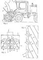
- Fig. 1 denotes a snow blower and 2 the push vehicle, on the front side of which the snow blower 1 is supported.
- the snow blower 1 has a rear wall 3, which extends on the bottom side around a rotating milling drum 4 and forms an upwardly inclined surface 5.
- a nozzle 6 is formed on the rear wall 3, on which a chute 8 is rotatably mounted.
- the rear wall 3 is supported by a lower strut 9 on the front chassis of the push vehicle 2 and by an upper strut 10 on a support frame 11.
- a hydraulic cylinder is also installed in the upper strut 10, by means of which the snow blower 1 can be tilted more or less forward.
- a lifting device 12 e.g.
- the milling drum 4 is rotatably mounted on the rear wall 3 and is driven by a drive unit 15 arranged on the push vehicle 2.
- a mechanical, hydraulic or electrical power transmission for driving the milling drum 4 is laid from the drive unit 15 (not shown).
- the drive of the milling drum 4 and the arrangement of the snow blower 1 on the push vehicle 2 are without for the invention Meaning, why the description of further details of the push vehicle 2 and the attachment of the snow blower 1 to the push vehicle 2 is omitted.
- the push vehicle 2 can be a motor vehicle of any kind, for example a tractor, caterpillar vehicle or truck.
- FIG. 2 shown front view of the milling drum 4 it can be seen that it consists of two sub-drums 16, 17, which are the same in mirror image.
- the partial drums 16, 17 have cutting blades 18 which extend obliquely over the surface of the drum and end in ejection cups 19.
- the cutting blades 18 with the ejection cups 19 extend over the entire width of one of the partial drums 16, 17.
- the snow released on the front from the snow bandage is conveyed along the cutting blades 18 into the ejection cups 19, through which the snow is thrown out through the ejection chimney 8 .
- the partial drums 16, 17 are each delimited by an end ring 20 on the inner edge. Two adjacent ejection cups 19 of the partial drums 16, 17 essentially form a single ejection cup which conveys the snow into the ejection chimney 8.
- the ejection cups of the partial drums 16, 17 can also be offset from one another.
- a further ejection cup 21 is fastened, which is aligned with the ejection cups 19 of the blades.
- the other ejection cups 21 can have the same shape as the ejection cups 19, but they can also be somewhat wider than the ejection cups 19.
- a cutting blade part 22 can be arranged at the end of the further ejection cups 21 on the cutting blade side are set, which, however, is much shorter than the length of the cutting blades 18th
- Fig. 3 the sub-drum 17 is shown in a developed form.
- the blades consisting of a cutting blade 18 and an ejection cup 19, can be seen, which extend over the entire width of the partial drum 17.
- the further ejection cup 21 with the cutting blade section 22 is arranged between two blades.
- the partial drum 17 is limited on the inside by the end ring 20.
- the further ejection cups 21 are not arranged in the middle of the two ejection cups 19, but rather closer to the ejection cup 19 which, seen in the direction of rotation of the milling drum, lies in front of the further ejection cup 21. It is also possible, not only one, but also two and more ejection cups 21 to be arranged between two ejection cups 19.
- the other ejection cups 21 was described on a snow blower, the milling drum of which conveys the snow into a single ejection chimney 8.
- the space between the two end rings 20 serves to transmit the drive power to the axis of the milling drum 4.
- the milling drum is formed from two partial drums which are of exactly the same design, but the ejection cups and thus the further ejection cups are not arranged on the edge of the milling drum, but in the middle of the same.
- a blade extending over the width of the partial drum therefore consists of two inclined cutting blades, between which there is an ejection cup.
- the other ejection cups accordingly have cutting blade sections on both sides.
- the other ejection cups can of course also be used later on the milling drums of existing snow blowers. For this purpose, either the existing drums are supplemented or replaced with new drums.
Landscapes
- Engineering & Computer Science (AREA)
- Architecture (AREA)
- Civil Engineering (AREA)
- Structural Engineering (AREA)
- Road Repair (AREA)
- Harvester Elements (AREA)
- Buildings Adapted To Withstand Abnormal External Influences (AREA)
- Materials Applied To Surfaces To Minimize Adherence Of Mist Or Water (AREA)
- Cleaning Of Streets, Tracks, Or Beaches (AREA)
- Soil Working Implements (AREA)
Priority Applications (1)
| Application Number | Priority Date | Filing Date | Title |
|---|---|---|---|
| AT85111064T ATE50013T1 (de) | 1984-11-05 | 1985-09-02 | Schneefraese. |
Applications Claiming Priority (2)
| Application Number | Priority Date | Filing Date | Title |
|---|---|---|---|
| CH5298/84 | 1984-11-05 | ||
| CH5298/84A CH664180A5 (de) | 1984-11-05 | 1984-11-05 | Schneefraese. |
Publications (3)
| Publication Number | Publication Date |
|---|---|
| EP0181453A2 true EP0181453A2 (fr) | 1986-05-21 |
| EP0181453A3 EP0181453A3 (en) | 1987-05-13 |
| EP0181453B1 EP0181453B1 (fr) | 1990-01-31 |
Family
ID=4291249
Family Applications (1)
| Application Number | Title | Priority Date | Filing Date |
|---|---|---|---|
| EP85111064A Expired - Lifetime EP0181453B1 (fr) | 1984-11-05 | 1985-09-02 | Fraise à neige |
Country Status (4)
| Country | Link |
|---|---|
| EP (1) | EP0181453B1 (fr) |
| AT (1) | ATE50013T1 (fr) |
| CH (1) | CH664180A5 (fr) |
| DE (1) | DE3575753D1 (fr) |
Family Cites Families (4)
| Publication number | Priority date | Publication date | Assignee | Title |
|---|---|---|---|---|
| DE1910440A1 (de) * | 1968-05-16 | 1969-11-27 | Peitl Gmbh J | Schneeraeummaschine,wie Schneckenschneeschleuder,Schneckenfraese od.dgl.,mit quer zur Fortbewegungsrichtung liegender Zubringer- oder Fraesschnecke und in Fortbewegungsrichtung liegendem Wurfwerk |
| CH542958A (de) * | 1970-08-19 | 1973-10-15 | Boschung Fa M | Schneefräse |
| DE2147001C3 (de) * | 1971-09-21 | 1974-11-21 | Ing. Alfred Schmidt Gmbh, 7822 St. Blasien | Schneefräse mit mindestens einer im Inneren der Frästrommel angeordneten Antriebseinheit |
| US3908540A (en) * | 1972-10-20 | 1975-09-30 | Sno Pac Corp | Mobile compacting apparatus |
-
1984
- 1984-11-05 CH CH5298/84A patent/CH664180A5/de not_active IP Right Cessation
-
1985
- 1985-09-02 AT AT85111064T patent/ATE50013T1/de not_active IP Right Cessation
- 1985-09-02 EP EP85111064A patent/EP0181453B1/fr not_active Expired - Lifetime
- 1985-09-02 DE DE8585111064T patent/DE3575753D1/de not_active Expired - Lifetime
Also Published As
| Publication number | Publication date |
|---|---|
| ATE50013T1 (de) | 1990-02-15 |
| CH664180A5 (de) | 1988-02-15 |
| DE3575753D1 (de) | 1990-03-08 |
| EP0181453B1 (fr) | 1990-01-31 |
| EP0181453A3 (en) | 1987-05-13 |
Similar Documents
| Publication | Publication Date | Title |
|---|---|---|
| DE2849915C2 (de) | Mähzetter | |
| DE1295909B (de) | Maehmaschine | |
| EP2835471B2 (fr) | Fraiseuse routière et procédé de fraisage et de transport du flux de matériau fraisé | |
| DE1923780A1 (de) | Geblaese fuer die Reinigungsvorrichtung eines Maehdreschers | |
| DE2252105A1 (de) | Maehdrescher | |
| DE2440650C2 (de) | Schaufelradlader | |
| DE2843782C2 (de) | Kreiselheuwerbungsmaschine zum Schwadenlegen oder Schwadenwenden oder zum Zetten/Wenden | |
| DE2929256A1 (de) | Schleppkopf fuer saugbagger | |
| DE29719508U1 (de) | Anbau-Kehrvorrichtung mit Aufnahmeeinrichtung | |
| EP0181453B1 (fr) | Fraise à neige | |
| EP1330951B1 (fr) | Appareil mélangeur de fourrage | |
| CH618837A5 (en) | Machine for turning over compost heaps | |
| DE19949678A1 (de) | Bodenfräse zur Nivellierung von Flächen | |
| DE2330257C2 (de) | Selbstfahrender Feldhäcksler | |
| DE2805593C2 (de) | Vorrichtung mit einer motorisch angetriebenen, um eine Achse rotierenden und messerartige Grabwerkzeuge aufweisenden Fräse | |
| EP0132012B1 (fr) | Faucheuse | |
| WO2004026018A1 (fr) | Pulverisateur a disques | |
| DE7018452U (de) | Kreiselschwadrechen. | |
| EP0187164A2 (fr) | Récolteuse de betteraves | |
| DE1482177C3 (de) | Heuwerbungsmaschine | |
| EP0346725B1 (fr) | Machine pour la récolte des betteraves, en particulier des betteraves sucrières | |
| DE2528418A1 (de) | Vorrichtung zum schneiden von nuten, insbesondere in strassenbelaege | |
| DE3013544A1 (de) | Graslader zum anbau an maehgeraete | |
| DE2808887C2 (fr) | ||
| DE1534159A1 (de) | Schneeraeummaschine |
Legal Events
| Date | Code | Title | Description |
|---|---|---|---|
| PUAI | Public reference made under article 153(3) epc to a published international application that has entered the european phase |
Free format text: ORIGINAL CODE: 0009012 |
|
| AK | Designated contracting states |
Kind code of ref document: A2 Designated state(s): AT DE FR IT |
|
| PUAL | Search report despatched |
Free format text: ORIGINAL CODE: 0009013 |
|
| AK | Designated contracting states |
Kind code of ref document: A3 Designated state(s): AT DE FR IT |
|
| 17P | Request for examination filed |
Effective date: 19871021 |
|
| 17Q | First examination report despatched |
Effective date: 19890310 |
|
| GRAA | (expected) grant |
Free format text: ORIGINAL CODE: 0009210 |
|
| AK | Designated contracting states |
Kind code of ref document: B1 Designated state(s): AT DE FR IT |
|
| REF | Corresponds to: |
Ref document number: 50013 Country of ref document: AT Date of ref document: 19900215 Kind code of ref document: T |
|
| REF | Corresponds to: |
Ref document number: 3575753 Country of ref document: DE Date of ref document: 19900308 |
|
| ET | Fr: translation filed | ||
| ITF | It: translation for a ep patent filed | ||
| PLBE | No opposition filed within time limit |
Free format text: ORIGINAL CODE: 0009261 |
|
| STAA | Information on the status of an ep patent application or granted ep patent |
Free format text: STATUS: NO OPPOSITION FILED WITHIN TIME LIMIT |
|
| 26N | No opposition filed | ||
| PGFP | Annual fee paid to national office [announced via postgrant information from national office to epo] |
Ref country code: DE Payment date: 19930811 Year of fee payment: 9 |
|
| PGFP | Annual fee paid to national office [announced via postgrant information from national office to epo] |
Ref country code: FR Payment date: 19930812 Year of fee payment: 9 |
|
| PGFP | Annual fee paid to national office [announced via postgrant information from national office to epo] |
Ref country code: AT Payment date: 19930820 Year of fee payment: 9 |
|
| ITTA | It: last paid annual fee | ||
| PG25 | Lapsed in a contracting state [announced via postgrant information from national office to epo] |
Ref country code: AT Effective date: 19940902 |
|
| PG25 | Lapsed in a contracting state [announced via postgrant information from national office to epo] |
Ref country code: FR Effective date: 19950531 |
|
| PG25 | Lapsed in a contracting state [announced via postgrant information from national office to epo] |
Ref country code: DE Effective date: 19950601 |
|
| REG | Reference to a national code |
Ref country code: FR Ref legal event code: ST |