EP0181467B1 - Capteur différentiel - Google Patents
Capteur différentiel Download PDFInfo
- Publication number
- EP0181467B1 EP0181467B1 EP85111918A EP85111918A EP0181467B1 EP 0181467 B1 EP0181467 B1 EP 0181467B1 EP 85111918 A EP85111918 A EP 85111918A EP 85111918 A EP85111918 A EP 85111918A EP 0181467 B1 EP0181467 B1 EP 0181467B1
- Authority
- EP
- European Patent Office
- Prior art keywords
- voltage
- resistors
- current source
- sensor
- magnetic field
- Prior art date
- Legal status (The legal status is an assumption and is not a legal conclusion. Google has not performed a legal analysis and makes no representation as to the accuracy of the status listed.)
- Expired - Lifetime
Links
- 239000000523 sample Substances 0.000 title 1
- 230000001419 dependent effect Effects 0.000 claims description 5
- 238000010586 diagram Methods 0.000 description 2
- 230000009977 dual effect Effects 0.000 description 1
- 238000011156 evaluation Methods 0.000 description 1
- 230000004907 flux Effects 0.000 description 1
- 230000001105 regulatory effect Effects 0.000 description 1
- 239000000758 substrate Substances 0.000 description 1
- 229910000859 α-Fe Inorganic materials 0.000 description 1
Images
Classifications
-
- G—PHYSICS
- G01—MEASURING; TESTING
- G01D—MEASURING NOT SPECIALLY ADAPTED FOR A SPECIFIC VARIABLE; ARRANGEMENTS FOR MEASURING TWO OR MORE VARIABLES NOT COVERED IN A SINGLE OTHER SUBCLASS; TARIFF METERING APPARATUS; MEASURING OR TESTING NOT OTHERWISE PROVIDED FOR
- G01D5/00—Mechanical means for transferring the output of a sensing member; Means for converting the output of a sensing member to another variable where the form or nature of the sensing member does not constrain the means for converting; Transducers not specially adapted for a specific variable
- G01D5/12—Mechanical means for transferring the output of a sensing member; Means for converting the output of a sensing member to another variable where the form or nature of the sensing member does not constrain the means for converting; Transducers not specially adapted for a specific variable using electric or magnetic means
- G01D5/14—Mechanical means for transferring the output of a sensing member; Means for converting the output of a sensing member to another variable where the form or nature of the sensing member does not constrain the means for converting; Transducers not specially adapted for a specific variable using electric or magnetic means influencing the magnitude of a current or voltage
- G01D5/142—Mechanical means for transferring the output of a sensing member; Means for converting the output of a sensing member to another variable where the form or nature of the sensing member does not constrain the means for converting; Transducers not specially adapted for a specific variable using electric or magnetic means influencing the magnitude of a current or voltage using Hall-effect devices
- G01D5/147—Mechanical means for transferring the output of a sensing member; Means for converting the output of a sensing member to another variable where the form or nature of the sensing member does not constrain the means for converting; Transducers not specially adapted for a specific variable using electric or magnetic means influencing the magnitude of a current or voltage using Hall-effect devices influenced by the movement of a third element, the position of Hall device and the source of magnetic field being fixed in respect to each other
-
- G—PHYSICS
- G01—MEASURING; TESTING
- G01R—MEASURING ELECTRIC VARIABLES; MEASURING MAGNETIC VARIABLES
- G01R33/00—Arrangements or instruments for measuring magnetic variables
- G01R33/02—Measuring direction or magnitude of magnetic fields or magnetic flux
- G01R33/06—Measuring direction or magnitude of magnetic fields or magnetic flux using galvano-magnetic devices
- G01R33/09—Magnetoresistive devices
Definitions
- the invention relates to a magnetostrictive differential sensor with the features of the preamble of claim 1.
- Magnetoresistive differential sensors with the features of the preamble of claim 1 are known from FIG. 1 and associated description of US-A-3 835 377.
- the sensor designed according to the invention with the features of claim 1 has the advantage that it outputs twice the sensor output voltage under otherwise identical conditions, which e.g. allows a larger air gap for a given minimum voltage.
- the sensor according to the invention is insensitive to interference voltages coupled into the supply lines as common mode signals.
- the center connection can be grounded via the housing, which leads to the saving of a line in the supply cable. This is because a ground potential falsified by mass flows is eliminated by the difference evaluation.
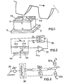
- a differential sensor is shown in principle in FIG. It consists of a gear-like rotor 1 and a stator which contains a permanent magnet 2, a substrate 3 (ferrite) with field plate resistors 4a and 4b applied thereon and a soft magnetic yoke part 5.
- a gear-like rotor 1 and a stator which contains a permanent magnet 2, a substrate 3 (ferrite) with field plate resistors 4a and 4b applied thereon and a soft magnetic yoke part 5.
- the rotor is turned, the flux of the magnetic field of the permanent magnet 2 is changed.
- the field plate resistors are thereby varied in their resistance value.
- FIG. 2 shows the electrical connection of the two resistors 4a and 4b.
- the adjacent terminals of the resistors 4a and 4b are connected to each other and connected to earth.
- the other two terminals of the resistors 4a and 4b are connected to a Doppler current source 20 which supplies the two resistors a current dependent only on the temperature but otherwise constant 1 0th
- the desired output voltage U A the frequency of which is proportional to the speed of the rotor, can also be tapped between the two supply lines.
- Parallel to the resistors 4a and 4b is a high-resistance voltage divider made up of the same resistors 21a and 21b.
- a voltage U A * is tapped between the connections of the two pairs of resistors 4a / 4b and 21a / 21b, which is compared in a comparator 22 with a constant voltage U o .
- the deviation of the voltage UA from the voltage U o (U o is the maximum permissible mean supply voltage of the field plates at which there is no thermal overload of the field plates in the operating range) is fed to the dual current source 20 for regulating the current 1 0 .
- This regulation is necessary to compensate for the influence of changes in the resistors 4a and 4b caused by temperature fluctuations.
- the regulation is carried out in such a way that the voltage U o is at the rest resistance of each field plate at all temperatures. If the resistance value falls, the current is increased accordingly.
- the output voltage is with this solution if R is the rest resistance of the field plates and ⁇ R is their difference when the rotor is rotating.
- the sensor 30 is connected to the current sources 32a and 32b via supply lines 31.
- Interference voltage sources Us and Ust 2 are shown in the supply lines 31 and the ground lines. Interference voltages from these sources are eliminated in the present circuit as common mode signals.
Landscapes
- Physics & Mathematics (AREA)
- General Physics & Mathematics (AREA)
- Condensed Matter Physics & Semiconductors (AREA)
- Transmission And Conversion Of Sensor Element Output (AREA)
- Measuring Magnetic Variables (AREA)
Claims (2)
Applications Claiming Priority (2)
| Application Number | Priority Date | Filing Date | Title |
|---|---|---|---|
| DE19843435867 DE3435867A1 (de) | 1984-09-29 | 1984-09-29 | Differentialsensor |
| DE3435867 | 1984-09-29 |
Publications (2)
| Publication Number | Publication Date |
|---|---|
| EP0181467A1 EP0181467A1 (fr) | 1986-05-21 |
| EP0181467B1 true EP0181467B1 (fr) | 1990-07-18 |
Family
ID=6246734
Family Applications (1)
| Application Number | Title | Priority Date | Filing Date |
|---|---|---|---|
| EP85111918A Expired - Lifetime EP0181467B1 (fr) | 1984-09-29 | 1985-09-20 | Capteur différentiel |
Country Status (4)
| Country | Link |
|---|---|
| US (1) | US4727323A (fr) |
| EP (1) | EP0181467B1 (fr) |
| JP (1) | JPH0621799B2 (fr) |
| DE (2) | DE3435867A1 (fr) |
Families Citing this family (37)
| Publication number | Priority date | Publication date | Assignee | Title |
|---|---|---|---|---|
| DE3513148A1 (de) * | 1985-04-12 | 1986-10-23 | Robert Bosch Gmbh, 7000 Stuttgart | Integrierter drehzahlsensor mit magnetfeldabhaengigen sensorwiderstaenden |
| DE3639340A1 (de) * | 1986-11-18 | 1988-05-26 | Mueller Arnold Gmbh Co Kg | Einrichtung zur erfassung und uebertragung einer messgroesse |
| DE3705403A1 (de) * | 1987-02-20 | 1988-09-01 | Standard Elektrik Lorenz Ag | Schaltung zur verstaerkung und formung eines wechselspannungssignals |
| JP2556851B2 (ja) * | 1987-03-02 | 1996-11-27 | 三菱化学株式会社 | 磁気抵抗素子 |
| US4859941A (en) * | 1987-03-18 | 1989-08-22 | Sprague Electric Company | Proximity selectro with integral magnet, pole-piece plate and pair of magnetic transducers |
| US4922197A (en) * | 1988-08-01 | 1990-05-01 | Eaton Corporation | High resolution proximity detector employing magnetoresistive sensor disposed within a pressure resistant enclosure |
| US4879610A (en) * | 1988-09-28 | 1989-11-07 | International Business Machines Corporation | Protective circuit for a magnetoresistive element |
| JPH02141617A (ja) * | 1988-11-24 | 1990-05-31 | Japan Servo Co Ltd | 磁気エンコーダ |
| EP0427882B1 (fr) * | 1989-11-14 | 1995-03-08 | Robert Bosch Gmbh | Dispositif de mesure des déplacements faibles |
| US5041784A (en) * | 1989-11-16 | 1991-08-20 | Visi-Trak Corporation | Magnetic sensor with rectangular field distorting flux bar |
| DE4012480A1 (de) * | 1990-04-19 | 1991-10-24 | Teves Gmbh Alfred | Messwertaufnehmer fuer eine elektromotorisch angetriebene servolenkung |
| US5103353A (en) * | 1990-05-01 | 1992-04-07 | International Business Machines Corporation | Low noise amplifier with short circuit protection for signals from magnetoresistive element |
| US5589768A (en) * | 1990-07-30 | 1996-12-31 | Mitsubishi Steel Mfg. Co., Ltd. | Magnetoresistance-effect magnetic sensor of the temperature compensating type |
| US5065094A (en) * | 1990-08-07 | 1991-11-12 | Seagate Technology, Inc. | Two terminal magnetoresistive sensor having DC blocking capacitor |
| DE4123128A1 (de) * | 1991-07-12 | 1993-01-14 | Bosch Gmbh Robert | Wirbelstrom-drehzahlsensor |
| DE9110524U1 (de) * | 1991-08-26 | 1992-09-24 | Siemens AG, 8000 München | Vorrichtung zur Winkellagebestimmung einer Lastwelle mit einem Meß- und einem Nachlaufzahnrad |
| DE4129576C2 (de) * | 1991-09-06 | 2001-05-31 | Mueller Arnold Gmbh Co Kg | Magnetisches Meßsystem zur Drehwinkelmessung |
| DE4129577C2 (de) * | 1991-09-06 | 1999-11-25 | Mueller Arnold Gmbh Co Kg | Meßsystem zur Drehwinkelmessung |
| US5402064A (en) * | 1992-09-02 | 1995-03-28 | Santa Barbara Research Center | Magnetoresistive sensor circuit with high output voltage swing and temperature compensation |
| US5404102A (en) * | 1993-01-06 | 1995-04-04 | General Motors Corporation | Method and apparatus for electrically exciting a magneto-resistor device |
| DE4319322C2 (de) * | 1993-06-11 | 1998-04-23 | Heidenhain Gmbh Dr Johannes | Positionsmeßeinrichtung |
| DE19520683A1 (de) * | 1995-06-07 | 1996-12-12 | Teves Gmbh Alfred | Anordnung zur Erfassung einer Bewegung |
| US5767668A (en) * | 1996-01-18 | 1998-06-16 | Case Western Reserve University | Remote current sensor |
| DE19628566A1 (de) * | 1996-07-16 | 1998-01-29 | Bosch Gmbh Robert | Magnetfeldempfindlicher Sensor |
| EP0855599A3 (fr) * | 1997-01-24 | 2001-05-02 | Siemens Aktiengesellschaft | Compas électronique |
| US6268721B1 (en) * | 1999-02-17 | 2001-07-31 | Delphi Technologies, Inc. | Low cost binary encoded crankshaft position sensor |
| US7244450B2 (en) * | 1999-04-01 | 2007-07-17 | Inex Pharmaceuticals Corporation | Compositions and methods for treating lymphoma |
| US6714000B2 (en) * | 1999-06-14 | 2004-03-30 | Genscape, Inc. | Method for monitoring power and current flow |
| US6291989B1 (en) * | 1999-08-12 | 2001-09-18 | Delphi Technologies, Inc. | Differential magnetic position sensor with adaptive matching for detecting angular position of a toothed target wheel |
| US20010040446A1 (en) | 2000-04-13 | 2001-11-15 | Sterling Lapinksi | Apparatus and method for the measurement and monitoring of electrical power generation and transmission |
| JP2005516897A (ja) * | 2001-11-07 | 2005-06-09 | イネックス ファーマシューティカルズ コーポレイション | 改善された粘膜のワクチン及びその使用方法 |
| US7015557B2 (en) * | 2004-04-16 | 2006-03-21 | Honeywell International Inc. | Hall element with segmented field plate |
| DE102004027386A1 (de) | 2004-06-04 | 2006-01-05 | Vse Volumentechnik Gmbh | Durchflussmengenfühler |
| WO2007132389A1 (fr) * | 2006-05-12 | 2007-11-22 | Nxp B.V. | Interface de courant comportant un condensateur de blocage fixé à une broche supplémentaire |
| US7805992B2 (en) * | 2007-03-27 | 2010-10-05 | Honeywell International Inc. | Gas sensor housing for use in high temperature gas environments |
| US7825656B2 (en) * | 2007-05-30 | 2010-11-02 | Infineon Technologies Ag | Temperature compensation for spaced apart sensors |
| DE102018210595A1 (de) * | 2018-06-28 | 2020-01-02 | Infineon Technologies Ag | Sensorvorrichtungen und Verfahren zur Herstellung von Sensorvorrichtungen |
Family Cites Families (9)
| Publication number | Priority date | Publication date | Assignee | Title |
|---|---|---|---|---|
| CH421288A (de) * | 1963-10-26 | 1966-09-30 | Siemens Ag | Einrichtung zur Messung der räumlichen Ableitung von Magnetfeldern |
| US3286161A (en) * | 1963-12-04 | 1966-11-15 | Ronald H Jones | Magneto-resistive potentiometer |
| US3835377A (en) * | 1970-03-09 | 1974-09-10 | Kogyo Gijutsuin | Three terminal magnetoresistive magnetic field detector in which voltages of opposite polarity relative to ground are applied to opposite ends |
| JPS5337204A (en) * | 1976-06-11 | 1978-04-06 | Babcock & Wilcox Ltd | Boiler for use in ship |
| US4296377A (en) * | 1978-03-27 | 1981-10-20 | Sony Corporation | Magnetic signal field sensor that is substantially immune to angular displacement relative to the signal field |
| JPS5826215A (ja) * | 1981-08-07 | 1983-02-16 | Nippon Denso Co Ltd | 回転角検出装置 |
| US4616281A (en) * | 1982-03-10 | 1986-10-07 | Copal Company Limited | Displacement detecting apparatus comprising magnetoresistive elements |
| JPS59114412A (ja) * | 1982-12-21 | 1984-07-02 | Copal Co Ltd | 磁気抵抗素子を具える磁気検出器 |
| US4476454A (en) * | 1983-06-30 | 1984-10-09 | International Business Machines Corporation | New magnetoresistive materials |
-
1984
- 1984-09-29 DE DE19843435867 patent/DE3435867A1/de not_active Withdrawn
-
1985
- 1985-09-20 EP EP85111918A patent/EP0181467B1/fr not_active Expired - Lifetime
- 1985-09-20 DE DE8585111918T patent/DE3578734D1/de not_active Expired - Lifetime
- 1985-09-27 JP JP60212771A patent/JPH0621799B2/ja not_active Expired - Lifetime
- 1985-09-30 US US06/781,957 patent/US4727323A/en not_active Expired - Fee Related
Also Published As
| Publication number | Publication date |
|---|---|
| EP0181467A1 (fr) | 1986-05-21 |
| DE3578734D1 (en) | 1990-08-23 |
| DE3435867A1 (de) | 1986-04-10 |
| US4727323A (en) | 1988-02-23 |
| JPS6186614A (ja) | 1986-05-02 |
| JPH0621799B2 (ja) | 1994-03-23 |
Similar Documents
| Publication | Publication Date | Title |
|---|---|---|
| EP0181467B1 (fr) | Capteur différentiel | |
| DE2937866C3 (de) | Kollektorloser Gleichstrommotor | |
| DE69719668T2 (de) | Magnetische Kodiereinrichtung | |
| DE3308352A1 (de) | Magnetdetektorvorrichtung | |
| CH651671A5 (de) | Anordnung zur messung elektrischer leistung oder energie. | |
| EP0654145A1 (fr) | Capteur de champs magnetiques constitue d'un conducteur d'inversion magnetique et d'une ou plusieurs resistances magnetoresistives | |
| EP0954085A1 (fr) | Capteur vertical à effet Hall et moteur électrique sans balai avec un capteur vertical à effet Hall | |
| EP0640190B1 (fr) | Regulateur de palier magnetique | |
| EP0129817B1 (fr) | Circuit avec générateur à effet Hall | |
| DE10159607B4 (de) | Analog/Digital-Signalwandlereinrichtung mit galvanischer Trennung in ihrem Singalübertragungsweg | |
| DE2749763C2 (fr) | ||
| DE3102998C2 (de) | Anordnung zur Messung elektrischer Leistung mit einem Multiplizierer | |
| DE2743661A1 (de) | Gleichstrommotor mit mehrphasiger staenderwicklung und durch winkelstellungsgeber gesteuerter elektronischer kommutierungseinrichtung | |
| EP0686850A1 (fr) | Circuit de mesure de courants continus avec isolation de tension entre le circuit de courant et le circuit de mesure | |
| DE2547764C3 (de) | Elektronisch kommutierter Gleichstrommotor | |
| DE2712795A1 (de) | Synchronuebertragungsgeraet der vernier- resolver-bauart | |
| DE102009029528A1 (de) | Integrierter Schaltkreis zur Informationsübertragung | |
| DE1690076B1 (de) | Verfahren zur verminderung des umkehreffektes von hallgene ratoren | |
| DE584850C (de) | Einrichtung zur Ermittlung oder zum Ausgleich des Stellungsunterschiedes zweier raeumlich getrennter Wellen | |
| DE2035027B2 (de) | Drehmoment-Gleichstrommotor | |
| AT383707B (de) | Drehzahlgeber | |
| DE3390546T1 (de) | Drehzahlgeber | |
| DE527676C (de) | Vorrichtung zur Messung elektrischer Groessen und ihrer Summen am fernen Ort mit Hilfe von Wechselstrom | |
| DE3933707B4 (de) | Schaltung zum Kompensieren zeitlicher Instabilitäten der Multiplikationsschaltung mit Hall-Sensoren in einem Wattmeter oder Elektrizitätszähler | |
| DE3639340C2 (fr) |
Legal Events
| Date | Code | Title | Description |
|---|---|---|---|
| PUAI | Public reference made under article 153(3) epc to a published international application that has entered the european phase |
Free format text: ORIGINAL CODE: 0009012 |
|
| AK | Designated contracting states |
Kind code of ref document: A1 Designated state(s): DE FR GB IT |
|
| 17P | Request for examination filed |
Effective date: 19860611 |
|
| 17Q | First examination report despatched |
Effective date: 19881215 |
|
| GRAA | (expected) grant |
Free format text: ORIGINAL CODE: 0009210 |
|
| AK | Designated contracting states |
Kind code of ref document: B1 Designated state(s): DE FR GB IT |
|
| GBT | Gb: translation of ep patent filed (gb section 77(6)(a)/1977) | ||
| REF | Corresponds to: |
Ref document number: 3578734 Country of ref document: DE Date of ref document: 19900823 |
|
| ET | Fr: translation filed | ||
| ITF | It: translation for a ep patent filed | ||
| PLBE | No opposition filed within time limit |
Free format text: ORIGINAL CODE: 0009261 |
|
| STAA | Information on the status of an ep patent application or granted ep patent |
Free format text: STATUS: NO OPPOSITION FILED WITHIN TIME LIMIT |
|
| 26N | No opposition filed | ||
| ITTA | It: last paid annual fee | ||
| PGFP | Annual fee paid to national office [announced via postgrant information from national office to epo] |
Ref country code: GB Payment date: 19940912 Year of fee payment: 10 |
|
| PGFP | Annual fee paid to national office [announced via postgrant information from national office to epo] |
Ref country code: FR Payment date: 19940930 Year of fee payment: 10 |
|
| REG | Reference to a national code |
Ref country code: GB Ref legal event code: 746 Effective date: 19940921 |
|
| PGFP | Annual fee paid to national office [announced via postgrant information from national office to epo] |
Ref country code: DE Payment date: 19941201 Year of fee payment: 10 |
|
| REG | Reference to a national code |
Ref country code: FR Ref legal event code: DL |
|
| ITPR | It: changes in ownership of a european patent |
Owner name: OFFERTA DI LICENZA AL PUBBLICO |
|
| PG25 | Lapsed in a contracting state [announced via postgrant information from national office to epo] |
Ref country code: GB Effective date: 19950920 |
|
| GBPC | Gb: european patent ceased through non-payment of renewal fee |
Effective date: 19950920 |
|
| PG25 | Lapsed in a contracting state [announced via postgrant information from national office to epo] |
Ref country code: FR Effective date: 19960531 |
|
| PG25 | Lapsed in a contracting state [announced via postgrant information from national office to epo] |
Ref country code: DE Effective date: 19960601 |
|
| REG | Reference to a national code |
Ref country code: FR Ref legal event code: ST |