EP0181479A1 - Kraftstoff-Einspritzdüse für Brennkraftmaschinen - Google Patents
Kraftstoff-Einspritzdüse für Brennkraftmaschinen Download PDFInfo
- Publication number
- EP0181479A1 EP0181479A1 EP85112504A EP85112504A EP0181479A1 EP 0181479 A1 EP0181479 A1 EP 0181479A1 EP 85112504 A EP85112504 A EP 85112504A EP 85112504 A EP85112504 A EP 85112504A EP 0181479 A1 EP0181479 A1 EP 0181479A1
- Authority
- EP
- European Patent Office
- Prior art keywords
- valve needle
- spring
- injection nozzle
- compression spring
- spring element
- Prior art date
- Legal status (The legal status is an assumption and is not a legal conclusion. Google has not performed a legal analysis and makes no representation as to the accuracy of the status listed.)
- Granted
Links
- 238000002347 injection Methods 0.000 title claims abstract description 12
- 239000007924 injection Substances 0.000 title claims abstract description 12
- 239000000446 fuel Substances 0.000 title claims abstract description 7
- 238000002485 combustion reaction Methods 0.000 title claims abstract 3
- 230000006835 compression Effects 0.000 claims abstract description 12
- 238000007906 compression Methods 0.000 claims abstract description 12
- 230000000284 resting effect Effects 0.000 claims 2
- 238000013016 damping Methods 0.000 claims 1
- 238000007789 sealing Methods 0.000 description 2
- 230000002411 adverse Effects 0.000 description 1
- 239000007921 spray Substances 0.000 description 1
Images
Classifications
-
- F—MECHANICAL ENGINEERING; LIGHTING; HEATING; WEAPONS; BLASTING
- F02—COMBUSTION ENGINES; HOT-GAS OR COMBUSTION-PRODUCT ENGINE PLANTS
- F02M—SUPPLYING COMBUSTION ENGINES IN GENERAL WITH COMBUSTIBLE MIXTURES OR CONSTITUENTS THEREOF
- F02M61/00—Fuel-injectors not provided for in groups F02M39/00 - F02M57/00 or F02M67/00
- F02M61/16—Details not provided for in, or of interest apart from, the apparatus of groups F02M61/02 - F02M61/14
- F02M61/20—Closing valves mechanically, e.g. arrangements of springs or weights or permanent magnets; Damping of valve lift
Definitions
- the invention relates to a fuel injection nozzle according to the preamble of the main claim.
- the compression spring element is formed by a single coil spring, the spring ends of which twist somewhat against each other when the spring is compressed. The rotational movements cause wear on the end faces of the spring and on the adjacent components, which in unfavorable cases can adversely affect the quality of the injection.
- the arrangement according to the invention with the characterizing features of the main claim has the opposite partly that with appropriate coordination of the two coil springs, a relative rotary movement between the two outer ends of the compression spring element can be completely avoided.
- the still existing rotary movements of the ends of the two individual coil springs are shifted to their connection point, where the rotary movements take place in the same direction and wear cannot occur.
- the mutually facing ends of the two individual coil springs can advantageously be attached to an intermediate piece, which can also be guided on the wall of the spring chamber.
- the proposal according to the invention can be implemented with the same advantage both with injection nozzles with an inwardly opening valve needle and with injection nozzles with an outwardly opening valve needle.
- the injection nozzle shown has a nozzle holder 10, an intermediate plate 11 and a nozzle body 12, which is clamped together with the intermediate plate 11 by a union nut 13 on the nozzle holder 10.
- a guide bore 14 for receiving a valve needle 15 and a valve seat 16 are formed, which cooperates with a sealing cone 17 on the valve needle 15.
- a needle shaft 18 Connected to the sealing cone 17 is a needle shaft 18, which is larger in diameter and slides in the guide bore 14, and a pressure pin 19.
- the annular shoulder formed on the valve needle 15 between the needle shaft 18 and the pressure pin 19 is removed from the intermediate plate 11 by an amount corresponding to the total stroke of the valve needle when the valve needle 15 is seated on the valve seat 16.
- a spring chamber 21 which is open at the end is formed in the nozzle holder 10 and merges into a blind bore 23 on a shoulder 22.
- a compression spring element 25 which is described in more detail below, is supported at one end via a disk 26 on the shoulder 22 and at the other end on the pressure piece 20.
- the fuel passes through inlet channels 29 to 32 and ring channels 33, 34 into a pressure chamber 35 of the nozzle body 12, which has a connection to a spray opening 36 via the valve seat 16.
- a connection bore 38 for a leak oil line opens obliquely into the bag opening 23.
- the compression spring element 25 consists of two oppositely wound coil springs 40 and 41, the mutually facing ends of which are fastened to an annular intermediate piece 42. This is loosely guided on the wall of the spring chamber 21 with ample play and provided with a central bore 43 for the unhindered passage of leak oil.
- the two coil springs 40 and 41 are matched to one another so that when the compression spring element 25 is compressed, there is no relative rotation of its two outer spring ends and therefore no relative rotation of these spring ends with respect to the disk 26 and the pressure piece 20.
- the relative rotations of the spring ends of each individual coil spring 40, 41 are transmitted in the same direction to the intermediate piece 42 and are smoothly received by the latter. This avoids any wear on the outer spring ends of the compression spring element 25, on the disk 26 and on the pressure piece 20.
Landscapes
- Engineering & Computer Science (AREA)
- Chemical & Material Sciences (AREA)
- Combustion & Propulsion (AREA)
- Mechanical Engineering (AREA)
- General Engineering & Computer Science (AREA)
- Fuel-Injection Apparatus (AREA)
Abstract
Description
- Die Erfindung geht aus von einer Kraftstoff-Einspritzdüse nach der Gattung des Hauptanspruchs. Bei den bekannten Einspritzdüsen dieser Gattung ist das Druckfederelement durch eine einzige Schraubenfeder gebildet, deren Federenden sich beim Zusammendrücken der Feder etwas gegeneinander verdrehen. Durch die Drehbewegungen wird an den Stirnseiten der Feder und an den anliegenden Bauteilen ein Verschleiß verursacht, der in ungünstigen Fällen die Einspritzgüte nachteilig beeinflußen kann.
- Die erfindungsgemäße Anordnung mit den kennzeichnenden Merkmalen des Hauptanspruchs hat demgegenüber den Vorteil, daß bei entsprechender Abstimmung der beiden Schraubenfedern eine relative Drehbewegung zwischen den beiden äußeren Enden des Druckfederelementes vollständig vermieden werden kann. Die nach wie vor vorhandenen Drehbewegungen der Enden der beiden einzelnen Schraubenfedern werden in ihre Verbindungsstelle verlagert, wo die Drehbewegungen gleichsinnig erfolgen und Verschleiß nicht auftreten kann. Die einander zugekehrten Enden der beiden einzelnen Schraubenfedern können vorteilhaft an einem Zwischenstück befestigt sein, welches auch an der Wand der Federkammer geführt sein kann.
- Der erfindungsgemäße Vorschlag kann mit gleichem Vorteil sowohl bei Einspritzdüsen mit nach innen öffnender Ventilnadel als auch bei Einspritzdüsen mit nach außen öffnender Ventilnadel verwirklicht werden.
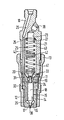
- Ein Ausführungsbeispiel der Erfindung ist in der Zeichnung dargestellt und in der nachfolgenden Beschreibung näher erläutert. Die einzige Figur zeigt einen Längsschnitt durch das Ausführungsbeispiel.
- Die dargestellte Einspritzdüse hat einen Düsenhalter 10, eine Zwischenplatte 11 und einen Düsenkörper 12, welcher gemeinsam mit der Zwischenplatte 11 durch eine Überwurfmutter 13 am Düsenhalter 10 festgespannt ist.
- Im Düsenkörper 12 sind eine Führungsbohrung 14 zur Aufnahme einer Ventilnadel 15 und ein Ventilsitz 16 gebildet, der mit einem Dichtkegel 17 an der Ventilnadel 15 zusammenwirkt. An den Dichtkegel 17 schließt sich ein im Durchmesser größerer, in der Führungsbohrung 14 gleitender Nadelschaft 18 und ein Druckzapfen 19 an. Auf dem Druckzapfen 19 sitzt ein Druckstück 20, welches mit einem nach unten weisenden Ringkragen den Druckzapfen 19 mit dem erforderlichen Bewegungsspiel umgreift. Die zwischen Nadelschaft 18 und Druckzapfen 19 gebildete Ringschulter an der Ventilnadel 15 ist bei auf dem Ventilsitz 16 aufsitzender Ventilnadel 15 um ein den Gesamthub der Ventilnadel entsprechendes Maß von der Zwischenplatte 11 entfernt.
- Im Düsenhalter 10 ist eine stirnseitig offene Federkammer 21 gebildet, welche an einer Schulter 22 in eine Sackbohrung 23 übergeht. Ein nachstehend im einzelnen näher beschriebenes Druckfederelement 25 stützt sich an einem Ende über eine Scheibe 26 an der Schulter 22 und am anderen Ende am Druckstück 20 ab. Der Kraftstoff gelangt über Zulaufkanäle 29 bis 32 und Ringkanäle 33, 34 in einen Druckraum 35 des Düsenkörpers 12, der über den Ventilsitz 16 Verbindung mit einer Spritzöffnung 36 hat. In die Sackbchrung 23 mündet schräg eine Anschlußbohrung 38 für eine Leckölleitung ein.
- Das Druckfederelement 25 besteht aus zwei gegensinnig gewickelten Schraubenfedern 40 und 41, deren einander zugekehrte Enden an einem ringförmigen Zwischenstück 42 befestigt sind. Dieses ist an der Wand der Federkammer 21 mit reichlich bemessenem Spiel lose geführt und mit einer zentralen Bohrung 43 zum ungehinderten Durchtritt von Lecköl versehen. Die beiden Schraubenfedern 40 und 41 sind so aufeinander abgestimmt, daß beim Zusammendrücken des Druckfederelementes 25 keine Relativdrehung seiner beiden äußeren Federenden und daher auch keine Relativdrehung dieser Federenden gegenüber der Scheibe 26 und dem Druckstück 20 auftreten. Die Relativdrehungen der Federenden jeder einzelnen Schraubenfeder 40, 41 werden gleichsinnig auf das Zwischenstück 42 übertragen und von diesem reibungslos aufgenommen. Dadurch wird jeder Verschleiß an den äußeren Federenden des Druckfederelementes 25, an der Scheibe 26 und an dem Druckstück 20 vermieden.
- In manchen Fällen kann es auch zweckmäßig sein, das Zwischenstück 42 mit engem Spiel an der Wand der Federkammer 21 zu führen, so daß sich eine Dämpfung der Federbewegung ergibt.
Claims (4)
Applications Claiming Priority (2)
| Application Number | Priority Date | Filing Date | Title |
|---|---|---|---|
| DE19843440396 DE3440396A1 (de) | 1984-11-06 | 1984-11-06 | Kraftstoff-einspritzduese fuer brennkraftmaschinen |
| DE3440396 | 1984-11-06 |
Publications (2)
| Publication Number | Publication Date |
|---|---|
| EP0181479A1 true EP0181479A1 (de) | 1986-05-21 |
| EP0181479B1 EP0181479B1 (de) | 1989-04-26 |
Family
ID=6249542
Family Applications (1)
| Application Number | Title | Priority Date | Filing Date |
|---|---|---|---|
| EP85112504A Expired EP0181479B1 (de) | 1984-11-06 | 1985-10-03 | Kraftstoff-Einspritzdüse für Brennkraftmaschinen |
Country Status (3)
| Country | Link |
|---|---|
| EP (1) | EP0181479B1 (de) |
| JP (1) | JPS61116064A (de) |
| DE (2) | DE3440396A1 (de) |
Cited By (1)
| Publication number | Priority date | Publication date | Assignee | Title |
|---|---|---|---|---|
| US8939128B2 (en) | 2010-05-07 | 2015-01-27 | Liebherr Machines Bulle Sa | High-pressure injector |
Families Citing this family (2)
| Publication number | Priority date | Publication date | Assignee | Title |
|---|---|---|---|---|
| DE10048597A1 (de) * | 2000-09-30 | 2002-04-11 | Bosch Gmbh Robert | Kraftstoffeinspritzventil für Brennkraftmaschinen |
| JP7058505B2 (ja) * | 2018-01-09 | 2022-04-22 | ロベルト・ボッシュ・ゲゼルシャフト・ミト・ベシュレンクテル・ハフツング | 燃料供給ポンプ |
Citations (2)
| Publication number | Priority date | Publication date | Assignee | Title |
|---|---|---|---|---|
| CH329505A (de) * | 1955-02-23 | 1958-04-30 | Saurer Ag Adolph | Verfahren zum Steuern des Durchflussquerschnittes von Einspritzdüsen für Brennkraftmaschinen und Einspritzdüse zur Durchführung des Verfahrens |
| GB2023228A (en) * | 1978-06-14 | 1979-12-28 | Bosch Gmbh Robert | Fuel injection nozzle for an internal combustion engine |
-
1984
- 1984-11-06 DE DE19843440396 patent/DE3440396A1/de not_active Withdrawn
-
1985
- 1985-09-30 JP JP60215257A patent/JPS61116064A/ja active Pending
- 1985-10-03 EP EP85112504A patent/EP0181479B1/de not_active Expired
- 1985-10-03 DE DE8585112504T patent/DE3569785D1/de not_active Expired
Patent Citations (2)
| Publication number | Priority date | Publication date | Assignee | Title |
|---|---|---|---|---|
| CH329505A (de) * | 1955-02-23 | 1958-04-30 | Saurer Ag Adolph | Verfahren zum Steuern des Durchflussquerschnittes von Einspritzdüsen für Brennkraftmaschinen und Einspritzdüse zur Durchführung des Verfahrens |
| GB2023228A (en) * | 1978-06-14 | 1979-12-28 | Bosch Gmbh Robert | Fuel injection nozzle for an internal combustion engine |
Cited By (1)
| Publication number | Priority date | Publication date | Assignee | Title |
|---|---|---|---|---|
| US8939128B2 (en) | 2010-05-07 | 2015-01-27 | Liebherr Machines Bulle Sa | High-pressure injector |
Also Published As
| Publication number | Publication date |
|---|---|
| JPS61116064A (ja) | 1986-06-03 |
| DE3440396A1 (de) | 1986-05-07 |
| DE3569785D1 (en) | 1989-06-01 |
| EP0181479B1 (de) | 1989-04-26 |
Similar Documents
| Publication | Publication Date | Title |
|---|---|---|
| DE69505763T2 (de) | Ansaugrohr mit Schwenkklappen für eine Brennkraftmaschine | |
| DE2336575B2 (de) | Elektromagnetisch gesteuerte kraftstoffeinspritzduese fuer kolbenbrennkraftmaschinen | |
| DE4131537A1 (de) | Brennstoffverteiler | |
| DE4237469B4 (de) | Kraftstoffeinspritzeinrichtung, insbesondere Pumpedüse für Brennkraftmaschinen | |
| DE68905502T2 (de) | Brennstoffeinspritzventil. | |
| DE3107826A1 (de) | Von dem verdichtungsdruck betaetigte kraftstoffeinspritzeinrichtung fuer brennkraftmaschinen | |
| WO1998016736A1 (de) | Kraftstoffeinspritzventil für brennkraftmaschinen | |
| DE3302220C2 (de) | Kraftstoffeinspritzdüse für eine luftverdichtende, selbstzündende Hubkolben-Brennkraftmaschine | |
| EP0516628B1 (de) | Kraftstoff-einspritzdüse für brennkraftmaschinen | |
| EP0298254B1 (de) | Kraftstoffeinspritzpumpe | |
| DE4230641A1 (de) | Kraftstoff-Einspritzdüse mit Additiveinspritzung für Dieselmotoren | |
| EP0181479B1 (de) | Kraftstoff-Einspritzdüse für Brennkraftmaschinen | |
| DE3421074A1 (de) | Kraftstoffeinspritzduese | |
| DE3019167C2 (de) | ||
| EP0030258B1 (de) | Kraftstoffeinspritzdüse für Brennkraftmaschinen | |
| EP0890735A2 (de) | Kraftstoffeinspritzventil | |
| DE3230671A1 (de) | Einspritzventil | |
| EP1144848B1 (de) | Brennstoffeinspritzventil | |
| DE4140070C2 (de) | Kraftstoffeinspritzventil für Brennkraftmaschinen | |
| EP0698182A1 (de) | Einspritzdüse für brennkraftmaschinen | |
| DE3740283A1 (de) | Einspritzventil | |
| EP0197057A1 (de) | Kraftstoff-einspritzdüse für brennkraftmaschinen | |
| AT395638B (de) | Einspritzduese fuer brennkraftmaschinen, insbesondere dieselmotoren | |
| DE3325451A1 (de) | Kraftstoffeinlassventil fuer brennkraftmaschinen | |
| DE2120465A1 (de) | Einspritzventil, insbesondere für ventilgesteuerte Brennkraftmaschinen |
Legal Events
| Date | Code | Title | Description |
|---|---|---|---|
| PUAI | Public reference made under article 153(3) epc to a published international application that has entered the european phase |
Free format text: ORIGINAL CODE: 0009012 |
|
| AK | Designated contracting states |
Kind code of ref document: A1 Designated state(s): DE FR GB IT |
|
| 17P | Request for examination filed |
Effective date: 19861120 |
|
| 17Q | First examination report despatched |
Effective date: 19870416 |
|
| GRAA | (expected) grant |
Free format text: ORIGINAL CODE: 0009210 |
|
| AK | Designated contracting states |
Kind code of ref document: B1 Designated state(s): DE FR GB IT |
|
| GBT | Gb: translation of ep patent filed (gb section 77(6)(a)/1977) | ||
| REF | Corresponds to: |
Ref document number: 3569785 Country of ref document: DE Date of ref document: 19890601 |
|
| ET | Fr: translation filed | ||
| ITF | It: translation for a ep patent filed | ||
| PLBE | No opposition filed within time limit |
Free format text: ORIGINAL CODE: 0009261 |
|
| STAA | Information on the status of an ep patent application or granted ep patent |
Free format text: STATUS: NO OPPOSITION FILED WITHIN TIME LIMIT |
|
| 26N | No opposition filed | ||
| PGFP | Annual fee paid to national office [announced via postgrant information from national office to epo] |
Ref country code: GB Payment date: 19900905 Year of fee payment: 6 |
|
| PGFP | Annual fee paid to national office [announced via postgrant information from national office to epo] |
Ref country code: FR Payment date: 19901030 Year of fee payment: 6 |
|
| ITTA | It: last paid annual fee | ||
| PGFP | Annual fee paid to national office [announced via postgrant information from national office to epo] |
Ref country code: DE Payment date: 19901227 Year of fee payment: 6 |
|
| PG25 | Lapsed in a contracting state [announced via postgrant information from national office to epo] |
Ref country code: GB Effective date: 19911003 |
|
| GBPC | Gb: european patent ceased through non-payment of renewal fee | ||
| PG25 | Lapsed in a contracting state [announced via postgrant information from national office to epo] |
Ref country code: FR Effective date: 19920630 |
|
| PG25 | Lapsed in a contracting state [announced via postgrant information from national office to epo] |
Ref country code: DE Effective date: 19920701 |
|
| REG | Reference to a national code |
Ref country code: FR Ref legal event code: ST |