EP0181725A1 - Dispositif de charge à effet corona - Google Patents
Dispositif de charge à effet corona Download PDFInfo
- Publication number
- EP0181725A1 EP0181725A1 EP85307766A EP85307766A EP0181725A1 EP 0181725 A1 EP0181725 A1 EP 0181725A1 EP 85307766 A EP85307766 A EP 85307766A EP 85307766 A EP85307766 A EP 85307766A EP 0181725 A1 EP0181725 A1 EP 0181725A1
- Authority
- EP
- European Patent Office
- Prior art keywords
- corona
- wires
- wire
- charging
- coronode
- Prior art date
- Legal status (The legal status is an assumption and is not a legal conclusion. Google has not performed a legal analysis and makes no representation as to the accuracy of the status listed.)
- Granted
Links
- 150000002500 ions Chemical class 0.000 claims description 4
- 229910001925 ruthenium oxide Inorganic materials 0.000 claims description 2
- WOCIAKWEIIZHES-UHFFFAOYSA-N ruthenium(iv) oxide Chemical compound O=[Ru]=O WOCIAKWEIIZHES-UHFFFAOYSA-N 0.000 claims description 2
- 238000007665 sagging Methods 0.000 abstract description 8
- 108091008695 photoreceptors Proteins 0.000 description 9
- 239000002245 particle Substances 0.000 description 8
- 238000012546 transfer Methods 0.000 description 5
- 239000000203 mixture Substances 0.000 description 4
- 238000004140 cleaning Methods 0.000 description 3
- 238000011161 development Methods 0.000 description 3
- 239000011521 glass Substances 0.000 description 3
- 239000008187 granular material Substances 0.000 description 3
- 238000000034 method Methods 0.000 description 3
- 239000000843 powder Substances 0.000 description 3
- 238000012545 processing Methods 0.000 description 3
- 239000000758 substrate Substances 0.000 description 3
- BUGBHKTXTAQXES-UHFFFAOYSA-N Selenium Chemical compound [Se] BUGBHKTXTAQXES-UHFFFAOYSA-N 0.000 description 2
- XAGFODPZIPBFFR-UHFFFAOYSA-N aluminium Chemical compound [Al] XAGFODPZIPBFFR-UHFFFAOYSA-N 0.000 description 2
- 229910052782 aluminium Inorganic materials 0.000 description 2
- 239000011230 binding agent Substances 0.000 description 2
- 238000007599 discharging Methods 0.000 description 2
- 239000000463 material Substances 0.000 description 2
- 230000004048 modification Effects 0.000 description 2
- 238000012986 modification Methods 0.000 description 2
- 230000008569 process Effects 0.000 description 2
- 108020003175 receptors Proteins 0.000 description 2
- 229910052711 selenium Inorganic materials 0.000 description 2
- 239000011669 selenium Substances 0.000 description 2
- 229920002799 BoPET Polymers 0.000 description 1
- 238000006424 Flood reaction Methods 0.000 description 1
- 239000005041 Mylar™ Substances 0.000 description 1
- CBENFWSGALASAD-UHFFFAOYSA-N Ozone Chemical compound [O-][O+]=O CBENFWSGALASAD-UHFFFAOYSA-N 0.000 description 1
- PNEYBMLMFCGWSK-UHFFFAOYSA-N aluminium oxide Inorganic materials [O-2].[O-2].[O-2].[Al+3].[Al+3] PNEYBMLMFCGWSK-UHFFFAOYSA-N 0.000 description 1
- 239000006229 carbon black Substances 0.000 description 1
- 230000008859 change Effects 0.000 description 1
- 238000010073 coating (rubber) Methods 0.000 description 1
- 238000010276 construction Methods 0.000 description 1
- 230000001419 dependent effect Effects 0.000 description 1
- 230000001627 detrimental effect Effects 0.000 description 1
- 238000002474 experimental method Methods 0.000 description 1
- 230000004907 flux Effects 0.000 description 1
- 238000003384 imaging method Methods 0.000 description 1
- 230000006872 improvement Effects 0.000 description 1
- 239000000696 magnetic material Substances 0.000 description 1
- 230000007246 mechanism Effects 0.000 description 1
- 230000037230 mobility Effects 0.000 description 1
- 239000004033 plastic Substances 0.000 description 1
- 229910052573 porcelain Inorganic materials 0.000 description 1
- 230000001850 reproductive effect Effects 0.000 description 1
- 230000000284 resting effect Effects 0.000 description 1
- 230000035945 sensitivity Effects 0.000 description 1
- 238000000926 separation method Methods 0.000 description 1
- 239000007921 spray Substances 0.000 description 1
Images
Classifications
-
- G—PHYSICS
- G03—PHOTOGRAPHY; CINEMATOGRAPHY; ANALOGOUS TECHNIQUES USING WAVES OTHER THAN OPTICAL WAVES; ELECTROGRAPHY; HOLOGRAPHY
- G03G—ELECTROGRAPHY; ELECTROPHOTOGRAPHY; MAGNETOGRAPHY
- G03G15/00—Apparatus for electrographic processes using a charge pattern
- G03G15/02—Apparatus for electrographic processes using a charge pattern for laying down a uniform charge, e.g. for sensitising; Corona discharge devices
- G03G15/0291—Apparatus for electrographic processes using a charge pattern for laying down a uniform charge, e.g. for sensitising; Corona discharge devices corona discharge devices, e.g. wires, pointed electrodes, means for cleaning the corona discharge device
Definitions
- This invention relates to an inexpensive, compact and powerful corona generator capable of producing a uniform output for either charging or discharging purposes.
- this invention relates to an electrical corona generator capable of producing a highly efficient discharge and with greater stability and less sensitivity to wire sagging, singing and arcing.
- corona generators have been evaluated at wire to plane spacings of 6.35 mm or greater. This is shown throughout the literature as in Charging Compendium of Xerography by O.A. Ullrich and L.E. Walkup, December 1963 (K-6631) of Battelle Memorial Institute.
- the mini- corotron of the present invention employs a plane to wire to plane distance of from as small as 1.0 to 2.5 mm.
- corotron In the art of xerography, it has been found that consistent reproductive quality can only be maintained when a uniform and constant charge potential is applied to the photoconductive surface.
- a single wire generator generally referred to as a "corotron" is employed.
- the efficiency of the corotron is dependent on many factors including the gap distance between the wire and the photosensitive member surface, the nature of the generating wire material, the diameter of the wire and other physical features thereof and the amount of energy supplied to the corona emitter.
- these corona devices required large power supplies to meet high current and voltage requirements, were costly and took up a large area of machine space.
- Such units are designed for use with thin (90 pm) wire or wires located approximately 6 to 10 mm from a grounded photosensitive member or shield.
- corona wire voltages for charging are near 7kV with a bare plate receiver current of 66 pA for a 40 cm long wire (1.7 pA/cm).
- the cross sectional area of such a unit is near 6 cm 2 .
- Neblette's Handbook of Photography and Reprography states in the Seventh Edition published in 1977, page 348, "In practical corotron devices the wires are maintained at a potential above 6000V, usually charging the photoconductor surface to several hundred volts".
- Steady state current can be limited by a resistor between the power supply and the coronode, but if the wire is too long the IR voltage drop through the resistor becomes too large.
- a capacitance problem can arise as well if the wire is too large, too long, and too close to the ground plane. For example, the capacitance of a wire of radius a in a cylinder of radius b and lengthy, is given by:
- the invention as claimed is intended to provide a solution to all three problems (I x R drop, the capacitive storage and discharge, and "singing" and sagging of the corotron wire) by supporting short lengths of small corona wires, in a way that their scanning paths overlap, and connecting each segment through a separate impedance to the power supply.
- This corona charging device enables close spacing of corotron wires to a photoconductor which in turn enables lower corotron voltages and higher efficiencies. Moreover, improved positional control of the wire and minimizing of arcing are greatly enhanced.
- the corotron wires have individual impedances connected thereto whereby impedance is controlled to the point that the corotron wires require no shield to provide threshold or maintain corona fields.
- the individual impedances limit the energy deliverable to the corotron wires and thus prevent damage to the photoreceptor or other surface in the event of an arc.
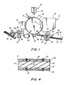
- FIG. 1 depicts schematically the various components thereof.
- FIG. 1 depicts schematically the various components thereof.
- like reference numerals will be employed throughout to designate identical elements.
- the apparatus of the present invention is disclosed as a means for charging a photosensitive member or for discharging a dielectric body, it should be understood that the invention could be used in an electrophotographic environment as a transfer device also.
- a drum 10 having a photoconductive surface 12 coated securely onto the exterior circumferential surface of a conductive substrate is rotated in the direction of arrow 14 through the various processing stations.
- photoconductive surface 12 may be made from selenium of the type described in U.S. Patent 2,970,906.
- a suitable conductive substrate is made from aluminum.
- drum 10 rotates a portion of photoconductive surface 12 through charging station A.
- Charging station A employs a corona generating device in accordance with the present invention, indicated generally by the reference numeral 16, to charge photoconductive surface 12 to a relatively high substantially uniform potential.
- Exposure station B includes an exposure mechanism, indicated generally by the reference numeral 18, having a stationary, transparent platen, such as a glass plate or the like for supporting an original document thereon. Lamps illuminate the original document. Scanning of the original document is achieved by oscillating a mirror in a timed relationship with the movement of drum 10 or by translating the lamps and lens across the original document so as to create incremental light images which are projected through an apertured slit onto the charged portion of photoconductive surface 12. Irradiation of the charged portion of photoconductive surface 12 records an electrostatic latent image corresponding to the information areas contained within the original document.
- Drum 10 rotates the electrostatic latent image recorded on photoconductive surface 12 to development station C.
- Development station C includes a developer unit, indicated generally by the reference numeral 20, having a housing with a supply of developer mix contained therein.
- the developer mix comprises carrier granules with toner particles adhering triboelectrically thereto.
- the carrier granules are formed from a magnetic material with the toner particles being made from a heat fuseable plastic.
- Developer unit 20 is preferably a magnetic brush development system. A system of this type moves the developer mix through a directional flux field to form a brush thereof.
- the electrostatic latent image recorded on photoconductive surface 12 is developed by bringing the brush of developer mix into contact therewith. In this manner, the toner particles are attracted electrostatically from the carrier granules to the latent image forming a toner powder image on photoconductive surface 12.
- a copy sheet is advanced by sheet feeding apparatus 35 to transfer station D.
- Sheet feed apparatus 35 advances successive copy sheets to forwarding registration rollers 23 and 27.
- Forwarding registration roller 23 is driven conventionally by a motor (not shown) in the direction of arrow 38 thereby also rotating idler roller 27 which is in contact therewith in the direction of arrow 39.
- feed device 35 operates to advance the uppermost substrate or sheet from stack 30 into registration rollers 23 and 27 and against registration fingers 24.
- Fingers 24 are actuated by conventional means in timed relation to an image on drum 12 such that the sheet resting against the fingers is forwarded toward the drum in synchronism with the image on the drum.
- a conventional registration finger control system is shown in US-A-3,902,715 to which reference is invited. After the sheet is released by finger 24, it is advanced through a chute formed by guides 28 and 40 to transfer station D.
- transfer station D includes a corona generating device 42 which is the same as corona device 16 and applies a spray of ions to the back side of the copy sheet. This attracts the toner powder image from photoconductive surface 12 to the copy sheet.
- the sheet After transfer of the toner powder image to the copy sheet, the sheet is advanced by endless belt conveyor 44, in the direction of arrow 43, to fusing station E.
- Fusing station E includes a fuser assembly indicated generally by the reference numeral 46.
- Fuser assembly 46 includes a fuser roll 48 and a backup roll 49 defining a nip therebetween through which the copy sheet passes. After the fusing process is completed, the copy sheet is advanced by conventional rollers 52 to catch tray 54.
- Cleaning station F includes a corona generating device (not shown) adapted to neutralize the remaining electrostatic charge on photoconductive surface 12 and that of the residual toner particles.
- the neutralized toner particles are then cleaned from photoconductive surface 12 by a rotatably mounted fibrous brush (not shown) in contact therewith.
- a discharge lamp (not shown) floods photoconductive surface 12 with light to dissipate any residual electrostatic charge remaining thereon prior to the charging thereof for the next successive imaging cycle.
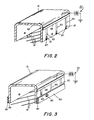
- FIG. 2 depicts the corona generating device 16 in greater detail.
- Corona generating units 16 and 42 are constructed similarly.
- the corona device of this invention could be placed over transport belt 44 and used as a discharge means if desired.
- A.C. voltage with a D.C. bias that would charge the photoreceptor to about the D.C. bias could be used if desired.
- the corona generating unit is positioned above the photosensitive surface 12 and is arranged to deposit an electrical charge thereon as the surface 12 moves in a clockwise direction.
- the corona unit includes a block member that has an insulative shield member 82 which is rectangular in shape and has corona generator wires or coronodes 81 attached thereto.
- a slit or channel opening is formed in the bottom of the insulative shield member 82 opposite the moving photosensitive member and provides a path by which a flow of ions discharged by the generator are directed towards and deposited upon photosensitive surface 12.
- the corona generating wires 81 are individually and separately connected through individual high voltage impedance means to a high potential source or power supply 90 through a bus ',Jar or conducting line 86.
- This power supply which could be positive or negative, supplies a much lower voltage than conventional corona generator power supplies and, as a result, aids in reducing arcing.
- individual wires 81 have impedances or resistances separately connected thereto as well as low capacitance to insure that arcing will not occur, which would damage the photoconductor.
- the capacitance of the wires to the photoreceptor is controlled to the point that the corona charging device requires no shield to provide threshold corona emissions or maintain corona fields.
- the voltage gradients are provided by the presence of the photoconductor; therefore, no shield is required and, as a result, there is no loss of the current to the shield. All current is used for charging, providing 100% charging effectiveness.
- the resistance is in series with each individual wire.
- the small wire to shield and wire to photoconductor dimensions disclosed therein require precise alignment of the corotron wire to a semicircular cavity.
- the wire is as long as the photoconductor is wide which allows for some singing and sagging possibilities which are more detrimental for close spacing.
- the minature corotron 16 of the instant invention comprises very short wires 81 that reduce singing and sagging to a minimal level as well as make tensioning of the wires more easily accomplished.
- corona for negative charging tends to be spotty, i.e., emission points are seen at intervals of about 1 cm.
- the wires are angled at an angle from the direction of travel to reduce the effective distance between "hot spots" to d cos 6, where d is the actual distance of separation and e is the angle of the wires relative to the long axis of the unit.
- a wire is helically wound around insulating member 82 which has a U-shaped channel, then cut after tightening to conductive pads 87 each of which is connected to conducting line 86 through resistive strips 83.
- Pads 87 should be as small as possible, consistent with ease of insuring connection to the corona wires 81 pressed into contact with the pads 87.
- Resistive strips 83 can be a screen printed binder film made partially conducting by loading with carbon black particles.
- insulating member 82 might consist of glass, porcelain, alumina, or the like, in which case resistive strips 83 can consist of a glaze of ruthenium oxide in a glass binder, kiln fired onto insulating member 82.
- resistive strips 83 can consist of a glaze of ruthenium oxide in a glass binder, kiln fired onto insulating member 82.
- Each wire segment overlaps with the next just enough to give continuous coverage of the photoreceptor or photoconductor 12 scanning perpendicular to the long axis of the unit. It should be appreciated that other configurations are possible using these principles, such as staggered wire segments.
- an electrometer showed surprisingly uniform potentials along sections of uniform charging speed with the use of a selenium plate or with an aluminum backed 25 ⁇ m (1 mil) Mylar at about 2.5 cms and 25 ems (one and ten inches per second) with 3.3kV on 3.8 pm (1.5 mil) wire.
- a positive strip charged to 1100 and 700 volts, respectively, for the two speeds.
- a negative section charged to 1200 and 800 volts, respectively.
- a coronode wire to receptor spacing of 1.5 mm was used.
- the corotron could be placed only so close to the photoconductor and arcing would occur because the single long wire employed as the corotron has a built in capacitance, therefore, it could arc.
- the individual impedances and the short wires allow for closer spacing between the photoreceptor and corona wire without arcing.
- Some of the advantages of the corona charging device of the present invention include the use of a low voltage to the coronodes or wires 81; the fact that at the photoconductor charges, the difference in voltage between the coronodes and the photoconductor is reducing; and this change in voltage can shut corona off in a controlled fashion; for example, threshold voltages near 2.2kV are needed so that with a 3.2kV to the wires, the photoconductor will charge to 1kV and shut corona off.
- a minature corotron device in which the coronode wires are supported in short segments which are angled to the conventional wire direction.
- the segments are positioned so that their output currents overlap to deliver uniform current along the length of the device. Since the segments span a short distance, singing and sagging are reduced.
- the individual segments are connected to a high voltage source through a conducting line and a resistive material that serves to prevent arcing and resultant damage to the photoconductive surface.
Landscapes
- Physics & Mathematics (AREA)
- Engineering & Computer Science (AREA)
- Plasma & Fusion (AREA)
- General Physics & Mathematics (AREA)
- Electrostatic Charge, Transfer And Separation In Electrography (AREA)
Applications Claiming Priority (2)
| Application Number | Priority Date | Filing Date | Title |
|---|---|---|---|
| US667318 | 1976-03-16 | ||
| US06/667,318 US5028779A (en) | 1984-11-01 | 1984-11-01 | Corona charging device |
Publications (2)
| Publication Number | Publication Date |
|---|---|
| EP0181725A1 true EP0181725A1 (fr) | 1986-05-21 |
| EP0181725B1 EP0181725B1 (fr) | 1989-07-19 |
Family
ID=24677738
Family Applications (1)
| Application Number | Title | Priority Date | Filing Date |
|---|---|---|---|
| EP85307766A Expired EP0181725B1 (fr) | 1984-11-01 | 1985-10-28 | Dispositif de charge à effet corona |
Country Status (7)
| Country | Link |
|---|---|
| US (1) | US5028779A (fr) |
| EP (1) | EP0181725B1 (fr) |
| JP (1) | JPH0677165B2 (fr) |
| BR (1) | BR8505412A (fr) |
| CA (1) | CA1247694A (fr) |
| DE (1) | DE3571709D1 (fr) |
| MX (1) | MX159137A (fr) |
Cited By (5)
| Publication number | Priority date | Publication date | Assignee | Title |
|---|---|---|---|---|
| EP0567069B1 (fr) * | 1992-04-20 | 1996-10-30 | Matsushita Electric Industrial Co., Ltd. | Dispositif de chargement pour l'électrophotographie |
| EP0618668B1 (fr) * | 1993-04-02 | 1996-11-20 | Mitsubishi Denki Kabushiki Kaisha | Dispositif onduleur de puissance |
| EP1832936A3 (fr) * | 2006-02-13 | 2007-09-26 | Sharp Kabushiki Kaisha | Dispositif de charge électrique, et appareil de formation d'image |
| EP1832935A3 (fr) * | 2006-02-13 | 2007-09-26 | Sharp Kabushiki Kaisha | Dispositif de charge de prétransfert et appareil de formation d'image comportant ce dispositif |
| US9635567B2 (en) | 2011-03-09 | 2017-04-25 | Intel Deutschland Gmbh | Communication devices and methods for network signaling |
Families Citing this family (6)
| Publication number | Priority date | Publication date | Assignee | Title |
|---|---|---|---|---|
| US5539501A (en) * | 1995-07-20 | 1996-07-23 | Xerox Corporation | High slope AC charging device having groups of wires |
| DE19713127C1 (de) * | 1997-03-27 | 1998-11-12 | Brueckner Maschbau | Coronaelektroden-Anordnung |
| US5809364A (en) * | 1997-05-19 | 1998-09-15 | Eastman Kodak Company | Instability detection for corona chargers |
| US5987276A (en) * | 1997-11-14 | 1999-11-16 | Xerox Corporation | Charging device having a shield with integral electrical connector |
| US7092659B2 (en) * | 2003-12-31 | 2006-08-15 | Samsung Electronics Co., Ltd. | Discharge methods and systems in electrophotography |
| US20100221043A1 (en) * | 2009-02-27 | 2010-09-02 | Avision Inc. | Screen-controlled scorotron charging device |
Citations (6)
| Publication number | Priority date | Publication date | Assignee | Title |
|---|---|---|---|---|
| DE1195165B (de) * | 1963-04-30 | 1965-06-16 | Fotoclark F Gruen K G | Aufladegeraet fuer mit einer photoleitenden Schicht versehene Folien |
| DE1991340U (de) * | 1966-05-21 | 1968-08-08 | Zanders Feinpapiere G M B H | Elektrostatische vorrichtung zum doppelseitigen aufladen von beschichteten papieren oder anderen flachen materialien in einem arbeitsgang. |
| US3435309A (en) * | 1962-11-27 | 1969-03-25 | Harris Intertype Corp | Corona charging unit |
| US3470417A (en) * | 1966-10-03 | 1969-09-30 | Eastman Kodak Co | Method of altering electrostatic charge on an insulating material |
| DE2109868A1 (de) * | 1970-03-09 | 1971-09-23 | Savin Business Machines Corp | Verfahren und Anordnung zur Regelung der Dichte einer elektrofotografisch hergestellten Kopie |
| US3900735A (en) * | 1971-09-10 | 1975-08-19 | Hoechst Ag | Corona discharge apparatus |
Family Cites Families (14)
| Publication number | Priority date | Publication date | Assignee | Title |
|---|---|---|---|---|
| US2576047A (en) * | 1948-10-21 | 1951-11-20 | Battelle Development Corp | Method and apparatus for printing electrically |
| US2956847A (en) * | 1954-06-14 | 1960-10-18 | Daub Rudolph | Piston head structure |
| US2881470A (en) * | 1954-12-13 | 1959-04-14 | Olin Mathieson | Apparatus for treating plastic material with electric glow discharge |
| US2836725A (en) * | 1956-11-19 | 1958-05-27 | Haloid Co | Corona charging device |
| US3233156A (en) * | 1961-06-07 | 1966-02-01 | Eastman Kodak Co | Electrostatic charging methods and apparatus |
| US3307034A (en) * | 1963-12-09 | 1967-02-28 | Xerox Corp | Two-wire corona discharge system for single-step electrostatic image formation |
| GB1063913A (en) * | 1965-02-01 | 1967-04-05 | Pentacon Dresden Veb | Device for charging electro-photographic layers |
| DE1522657C3 (de) * | 1966-12-27 | 1973-09-20 | Lumoprint Zindler Kg, 2000 Hamburg | Aufladevorrichtung fur ein elektro statisches Kopiergerat |
| US3527941A (en) * | 1968-07-22 | 1970-09-08 | Eastman Kodak Co | Charging system for placing a uniform charge on a photoconductive surface |
| BE793227A (fr) * | 1971-12-23 | 1973-06-22 | Xerox Corp | Generateur d'effet corona et procede de production de celui-ci |
| JPS5217125Y2 (fr) * | 1972-05-19 | 1977-04-18 | ||
| US4110024A (en) * | 1976-05-14 | 1978-08-29 | Xerox Corporation | Transfer assembly for electrostatic transfer of a toner image from a curvilinear recording surface |
| FR2415528A1 (fr) * | 1978-01-25 | 1979-08-24 | Cellophane Sa | Amelioration aux procedes de fabrication de films par placage electrostatique |
| US4306271A (en) * | 1980-09-24 | 1981-12-15 | Coulter Systems Corporation | Sequentially pulsed overlapping field multielectrode corona charging method and apparatus |
-
1984
- 1984-11-01 US US06/667,318 patent/US5028779A/en not_active Expired - Fee Related
-
1985
- 1985-10-24 JP JP60238546A patent/JPH0677165B2/ja not_active Expired - Lifetime
- 1985-10-28 EP EP85307766A patent/EP0181725B1/fr not_active Expired
- 1985-10-28 DE DE8585307766T patent/DE3571709D1/de not_active Expired
- 1985-10-30 BR BR8505412A patent/BR8505412A/pt not_active IP Right Cessation
- 1985-10-30 CA CA000494209A patent/CA1247694A/fr not_active Expired
- 1985-10-30 MX MX453A patent/MX159137A/es unknown
Patent Citations (6)
| Publication number | Priority date | Publication date | Assignee | Title |
|---|---|---|---|---|
| US3435309A (en) * | 1962-11-27 | 1969-03-25 | Harris Intertype Corp | Corona charging unit |
| DE1195165B (de) * | 1963-04-30 | 1965-06-16 | Fotoclark F Gruen K G | Aufladegeraet fuer mit einer photoleitenden Schicht versehene Folien |
| DE1991340U (de) * | 1966-05-21 | 1968-08-08 | Zanders Feinpapiere G M B H | Elektrostatische vorrichtung zum doppelseitigen aufladen von beschichteten papieren oder anderen flachen materialien in einem arbeitsgang. |
| US3470417A (en) * | 1966-10-03 | 1969-09-30 | Eastman Kodak Co | Method of altering electrostatic charge on an insulating material |
| DE2109868A1 (de) * | 1970-03-09 | 1971-09-23 | Savin Business Machines Corp | Verfahren und Anordnung zur Regelung der Dichte einer elektrofotografisch hergestellten Kopie |
| US3900735A (en) * | 1971-09-10 | 1975-08-19 | Hoechst Ag | Corona discharge apparatus |
Non-Patent Citations (2)
| Title |
|---|
| IBM TECHNICAL DISCLOSURE BULLETIN, vol. 11, no. 5, October 1968, page 475, New York, US; R.M. SCHAFFERT: "Corona charging device" * |
| RESEARCH DISCLOSURE, vol. 185, September 1979, page 504, no. 18543, Havant, Hampshire, GB; J. FISKE et al.: "Grid-controlled corona charger" * |
Cited By (6)
| Publication number | Priority date | Publication date | Assignee | Title |
|---|---|---|---|---|
| EP0567069B1 (fr) * | 1992-04-20 | 1996-10-30 | Matsushita Electric Industrial Co., Ltd. | Dispositif de chargement pour l'électrophotographie |
| EP0618668B1 (fr) * | 1993-04-02 | 1996-11-20 | Mitsubishi Denki Kabushiki Kaisha | Dispositif onduleur de puissance |
| EP1832936A3 (fr) * | 2006-02-13 | 2007-09-26 | Sharp Kabushiki Kaisha | Dispositif de charge électrique, et appareil de formation d'image |
| EP1832935A3 (fr) * | 2006-02-13 | 2007-09-26 | Sharp Kabushiki Kaisha | Dispositif de charge de prétransfert et appareil de formation d'image comportant ce dispositif |
| US9635567B2 (en) | 2011-03-09 | 2017-04-25 | Intel Deutschland Gmbh | Communication devices and methods for network signaling |
| US10057755B2 (en) | 2011-03-09 | 2018-08-21 | Intel Deutschland Gmbh | Communication devices and methods for network signaling |
Also Published As
| Publication number | Publication date |
|---|---|
| BR8505412A (pt) | 1986-08-05 |
| JPS61110176A (ja) | 1986-05-28 |
| DE3571709D1 (en) | 1989-08-24 |
| EP0181725B1 (fr) | 1989-07-19 |
| JPH0677165B2 (ja) | 1994-09-28 |
| CA1247694A (fr) | 1988-12-28 |
| US5028779A (en) | 1991-07-02 |
| MX159137A (es) | 1989-04-26 |
Similar Documents
| Publication | Publication Date | Title |
|---|---|---|
| EP0147985B1 (fr) | Dispositif de décharge corona | |
| US3496352A (en) | Self-cleaning corona generating apparatus | |
| EP0274895B1 (fr) | Dispositif corona pour charger | |
| US2965756A (en) | Electrostatic charging apparatus | |
| EP0181725B1 (fr) | Dispositif de charge à effet corona | |
| US4699499A (en) | Image forming apparatus | |
| US3611074A (en) | Corona discharge device | |
| US5184194A (en) | Carrier particle scavenging device | |
| US4673280A (en) | Transfer charge control system | |
| US4558221A (en) | Self limiting mini-corotron | |
| US5701564A (en) | Scavengeless development apparatus including an electroded donor roll having a tri-contact commutator assembly | |
| EP0147206A2 (fr) | Scorotron à enroulement corona segmenté | |
| US5729807A (en) | Optically switched commutator scheme for hybrid scavengeless segmented electroded donor rolls | |
| EP0588552B1 (fr) | Méthode et appareil pour charger une surface photoconductrice à un potentiel uniforme | |
| US3640249A (en) | Transfer apparatus | |
| EP0274894B1 (fr) | Dispositif corona pour charger | |
| GB2139428A (en) | Corona generating apparatus | |
| US5666601A (en) | Resistive ion source charging device | |
| US5105223A (en) | Screened blade scorotron | |
| GB2127230A (en) | Corona discharge device for separating recording paper from image retaining member | |
| JPH08220841A (ja) | 印刷機及び帯電装置 | |
| US5742051A (en) | Micro sized ion generating device | |
| JPS6221168A (ja) | 電子写真装置の感光体 | |
| JPS59208563A (ja) | ミニコロトロン | |
| JPH09218590A (ja) | 画像形成装置 |
Legal Events
| Date | Code | Title | Description |
|---|---|---|---|
| PUAI | Public reference made under article 153(3) epc to a published international application that has entered the european phase |
Free format text: ORIGINAL CODE: 0009012 |
|
| AK | Designated contracting states |
Kind code of ref document: A1 Designated state(s): DE FR GB |
|
| 17P | Request for examination filed |
Effective date: 19861103 |
|
| 17Q | First examination report despatched |
Effective date: 19880422 |
|
| GRAA | (expected) grant |
Free format text: ORIGINAL CODE: 0009210 |
|
| AK | Designated contracting states |
Kind code of ref document: B1 Designated state(s): DE FR GB |
|
| REF | Corresponds to: |
Ref document number: 3571709 Country of ref document: DE Date of ref document: 19890824 |
|
| ET | Fr: translation filed | ||
| PLBE | No opposition filed within time limit |
Free format text: ORIGINAL CODE: 0009261 |
|
| STAA | Information on the status of an ep patent application or granted ep patent |
Free format text: STATUS: NO OPPOSITION FILED WITHIN TIME LIMIT |
|
| 26N | No opposition filed | ||
| PGFP | Annual fee paid to national office [announced via postgrant information from national office to epo] |
Ref country code: FR Payment date: 19981009 Year of fee payment: 14 |
|
| PGFP | Annual fee paid to national office [announced via postgrant information from national office to epo] |
Ref country code: GB Payment date: 19981030 Year of fee payment: 14 |
|
| PGFP | Annual fee paid to national office [announced via postgrant information from national office to epo] |
Ref country code: DE Payment date: 19981106 Year of fee payment: 14 |
|
| PG25 | Lapsed in a contracting state [announced via postgrant information from national office to epo] |
Ref country code: GB Free format text: LAPSE BECAUSE OF NON-PAYMENT OF DUE FEES Effective date: 19991028 |
|
| GBPC | Gb: european patent ceased through non-payment of renewal fee |
Effective date: 19991028 |
|
| PG25 | Lapsed in a contracting state [announced via postgrant information from national office to epo] |
Ref country code: FR Free format text: LAPSE BECAUSE OF NON-PAYMENT OF DUE FEES Effective date: 20000630 |
|
| PG25 | Lapsed in a contracting state [announced via postgrant information from national office to epo] |
Ref country code: DE Free format text: LAPSE BECAUSE OF NON-PAYMENT OF DUE FEES Effective date: 20000801 |
|
| REG | Reference to a national code |
Ref country code: FR Ref legal event code: ST |