EP0181757B1 - Membrandruckwandler - Google Patents
Membrandruckwandler Download PDFInfo
- Publication number
- EP0181757B1 EP0181757B1 EP85308003A EP85308003A EP0181757B1 EP 0181757 B1 EP0181757 B1 EP 0181757B1 EP 85308003 A EP85308003 A EP 85308003A EP 85308003 A EP85308003 A EP 85308003A EP 0181757 B1 EP0181757 B1 EP 0181757B1
- Authority
- EP
- European Patent Office
- Prior art keywords
- diaphragm
- sensor
- shaft
- ring
- cavity
- Prior art date
- Legal status (The legal status is an assumption and is not a legal conclusion. Google has not performed a legal analysis and makes no representation as to the accuracy of the status listed.)
- Expired - Lifetime
Links
- 239000000463 material Substances 0.000 claims description 7
- 239000004593 Epoxy Substances 0.000 claims description 2
- 238000004891 communication Methods 0.000 claims description 2
- 239000012530 fluid Substances 0.000 description 4
- 238000010276 construction Methods 0.000 description 3
- 239000000853 adhesive Substances 0.000 description 2
- 230000001070 adhesive effect Effects 0.000 description 2
- 230000000712 assembly Effects 0.000 description 2
- 238000000429 assembly Methods 0.000 description 2
- 238000005452 bending Methods 0.000 description 2
- 230000006835 compression Effects 0.000 description 2
- 238000007906 compression Methods 0.000 description 2
- 238000007789 sealing Methods 0.000 description 2
- 238000007689 inspection Methods 0.000 description 1
- 238000003754 machining Methods 0.000 description 1
Images
Classifications
-
- F—MECHANICAL ENGINEERING; LIGHTING; HEATING; WEAPONS; BLASTING
- F15—FLUID-PRESSURE ACTUATORS; HYDRAULICS OR PNEUMATICS IN GENERAL
- F15B—SYSTEMS ACTING BY MEANS OF FLUIDS IN GENERAL; FLUID-PRESSURE ACTUATORS, e.g. SERVOMOTORS; DETAILS OF FLUID-PRESSURE SYSTEMS, NOT OTHERWISE PROVIDED FOR
- F15B15/00—Fluid-actuated devices for displacing a member from one position to another; Gearing associated therewith
- F15B15/08—Characterised by the construction of the motor unit
- F15B15/10—Characterised by the construction of the motor unit the motor being of diaphragm type
-
- G—PHYSICS
- G01—MEASURING; TESTING
- G01L—MEASURING FORCE, STRESS, TORQUE, WORK, MECHANICAL POWER, MECHANICAL EFFICIENCY, OR FLUID PRESSURE
- G01L19/00—Details of, or accessories for, apparatus for measuring steady or quasi-steady pressure of a fluent medium insofar as such details or accessories are not special to particular types of pressure gauges
- G01L19/06—Means for preventing overload or deleterious influence of the measured medium on the measuring device or vice versa
- G01L19/0618—Overload protection
-
- G—PHYSICS
- G01—MEASURING; TESTING
- G01L—MEASURING FORCE, STRESS, TORQUE, WORK, MECHANICAL POWER, MECHANICAL EFFICIENCY, OR FLUID PRESSURE
- G01L13/00—Devices or apparatus for measuring differences of two or more fluid pressure values
- G01L13/02—Devices or apparatus for measuring differences of two or more fluid pressure values using elastically-deformable members or pistons as sensing elements
- G01L13/025—Devices or apparatus for measuring differences of two or more fluid pressure values using elastically-deformable members or pistons as sensing elements using diaphragms
-
- G—PHYSICS
- G01—MEASURING; TESTING
- G01L—MEASURING FORCE, STRESS, TORQUE, WORK, MECHANICAL POWER, MECHANICAL EFFICIENCY, OR FLUID PRESSURE
- G01L7/00—Measuring the steady or quasi-steady pressure of a fluid or a fluent solid material by mechanical or fluid pressure-sensitive elements
- G01L7/02—Measuring the steady or quasi-steady pressure of a fluid or a fluent solid material by mechanical or fluid pressure-sensitive elements in the form of elastically-deformable gauges
- G01L7/08—Measuring the steady or quasi-steady pressure of a fluid or a fluent solid material by mechanical or fluid pressure-sensitive elements in the form of elastically-deformable gauges of the flexible-diaphragm type
Definitions
- the invention relates to diaphragm pressure transducers.
- the diaphragm is connected to the sensor beam by a shaft which acts perpendicularly to the diaphragm and to the sensor beam as described for example, in EP-A-2 623 993.
- the diaphragm is protected against damage due to overpressure conditions by means of an 0-ring which contacts the transducer body and seals a fluid filled cavity between the diaphragm and the sensor beam, the incompressible fluid preventing excessive movement of the diaphragm under high differential pressure conditions.
- the 0-ring continues to compress until a mechanical stop integral with the connecting shaft contacts the transducer body to prevent overstres- sing the sensor beam.
- the connecting shaft must be very accurately located relative to the diaphragm, and the 0-ring and the mechanical stop must be accurately positioned on the shaft.
- the O-ring can cause the O-ring to fail to seal properly, which can result in damage to the diaphragm.
- the 0-ring Under extreme conditions of misalignment the 0-ring can become extruded between the mechanical stop and the transducer body resulting in seal failure and thus damage to the diaphragm and/or excessive bending and thus overstress the sensor beam and diaphragm assembly.
- a diaphragm pressure transducer comprising a body, a sensor beam fixed to the body within a first cavity formed therein, a diaphragm attached to a side of the body over a second cavity in communication with the first cavity, and a shaft assembly connecting the diaphragm and the sensor characterised in that the shaft assembly comprises a first element attached to the sensor beam, a second element attached to the diaphragm and rigidifying material connecting the first and second elements.
- the invention thus provides an improved connection between the diaphragm and the sensor.
- the rigidifying material connecting the diaphragm and the sensor beam can eliminate misalignment and potential tolerance stack up problems.
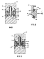
- a pressure transducer 10 comprises abody 12, a sensor 14 fixed to the body 12 within a first cavity 16, a first diaphragm 18 attached at its periphery to the body 12, and a first shaft assembly 20 connecting the first diaphragm 18 and the sensor 14.
- a second diaphragm 19 is attached to the body 12 opposite the first diaphragm 18, and a second shaft assembly 21 connects the second diaphragm and the sensor 14.
- the transducer illustrated herein can be of the kind wherein the sensor 14 defines a beam to which strain gauges (not shown) are attached, and wherein bending forces applied to the beam by the diaphragms are proportional to the differential pressure acting on the diaphragms.
- the shaft assemblies 20 and 21 previously proposed are essentially identical, and only one will be described herein in detail.
- the first shaft assembly 20 is a cylindrical member having a first diameter portion 22 which defines an actuating shaft in contact with the sensor beam 14, asecond relatively large diameter portion 24 having a channel 26 formed therein to receive an 0-ring 28, and a third diameter portion 30 which is attached to the centre of the diaphragm 18.
- the face of the large diameter portion 24 which is defined by its intersection with the first diameter portion 22 defines a mechanical stop surface 32.
- the shaft assembly 20 is received within a second cavity 34 defined by first and second counterbores 36 and 38 respectively formed in the side of the body 12, the diaphragm 18 being received over the counterbore 38.
- the actuating shaft portion 22 extends through a bore 40 formed in the body, which connects the first and second cavities.
- the interconnected cavities 16 and 34 are filled with a fluid. If the differential pressure acting on the right side of the diaphragm 18 exceeds a predetermined level, the O-ring 28 contacts the wall 42 of the cavity 34 thus sealing the cavity, whereby the incompressibility of the fill fluid will resist further movement of the diaphragm. If further excessive force is applied, the stop surface 32 will contact the wall 42 to prevent further movement and possible damage to the sensor.
- the shaft assembly 20 In the previously proposed construction the shaft assembly 20 must be maintained perpendicular to the diaphragm 18, must meet the diaphragm at the proper height, and be concentric with it. Typical tolerances on the position of the shaft are a 0.50 maximum on perpendicularity, ⁇ .05 mm ( ⁇ .002 inches) on height, and ⁇ .127 mm (.005 inches) on concentricity. Because there is a large stack-up of dimensions which contribute to the position of the shaft relative to the diaph- gram, all dimensions must be held to very close tolerances, which results in high machining and inspection costs. The same is true for the positioning of the O-ring 28 and the mechanical stop 32.
- Devices of this type have a typical stroke of .10 mm (.004 inches) with three times permissible overrange of .3 mm (.012 in.) and very slight 0- ring compression of .076 mm (.003 in.) average.
- the 0-ring should not contact the wall within .127 mm (.005 inches) of motion, and the mechanical stop 32 should contact the wall 42 at a maximum of.3 mm (.012 inches) of motion. This leaves a ⁇ .05 mm ( ⁇ .002 inch) tolerance on the height position.
- the O-ring should be parallel to its seat within 0.50.
- Figure 2 illustrates a possible failure mode of the prior art construction. Assuming a 4.57 mm (.180 inch) diameter O-ring for illustration, with the 0-ring being out of parallel with the seat by 1°, when one side of the 0-ring 28 is fully compressed and the stop surface 32 contacts the wall 42, the 0-ring will not have sufficient compression to seal, resulting in possible damage to the diaphragm if an overpressure condition occurs. There is further danger of the O-ring being extruded into the gap between the stop surface 32 and the wall 42, resulting in damage to the 0-ring as well as damage to the diaphragm and possibly to the sensor beam 14.
- the shaft assemblies 120 and 121 are each formed of two parts, a sensor post or stub shaft 122 which is fixed to the sensor beam 14, and an overpressure stop member 124 which includes an extended hollow cylindrical portion 125.
- the opening of the hollow portion and the length of the stub shaft 122 are dimensioned such that the cylindrical portion surrounds the stub shaft 122 with an annular gap therebetween, and there is a space between the end of the stub shaft and the bottom of the cylinder 125.
- the space between the stub shaft and the cylinder wall of the stop member 124 is filled with a rigidifying material 126, for example an epoxy.
- the diaphragms 18 and 19 are attached to the overpressure stop members 124, and the stub shaft 122 is attached to the sensor beam 14.
- the diaphragms and the overpressure stops are set relative to the transducer body, thus cutting a dimensional stack-up chain down to three links and allowing the adhesive joints to compensate for fairly broad variations in the positions of the sensor stub shafts.
- the interior wall of the extended portion 125, and the sensor stub shafts 122 can be threaded, thus increasing the area of adhesion.
Landscapes
- Physics & Mathematics (AREA)
- General Physics & Mathematics (AREA)
- Engineering & Computer Science (AREA)
- Fluid Mechanics (AREA)
- Mechanical Engineering (AREA)
- General Engineering & Computer Science (AREA)
- Measuring Fluid Pressure (AREA)
Claims (4)
Applications Claiming Priority (2)
| Application Number | Priority Date | Filing Date | Title |
|---|---|---|---|
| US06/668,460 US4604900A (en) | 1984-11-05 | 1984-11-05 | Adhesive joint for diaphragm to sensor connection in pressure transducers |
| US668460 | 1984-11-05 |
Publications (3)
| Publication Number | Publication Date |
|---|---|
| EP0181757A2 EP0181757A2 (de) | 1986-05-21 |
| EP0181757A3 EP0181757A3 (en) | 1988-10-12 |
| EP0181757B1 true EP0181757B1 (de) | 1991-01-02 |
Family
ID=24682395
Family Applications (1)
| Application Number | Title | Priority Date | Filing Date |
|---|---|---|---|
| EP85308003A Expired - Lifetime EP0181757B1 (de) | 1984-11-05 | 1985-11-04 | Membrandruckwandler |
Country Status (12)
| Country | Link |
|---|---|
| US (1) | US4604900A (de) |
| EP (1) | EP0181757B1 (de) |
| JP (2) | JPS61114141A (de) |
| KR (1) | KR900000661B1 (de) |
| AU (1) | AU4822385A (de) |
| BR (1) | BR8504764A (de) |
| CA (1) | CA1232773A (de) |
| DE (1) | DE3581057D1 (de) |
| ES (1) | ES289491Y (de) |
| HK (1) | HK31191A (de) |
| IN (1) | IN162906B (de) |
| MX (1) | MX168101B (de) |
Families Citing this family (5)
| Publication number | Priority date | Publication date | Assignee | Title |
|---|---|---|---|---|
| JP4237995B2 (ja) * | 2001-09-28 | 2009-03-11 | コベルコクレーン株式会社 | 自走式クレーン |
| US11291377B2 (en) | 2015-03-31 | 2022-04-05 | California Institute Of Technology | Biocompatible packaging for long term implantable sensors and electronics |
| CN110520031B (zh) | 2017-05-12 | 2023-02-21 | 加州理工学院 | 可植入腔室外压力传感器 |
| FR3075957B1 (fr) * | 2017-12-21 | 2020-01-03 | Arianegroup Sas | Capteur de pression differentiel |
| US11701504B2 (en) | 2020-01-17 | 2023-07-18 | California Institute Of Technology | Implantable intracranial pressure sensor |
Family Cites Families (4)
| Publication number | Priority date | Publication date | Assignee | Title |
|---|---|---|---|---|
| DE2623993B2 (de) * | 1976-05-26 | 1980-05-08 | Siemens Ag, 1000 Berlin Und 8000 Muenchen | Druckdifferenz-Meßgerät |
| DE2935476B2 (de) * | 1979-09-01 | 1981-07-09 | Hottinger Baldwin Messtechnik Gmbh, 6100 Darmstadt | Flüssigkeitsgefüllter Differenzdruckaufnehmer |
| DE3328149A1 (de) * | 1983-08-04 | 1985-02-21 | Eckardt Ag, 7000 Stuttgart | Ueberlastsicherung fuer einen differenzdruckaufnehmer |
| US4543832A (en) * | 1983-09-30 | 1985-10-01 | Transducers, Inc. | Overload protected pressure transducer |
-
1984
- 1984-11-05 US US06/668,460 patent/US4604900A/en not_active Expired - Fee Related
-
1985
- 1985-06-28 CA CA000485890A patent/CA1232773A/en not_active Expired
- 1985-07-02 KR KR1019850004736A patent/KR900000661B1/ko not_active Expired
- 1985-08-22 IN IN610/CAL/85A patent/IN162906B/en unknown
- 1985-09-10 MX MX206568A patent/MX168101B/es unknown
- 1985-09-27 BR BR8504764A patent/BR8504764A/pt not_active IP Right Cessation
- 1985-10-02 AU AU48223/85A patent/AU4822385A/en not_active Abandoned
- 1985-10-09 ES ES1985289491U patent/ES289491Y/es not_active Expired
- 1985-11-01 JP JP60244249A patent/JPS61114141A/ja active Pending
- 1985-11-04 DE DE8585308003T patent/DE3581057D1/de not_active Expired - Fee Related
- 1985-11-04 EP EP85308003A patent/EP0181757B1/de not_active Expired - Lifetime
-
1991
- 1991-04-25 HK HK311/91A patent/HK31191A/en not_active IP Right Cessation
-
1992
- 1992-07-03 JP JP1992052405U patent/JPH0639316Y2/ja not_active Expired - Lifetime
Also Published As
| Publication number | Publication date |
|---|---|
| CA1232773A (en) | 1988-02-16 |
| AU4822385A (en) | 1986-05-15 |
| ES289491Y (es) | 1986-10-01 |
| JPH0630747U (ja) | 1994-04-22 |
| ES289491U (es) | 1986-02-16 |
| BR8504764A (pt) | 1986-07-22 |
| KR860004253A (ko) | 1986-06-20 |
| JPS61114141A (ja) | 1986-05-31 |
| US4604900A (en) | 1986-08-12 |
| EP0181757A3 (en) | 1988-10-12 |
| DE3581057D1 (de) | 1991-02-07 |
| HK31191A (en) | 1991-05-03 |
| EP0181757A2 (de) | 1986-05-21 |
| JPH0639316Y2 (ja) | 1994-10-12 |
| MX168101B (es) | 1993-05-03 |
| IN162906B (de) | 1988-07-23 |
| KR900000661B1 (ko) | 1990-02-02 |
Similar Documents
| Publication | Publication Date | Title |
|---|---|---|
| AU658592B2 (en) | Pressure transmitter with stress isolation depression | |
| US4543832A (en) | Overload protected pressure transducer | |
| US5165281A (en) | High pressure capacitive transducer | |
| US4980675A (en) | Temperature compensatible pressure monitor and sensor construction | |
| DE19882225B4 (de) | Meßwertgeber mit Trenneinheit für Drucksensor | |
| EP0362287A4 (en) | Modular transmitter | |
| US6612179B1 (en) | Method and apparatus for the determination of absolute pressure and differential pressure therefrom | |
| US4309908A (en) | Liquid filled pressure transducer | |
| US6539808B2 (en) | Press-fit remote diaphragm assembly | |
| EP1007925A1 (de) | Schubsensor | |
| WO2019005253A1 (en) | PRESSURE SENSOR ASSEMBLY | |
| EP0181757A2 (de) | Membrandruckwandler | |
| US4135407A (en) | Method and apparatus for overrange protection of the transducer in a differential pressure transmitter | |
| EP4062086A1 (de) | Dichtungsanordnung und dichtelement | |
| CA2145696A1 (en) | Pressure sensor assembly and method of producing the pressure sensor assembly | |
| EP0127776B1 (de) | Halbleiter-Differenzdruckwandler | |
| US5616847A (en) | Sensor for expansion measurement | |
| US5333507A (en) | Pressure sensor and a method for the manufacture thereof | |
| EP0864078A1 (de) | Selbstverstärkende prozessdichtung für prozesssteuerungstransmitter | |
| JPH02222822A (ja) | 回転測定ロール | |
| EP0161929B1 (de) | Balken für Kraftwandler | |
| US6279407B1 (en) | Linkage with capacitive force sensor assembly | |
| KR20220009871A (ko) | 압력 센서 | |
| US4476723A (en) | Density sensor | |
| IE55965B1 (en) | Pressure transducer |
Legal Events
| Date | Code | Title | Description |
|---|---|---|---|
| PUAI | Public reference made under article 153(3) epc to a published international application that has entered the european phase |
Free format text: ORIGINAL CODE: 0009012 |
|
| AK | Designated contracting states |
Kind code of ref document: A2 Designated state(s): DE FR GB IT |
|
| PUAL | Search report despatched |
Free format text: ORIGINAL CODE: 0009013 |
|
| RHK1 | Main classification (correction) |
Ipc: G01L 13/02 |
|
| AK | Designated contracting states |
Kind code of ref document: A3 Designated state(s): DE FR GB IT |
|
| 17P | Request for examination filed |
Effective date: 19890204 |
|
| 17Q | First examination report despatched |
Effective date: 19900514 |
|
| RAP1 | Party data changed (applicant data changed or rights of an application transferred) |
Owner name: INTERNATIONAL CONTROL AUTOMATION FINANCE S.A. |
|
| GRAA | (expected) grant |
Free format text: ORIGINAL CODE: 0009210 |
|
| ITF | It: translation for a ep patent filed | ||
| AK | Designated contracting states |
Kind code of ref document: B1 Designated state(s): DE FR GB IT |
|
| REF | Corresponds to: |
Ref document number: 3581057 Country of ref document: DE Date of ref document: 19910207 |
|
| ET | Fr: translation filed | ||
| PLBE | No opposition filed within time limit |
Free format text: ORIGINAL CODE: 0009261 |
|
| STAA | Information on the status of an ep patent application or granted ep patent |
Free format text: STATUS: NO OPPOSITION FILED WITHIN TIME LIMIT |
|
| 26N | No opposition filed | ||
| PGFP | Annual fee paid to national office [announced via postgrant information from national office to epo] |
Ref country code: FR Payment date: 19961021 Year of fee payment: 12 |
|
| PGFP | Annual fee paid to national office [announced via postgrant information from national office to epo] |
Ref country code: GB Payment date: 19961025 Year of fee payment: 12 |
|
| PGFP | Annual fee paid to national office [announced via postgrant information from national office to epo] |
Ref country code: DE Payment date: 19961028 Year of fee payment: 12 |
|
| PG25 | Lapsed in a contracting state [announced via postgrant information from national office to epo] |
Ref country code: GB Free format text: LAPSE BECAUSE OF NON-PAYMENT OF DUE FEES Effective date: 19971104 |
|
| PG25 | Lapsed in a contracting state [announced via postgrant information from national office to epo] |
Ref country code: FR Free format text: THE PATENT HAS BEEN ANNULLED BY A DECISION OF A NATIONAL AUTHORITY Effective date: 19971130 |
|
| GBPC | Gb: european patent ceased through non-payment of renewal fee |
Effective date: 19971104 |
|
| PG25 | Lapsed in a contracting state [announced via postgrant information from national office to epo] |
Ref country code: DE Free format text: LAPSE BECAUSE OF NON-PAYMENT OF DUE FEES Effective date: 19980801 |
|
| REG | Reference to a national code |
Ref country code: FR Ref legal event code: ST |