EP0181788B1 - Verfahren und Vorrichtung zur Stabilisierung der Schleifgeschwindigkeit des Randes von Brillengläsern auf einer mit Kopiervorrichtung ausgestatteten Maschine - Google Patents
Verfahren und Vorrichtung zur Stabilisierung der Schleifgeschwindigkeit des Randes von Brillengläsern auf einer mit Kopiervorrichtung ausgestatteten Maschine Download PDFInfo
- Publication number
- EP0181788B1 EP0181788B1 EP19850401841 EP85401841A EP0181788B1 EP 0181788 B1 EP0181788 B1 EP 0181788B1 EP 19850401841 EP19850401841 EP 19850401841 EP 85401841 A EP85401841 A EP 85401841A EP 0181788 B1 EP0181788 B1 EP 0181788B1
- Authority
- EP
- European Patent Office
- Prior art keywords
- amplifier
- output
- input
- machine
- lens
- Prior art date
- Legal status (The legal status is an assumption and is not a legal conclusion. Google has not performed a legal analysis and makes no representation as to the accuracy of the status listed.)
- Expired
Links
- 238000000034 method Methods 0.000 title claims description 6
- 230000000087 stabilizing effect Effects 0.000 title description 3
- 238000004519 manufacturing process Methods 0.000 claims 2
- 230000003019 stabilising effect Effects 0.000 claims 1
- 239000011521 glass Substances 0.000 description 19
- 238000003754 machining Methods 0.000 description 6
- 239000003990 capacitor Substances 0.000 description 3
- 230000001276 controlling effect Effects 0.000 description 3
- 230000007423 decrease Effects 0.000 description 2
- 238000010586 diagram Methods 0.000 description 2
- 238000009795 derivation Methods 0.000 description 1
- 230000001105 regulatory effect Effects 0.000 description 1
- 239000000523 sample Substances 0.000 description 1
- 230000006641 stabilisation Effects 0.000 description 1
- 238000011105 stabilization Methods 0.000 description 1
Images

Classifications
-
- B—PERFORMING OPERATIONS; TRANSPORTING
- B24—GRINDING; POLISHING
- B24B—MACHINES, DEVICES, OR PROCESSES FOR GRINDING OR POLISHING; DRESSING OR CONDITIONING OF ABRADING SURFACES; FEEDING OF GRINDING, POLISHING, OR LAPPING AGENTS
- B24B9/00—Machines or devices designed for grinding edges or bevels on work or for removing burrs; Accessories therefor
- B24B9/02—Machines or devices designed for grinding edges or bevels on work or for removing burrs; Accessories therefor characterised by a special design with respect to properties of materials specific to articles to be ground
- B24B9/06—Machines or devices designed for grinding edges or bevels on work or for removing burrs; Accessories therefor characterised by a special design with respect to properties of materials specific to articles to be ground of non-metallic inorganic material, e.g. stone, ceramics, porcelain
- B24B9/08—Machines or devices designed for grinding edges or bevels on work or for removing burrs; Accessories therefor characterised by a special design with respect to properties of materials specific to articles to be ground of non-metallic inorganic material, e.g. stone, ceramics, porcelain of glass
- B24B9/14—Machines or devices designed for grinding edges or bevels on work or for removing burrs; Accessories therefor characterised by a special design with respect to properties of materials specific to articles to be ground of non-metallic inorganic material, e.g. stone, ceramics, porcelain of glass of optical work, e.g. lenses, prisms
- B24B9/144—Machines or devices designed for grinding edges or bevels on work or for removing burrs; Accessories therefor characterised by a special design with respect to properties of materials specific to articles to be ground of non-metallic inorganic material, e.g. stone, ceramics, porcelain of glass of optical work, e.g. lenses, prisms the spectacles being used as a template
Definitions
- the present invention relates to the machining of spectacle lenses on the grinding machines used to cut the blanks.
- the residence time of the various points on the periphery of the glass can vary to a large extent depending on the shape of the glass to be machined, this time being constant only in the case of a glass of circular shape.
- the residence time decreases considerably, because this part remains only a short instant in contact with the grinding wheel, while the parts of angles of the glass remain in contact with the grinding wheel for a time which can in some cases represent up to 1/4 of the glass revolution time.
- the invention therefore aims to provide a method and a device for stabilizing this residence time.
- the invention also relates to a device for implementing this method, characterized in that it comprises a circuit comprising a capacitor in series with the input of an OP amplifier, a resistor in parallel between the input and the output of the amplifier, a rectifier connected to the output of said circuit, and an amplifier-subtractor, one input of which is connected to the output of the rectifier and the other input of which is connected to a circuit providing a stabilized voltage representing the speed maximum machining of the grinding machine, the output of said amplifier-subtractor being applied to a device for controlling the glass drive motor, as known per se.
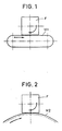
- FIGS. 1 and 2 are diagrams showing the residence time of the different points of the periphery of a square-shaped spectacle lens on an abrasive strip and on a circular grinding wheel; respectively.
- Figure 3 is a diagram of a machine for cutting spectacle lenses comprising a device for regulating the machining speed according to the invention.
- the machine for cutting spectacle lenses comprises a grinding wheel M, a carriage C moving around an axis A and carrying an axis 1 carrying the glass V to be cut and driven by a motor 2.
- the machine also includes a copier designated as a whole by the reference 3 comprising a device 4 for supporting and driving a mount 5 in rotation, a feeler 6 whose head is in contact with the bottom of the bezel, this feeler being mounted on a sliding support 7 resiliently recalled and connected to a potentiometer 8, this assembly being known per se.
- a copier designated as a whole by the reference 3 comprising a device 4 for supporting and driving a mount 5 in rotation, a feeler 6 whose head is in contact with the bottom of the bezel, this feeler being mounted on a sliding support 7 resiliently recalled and connected to a potentiometer 8, this assembly being known per se.
- an electronic device E comprising a capacitor 9 in series with an amplifier OP 10, a resistor 11 in derivation of the amplifier 10, a rectifier 12 connected to the output of the amplifier 10, and an amplifier subtractor 13, one input of which is connected to the output of rectifier 12 and the other input of which is connected to a circuit 14 providing a stabilized reference voltage.
- the output signal from the potentiometer 8 representing the movement of the mount 5 is applied to the circuit comprising the capacitor 9, the amplifier 10 and the resistor 11, and the output of the amplifier 10 provides the absolute value of the derivative, that is to say the speed of variation of the rays of the desired lens measured by the probe 6 on the internal periphery of the bezel of the frame.
- This absolute value is rectified by the rectifier 12 and is applied to a first input of the amplifier-subtractor 13, the other input of which receives a stabilized voltage supplied by the circuit 14 and representative of the maximum machining speed of the machine.
- the output signal of the amplifier 13 is then applied to a known device, not shown, for controlling the motor 2 to drive the latter and obtain stabilization of the residence time of the different points of the periphery of a spectacle lens. on the machine wheel.
Landscapes
- Engineering & Computer Science (AREA)
- Chemical & Material Sciences (AREA)
- Ceramic Engineering (AREA)
- Inorganic Chemistry (AREA)
- Mechanical Engineering (AREA)
- Grinding And Polishing Of Tertiary Curved Surfaces And Surfaces With Complex Shapes (AREA)
- Constituent Portions Of Griding Lathes, Driving, Sensing And Control (AREA)
Claims (2)
Applications Claiming Priority (2)
| Application Number | Priority Date | Filing Date | Title |
|---|---|---|---|
| FR8417115A FR2573225B1 (fr) | 1984-11-09 | 1984-11-09 | Procede et dispositif pour stabiliser la vitesse de meulage de la peripherie des verres de lunettes sur une machine comportant une copieuse |
| FR8417115 | 1984-11-09 |
Publications (2)
| Publication Number | Publication Date |
|---|---|
| EP0181788A1 EP0181788A1 (de) | 1986-05-21 |
| EP0181788B1 true EP0181788B1 (de) | 1988-03-02 |
Family
ID=9309439
Family Applications (1)
| Application Number | Title | Priority Date | Filing Date |
|---|---|---|---|
| EP19850401841 Expired EP0181788B1 (de) | 1984-11-09 | 1985-09-23 | Verfahren und Vorrichtung zur Stabilisierung der Schleifgeschwindigkeit des Randes von Brillengläsern auf einer mit Kopiervorrichtung ausgestatteten Maschine |
Country Status (4)
| Country | Link |
|---|---|
| EP (1) | EP0181788B1 (de) |
| JP (1) | JPS61293763A (de) |
| DE (1) | DE3561697D1 (de) |
| FR (1) | FR2573225B1 (de) |
Families Citing this family (3)
| Publication number | Priority date | Publication date | Assignee | Title |
|---|---|---|---|---|
| FR2614690B1 (fr) * | 1987-04-28 | 1990-11-09 | Essilor Int | Appareil de lecture de contour, notamment pour monture de lunettes |
| FR2652893B1 (fr) * | 1989-10-06 | 1993-03-19 | Essilor Int | Appareil de lecture de contour, notamment pour monture de lunettes. |
| CN110497255B (zh) * | 2019-08-30 | 2020-07-28 | 西安交通大学 | 一种自由曲面抛光驻留时间计算方法 |
Family Cites Families (9)
| Publication number | Priority date | Publication date | Assignee | Title |
|---|---|---|---|---|
| FR519016A (fr) * | 1920-06-21 | 1921-06-03 | Standard Optical Co | Machine servant à meuler les bords des verres d'optique |
| FR1441057A (fr) * | 1965-07-08 | 1966-06-03 | Fujitsu Ltd | Machine pour le meulage d'une came commandée suivant des données numériques |
| JPS4915946B1 (de) * | 1970-08-03 | 1974-04-18 | ||
| DE2332001C3 (de) * | 1972-06-28 | 1980-07-10 | Robert Raymond Maurice Asselin | Randschleifmaschine für Brillengläser |
| FR2229213A6 (en) * | 1973-05-09 | 1974-12-06 | Asselin Robert | Optical lense grinder - with copying mechanism for spectacle rim |
| DE2712029C3 (de) * | 1977-03-18 | 1983-04-07 | Mitsubishi Jukogyo K.K., Tokyo | Nockenschleifmaschine |
| JPS555222A (en) * | 1978-06-20 | 1980-01-16 | Toyoda Mach Works Ltd | Revolving speed controller for work in cam grinder |
| GB2092489B (en) * | 1981-02-05 | 1984-06-06 | Hoya Lens Corp | Apparatus for cutting peripheral groove on spectacle lens |
| JPS5845854A (ja) * | 1981-09-10 | 1983-03-17 | Nippon Kogaku Kk <Nikon> | 眼鏡レンズ用玉摺機 |
-
1984
- 1984-11-09 FR FR8417115A patent/FR2573225B1/fr not_active Expired
-
1985
- 1985-09-23 EP EP19850401841 patent/EP0181788B1/de not_active Expired
- 1985-09-23 DE DE8585401841T patent/DE3561697D1/de not_active Expired
- 1985-10-31 JP JP24300785A patent/JPS61293763A/ja active Pending
Also Published As
| Publication number | Publication date |
|---|---|
| FR2573225A1 (fr) | 1986-05-16 |
| DE3561697D1 (en) | 1988-04-07 |
| EP0181788A1 (de) | 1986-05-21 |
| JPS61293763A (ja) | 1986-12-24 |
| FR2573225B1 (fr) | 1987-02-06 |
Similar Documents
| Publication | Publication Date | Title |
|---|---|---|
| EP0290546B1 (de) | Werkstückträgerspindel mit magnetischen lagern und vorrichtung zum verwenden dieser in einer hochpräzisen werkzeugmaschinen | |
| EP0289575B1 (de) | Verfahren zur ultra-präzisen bearbeitung von untypischen rotationsflächen und selbststeuernde bearbeitung | |
| FR2600001A1 (fr) | Dispositif pour la commande de la vitesse d'avance d'un outil vers une piece a usiner | |
| FR2628906A1 (fr) | Dispositif de mise en forme et d'exploitation des ondulations de courant d'induit generees par un moteur a courant continu, notamment pour commande de positionnement | |
| EP0374606B1 (de) | Verfahren und Vorrichtung zum winkeligen Einstellen eines Werkstückes auf einer Werkzeugmaschine mittels eines Laserstrahles | |
| FR2847212A1 (fr) | Appareil de reglage de direction d'eclairage d'un phare de vehicule | |
| EP0281480A1 (de) | Maschinen zum Kantenschleifen von ophthalmischen Gläsern | |
| EP0181788A1 (de) | Verfahren und Vorrichtung zur Stabilisierung der Schleifgeschwindigkeit des Randes von Brillengläsern auf einer mit Kopiervorrichtung ausgestatteten Maschine | |
| FR2697769A1 (fr) | Machine automatique pour meuler et biseauter les verres ophtalmiques. | |
| EP0168311B1 (de) | Schleifmaschine mit einem Regelkreis zum Positionieren des Werkzeugschlittens | |
| FR2467384A1 (fr) | Procede et appareil pour controler la precision d'un contour usine dans une piece | |
| FR2525138A1 (fr) | Appareil d'usinage de lentilles optiques | |
| EP0114141A2 (de) | Verfahren zur automatischen Steuerung einer Schleifmaschine mit drehbarem Schleifkopf zum Schleifen von Glasplattenrändern und Vorrichtung zur Anwendung desselben | |
| FR2635288A1 (fr) | Procede pour fabriquer un article possedant une forme aspherique et dispositif pour la mise en oeuvre de ce procede | |
| EP0020211B1 (de) | Vorrichtung zur Geschwindigkeitsregelung | |
| FR2633541A1 (fr) | Dispositif pour perforer des objets en forme de tige | |
| CH620033A5 (de) | ||
| FR2528745A1 (fr) | Procede pour deplacer tridimensionnellement un outil et machine-outil pour sa mise en oeuvre | |
| EP0257164B1 (de) | Einrichtung zur relativen Positionierung eines Werkzeuges und eines Werkstückes | |
| EP0085603A1 (de) | Verfahren und Vorrichtung zur Programmierung einer Bearbeitungsmaschine mit beweglichem, zwei Richtungen folgendem Wagen | |
| FR2499442A1 (fr) | Appareil de decoupe pour effectuer une gorge sur des verres de lunette | |
| EP0811448B1 (de) | Regelvorrichtung der Position einer Bearbeitungsspindel | |
| FR2808136A1 (fr) | Procede et dispositif pour la commande amelioree de moteurs et d'un dispositif de travail actionne par un moteur | |
| FR2512725A1 (fr) | Perfectionnement aux contrepointes de rectifieuses cylindriques | |
| FR1465710A (fr) | Dispositif suiveur d'un profil ou tracé plan |
Legal Events
| Date | Code | Title | Description |
|---|---|---|---|
| PUAI | Public reference made under article 153(3) epc to a published international application that has entered the european phase |
Free format text: ORIGINAL CODE: 0009012 |
|
| 17P | Request for examination filed |
Effective date: 19850924 |
|
| AK | Designated contracting states |
Kind code of ref document: A1 Designated state(s): BE DE GB IT LU NL |
|
| 17Q | First examination report despatched |
Effective date: 19870720 |
|
| ITF | It: translation for a ep patent filed | ||
| GRAA | (expected) grant |
Free format text: ORIGINAL CODE: 0009210 |
|
| AK | Designated contracting states |
Kind code of ref document: B1 Designated state(s): BE DE GB IT LU NL |
|
| GBT | Gb: translation of ep patent filed (gb section 77(6)(a)/1977) | ||
| REF | Corresponds to: |
Ref document number: 3561697 Country of ref document: DE Date of ref document: 19880407 |
|
| PLBE | No opposition filed within time limit |
Free format text: ORIGINAL CODE: 0009261 |
|
| STAA | Information on the status of an ep patent application or granted ep patent |
Free format text: STATUS: NO OPPOSITION FILED WITHIN TIME LIMIT |
|
| 26N | No opposition filed | ||
| ITTA | It: last paid annual fee | ||
| EPTA | Lu: last paid annual fee | ||
| PGFP | Annual fee paid to national office [announced via postgrant information from national office to epo] |
Ref country code: LU Payment date: 19940901 Year of fee payment: 10 |
|
| PGFP | Annual fee paid to national office [announced via postgrant information from national office to epo] |
Ref country code: NL Payment date: 19940930 Year of fee payment: 10 |
|
| PG25 | Lapsed in a contracting state [announced via postgrant information from national office to epo] |
Ref country code: LU Free format text: LAPSE BECAUSE OF NON-PAYMENT OF DUE FEES Effective date: 19950923 |
|
| PG25 | Lapsed in a contracting state [announced via postgrant information from national office to epo] |
Ref country code: NL Effective date: 19960401 |
|
| NLV4 | Nl: lapsed or anulled due to non-payment of the annual fee |
Effective date: 19960401 |
|
| PGFP | Annual fee paid to national office [announced via postgrant information from national office to epo] |
Ref country code: DE Payment date: 19960821 Year of fee payment: 12 |
|
| PGFP | Annual fee paid to national office [announced via postgrant information from national office to epo] |
Ref country code: GB Payment date: 19960917 Year of fee payment: 12 |
|
| PGFP | Annual fee paid to national office [announced via postgrant information from national office to epo] |
Ref country code: BE Payment date: 19961009 Year of fee payment: 12 |
|
| PG25 | Lapsed in a contracting state [announced via postgrant information from national office to epo] |
Ref country code: GB Free format text: LAPSE BECAUSE OF NON-PAYMENT OF DUE FEES Effective date: 19970923 |
|
| PG25 | Lapsed in a contracting state [announced via postgrant information from national office to epo] |
Ref country code: BE Free format text: LAPSE BECAUSE OF NON-PAYMENT OF DUE FEES Effective date: 19970930 |
|
| BERE | Be: lapsed |
Owner name: BRIOT INTERNATIONAL Effective date: 19970930 |
|
| GBPC | Gb: european patent ceased through non-payment of renewal fee |
Effective date: 19970923 |
|
| PG25 | Lapsed in a contracting state [announced via postgrant information from national office to epo] |
Ref country code: DE Free format text: LAPSE BECAUSE OF NON-PAYMENT OF DUE FEES Effective date: 19980603 |