EP0181834A2 - Corps de boussole - Google Patents
Corps de boussole Download PDFInfo
- Publication number
- EP0181834A2 EP0181834A2 EP85810490A EP85810490A EP0181834A2 EP 0181834 A2 EP0181834 A2 EP 0181834A2 EP 85810490 A EP85810490 A EP 85810490A EP 85810490 A EP85810490 A EP 85810490A EP 0181834 A2 EP0181834 A2 EP 0181834A2
- Authority
- EP
- European Patent Office
- Prior art keywords
- bearing
- magnetic compass
- compass body
- body according
- magnetic
- Prior art date
- Legal status (The legal status is an assumption and is not a legal conclusion. Google has not performed a legal analysis and makes no representation as to the accuracy of the status listed.)
- Granted
Links
Images



Classifications
-
- G—PHYSICS
- G01—MEASURING; TESTING
- G01C—MEASURING DISTANCES, LEVELS OR BEARINGS; SURVEYING; NAVIGATION; GYROSCOPIC INSTRUMENTS; PHOTOGRAMMETRY OR VIDEOGRAMMETRY
- G01C17/00—Compasses; Devices for ascertaining true or magnetic north for navigation or surveying purposes
- G01C17/02—Magnetic compasses
- G01C17/04—Magnetic compasses with north-seeking magnetic elements, e.g. needles
Definitions
- Magnetic compasses have been steadily improved in recent years, particularly as a result of increasingly stringent military regulations and the increasing number of orienteers, but even top-of-the-range products still have some disadvantages, such as limiting the position of the needle in the case of strong inclinations and a relative one long damping time, which can lead to difficulties especially for orienteers.
- Another task is to specify a magnetic compass body in which the declination can be set precisely and easily.
- FIG. 1 shows the magnetic compass body 1 assembled as a unit, with an upper and lower cover glass 2 and 3, the side wall 4 and the rotatable bearing 6 with the pointer arrangement 7.
- the holder 8 of the bearing pin 9 and above the adjusting knob 10 can also be seen to set the declination.
- the lower part 11 of the side wall has a larger diameter and a corrugation 12 in order to be able to easily turn the compass body relative to the compass housing (not shown), the compass body being guided on the compass housing by means of the groove 5.
- the side wall 4 in FIG. 1 has two mirrored surfaces 50 inclined at 45 °, with which it is possible to project characters or scale parts which are attached to the surface of the cap 28 of the bearing 6 onto the cover glasses 2 and 3 . Among other things, this enables the declination to be set precisely.
- a ring or individual elements 40 in the side wall 4 of the compass body, which can be filled with a luminous gas such as tritium.
- FIG. 3 shows a first exemplary embodiment of a bearing for a display device of a magnetic compass on an enlarged scale.
- the bearing 6, as a cylindrical body with outer sides tapering from the center, is suspended on the bearing pin 9, which has a ball 19 at its upper end, generally made of sapphire or ruby or hardened, non-magnetic steel.
- the counter bearing is formed from a ball bearing 20, which is arranged semi-spherically around the bearing ball 19.
- the hemispherical ball bearing cage 41 is inserted in an inner housing piece 21 and held by a closure part 22.
- the magnet 23 is embedded in the center of the inner housing piece, it being possible to use a relatively small magnetic mass with the strongly magnetic materials available, such as, for example, samarium-cobalt or other rare-earth-cobalt alloys or metallic glasses.
- the ball bearing cage 41 and the closure part 22 form a bearing part 43 which can be made for itself and inserted into the magnetic mass 23.
- pivot pins 44 are arranged which form a tilt axis 42 which runs perpendicular to the longitudinal direction of the bearing pin and through the center of the bearing tip 19.
- the tilt axis runs exactly in the east-west direction, so that the inclination is always automatically compensated for, regardless of its value, and an accurate reading and correct setting of the pointer arrangement is guaranteed, even in countries that are close to the south or north pole are.
- FIGS. 6 and 7 show two variants of the insertable bearing part 43.
- the bearing part 43 is made of metal or a suitable plastic and has a parabolic surface 45 on the inside, on which the tip 46 of the bearing pin 9 runs.
- the bearing part 43 according to FIG. 7 likewise has a parabolic inner surface 47, a bearing block 48 being embedded in the apex surface thereof with a likewise parabolic inner surface on which the tip 46 of the bearing pin runs. It is possible to use additional counter bearing surfaces on the bearing part and to design the bearing tip accordingly.
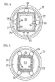
- the inner housing piece 21 is U-shaped in cross section, the outer wall 25 need not be cylindrical as shown, but can be quadrangular or polygonal, while the inner wall 24 is square in this embodiment.
- the two walls 24 and 25 form a damping chamber 27, in which, below the suspension point, several weight compensation cylinders 26 are arranged, which serve for the most precise compensation and balancing of the bearing on the bearing pin. These compensation cylinders can each be arranged at the center of the side according to FIG. 4 or at the corners according to FIG. 5.
- the damping chamber 27 can be filled with a liquid or mercury and is completely vapor and gas tight, so that no vapors or gases can escape.
- the pointer arrangement 7 By installing a closed damping chamber, which is also un can be divided, a quick and good damping of the bearing and thus the pointer arrangement can be achieved.
- the cap 28 preferably made of plastic, with tapering outer sides, the pointer arrangement 7 being embedded in this cap and secured by pins 29.
- a locking and adjusting device 30 which cooperates with the setting button 10.
- a central axis 31 can be seen, which is provided at the top with a cone 32 and in the middle with a gearwheel 33 which meshes with two gearwheels 34 and 35, which each rotate about an axis 36 and 37.
- the two outer gears mesh with a ring gear 38 embedded in the upper part of the cap.
- the conical opening 39 grips the cone 32 and fixes the bearing 6 and the pins 105 engage in corresponding openings 106 in the gear 33.
- the gears and then the ring gear 38 are rotated, ie the whole bearing 6 with the movable scale.
- Such an adjustment device makes it possible to attach a corresponding scale for the most important places on earth and to set the absolute north direction and the declination very precisely.
- the U-shaped part of the inner body part can be completely filled with a brake fluid, for example oil or mercury, whereby this fluid can also be under a certain gas pressure and this gas can be a luminous gas such as tritium. It is also possible to design the magnet directly as a holder for the ball bearing cage, which can save height and weight.
- a brake fluid for example oil or mercury
- the mirrored surfaces parabolic or otherwise designed and to use the bottom as a reflecting surface instead of the lower cover glass 3.
- the cap of the mounting can be spherical or hemispherical on the outside.
- the pointers have been completely omitted and all information relating to the mounting is projected onto or through the body.
- the body 59 is designed as a closed box in which there is mercury 60 that contracts into a hemisphere under the pressure of a filling gas, which can be tritium, for example.
- a bearing pin 61 is arranged in the housing, on which the bearing 62 is attached, in the lower side 63 of which a bearing block 64 is embedded.
- the geometry of the bore of this bearing block which is adapted to the bearing pin, determines the degree of freedom of the bearing in the vertical direction, i.e. regarding the inclination, which can also be automatically compensated.
- the lower part of the bearing is provided with a magnetic mass 65.
- the movable scale is attached to the outside 58 of the bearing and can either be transmitted through windows in the body or the whole body is made of a transparent material. It is important that even in the event of a shock or if the situation is reversed, no mercury can penetrate into the cavity of the bearing. This must be prevented with an appropriate back pressure or with a correct capillary play.
- the body 66 can be seen in FIG. 9, for example a transparent material, the bearing pin 67 and the bearing 68, the scale being attached to the outside of the side walls 69.
- the magnetic mass 70 is located in the bearing.
- the opening 71 in the holder base 72, or the bore of a bearing block, is rounded off, so that the free-hanging bearing 68 can incline according to the inclination vector and can swing inclined on the ball bed 73 about its axis of rotation, around the Compensate inclination.
- the ball bed 73 is embedded in a ball bed socket 74.
- the body can be filled with a luminous gas, for example tritium.
- the bodies 59 and 66 according to FIGS. 8 and 9 are particularly suitable as part of precise measuring instruments.
Landscapes
- Engineering & Computer Science (AREA)
- Radar, Positioning & Navigation (AREA)
- Remote Sensing (AREA)
- Physics & Mathematics (AREA)
- General Physics & Mathematics (AREA)
- Magnetic Bearings And Hydrostatic Bearings (AREA)
- Pivots And Pivotal Connections (AREA)
Priority Applications (1)
| Application Number | Priority Date | Filing Date | Title |
|---|---|---|---|
| AT85810490T ATE70630T1 (de) | 1984-10-29 | 1985-10-28 | Magnetkompass-koerper. |
Applications Claiming Priority (2)
| Application Number | Priority Date | Filing Date | Title |
|---|---|---|---|
| EP84810518 | 1984-10-29 | ||
| EP84810518 | 1984-10-29 |
Publications (3)
| Publication Number | Publication Date |
|---|---|
| EP0181834A2 true EP0181834A2 (fr) | 1986-05-21 |
| EP0181834A3 EP0181834A3 (en) | 1989-03-29 |
| EP0181834B1 EP0181834B1 (fr) | 1991-12-18 |
Family
ID=8193049
Family Applications (1)
| Application Number | Title | Priority Date | Filing Date |
|---|---|---|---|
| EP85810490A Expired - Lifetime EP0181834B1 (fr) | 1984-10-29 | 1985-10-28 | Corps de boussole |
Country Status (2)
| Country | Link |
|---|---|
| EP (1) | EP0181834B1 (fr) |
| DE (1) | DE3584947D1 (fr) |
Cited By (2)
| Publication number | Priority date | Publication date | Assignee | Title |
|---|---|---|---|---|
| EP0485681A1 (fr) * | 1990-11-12 | 1992-05-20 | Detra Sa | Dispositif de mesure de la direction du champ magnétique terrestre |
| EP0486742A1 (fr) * | 1990-11-21 | 1992-05-27 | Patrick Stolz | Boussole magnétique |
Family Cites Families (3)
| Publication number | Priority date | Publication date | Assignee | Title |
|---|---|---|---|---|
| DE725710C (de) * | 1939-03-12 | 1942-09-28 | Emil Busch | Orientierungskompass |
| GB2025616A (en) * | 1978-07-13 | 1980-01-23 | Hogg R J C | Magnetic compass |
| US4236316A (en) * | 1979-07-06 | 1980-12-02 | Kazuo Suzuki | Vessel adaptable to the expansion and/or contraction of fluid therein |
-
1985
- 1985-10-28 EP EP85810490A patent/EP0181834B1/fr not_active Expired - Lifetime
- 1985-10-28 DE DE8585810490T patent/DE3584947D1/de not_active Expired - Lifetime
Cited By (2)
| Publication number | Priority date | Publication date | Assignee | Title |
|---|---|---|---|---|
| EP0485681A1 (fr) * | 1990-11-12 | 1992-05-20 | Detra Sa | Dispositif de mesure de la direction du champ magnétique terrestre |
| EP0486742A1 (fr) * | 1990-11-21 | 1992-05-27 | Patrick Stolz | Boussole magnétique |
Also Published As
| Publication number | Publication date |
|---|---|
| EP0181834B1 (fr) | 1991-12-18 |
| DE3584947D1 (de) | 1992-01-30 |
| EP0181834A3 (en) | 1989-03-29 |
Similar Documents
| Publication | Publication Date | Title |
|---|---|---|
| EP0181834A2 (fr) | Corps de boussole | |
| DE4411393A1 (de) | Standardisierte Einheit für wenigstens zwei unterschiedliche Gasentnahmeköpfe | |
| DE3883092T2 (de) | Neigungssensor. | |
| EP0830567B1 (fr) | Boussole avec dispositif indicateur a compensation d'inclinaison | |
| DE102006004498A1 (de) | Ringsonnenuhr | |
| DE2709583A1 (de) | Am oberen ende einer pipette angeordnete fuellvorrichtung | |
| DE868820C (de) | Einstellbares UEberdruckventil mit Anzeigevorrichtung, vorzugsweise fuer Druckluftverdichter | |
| DE538867C (de) | Libelle, Fokuslibelle o. dgl., mit Ausgleichsraum | |
| DE2816252A1 (de) | Kompass | |
| DE19651476A1 (de) | Geologenkompaß | |
| DE154008C (fr) | ||
| DE841219C (de) | Mindestens eine Libelle enthaltendes Geraet | |
| DE7830881U1 (de) | Schwimmereinrichtung zur anzeige des pegelstandes in einem gefaess | |
| DE19529976C2 (de) | Neigungskompensierende Anzeigeeinrichtung für einen Kompaß sowie Kompaß mit einer neigungskompensierenden Anzeigeeinrichtung | |
| DE566628C (de) | Kompass, insbesondere fuer Flugzeuge | |
| DE2934878A1 (en) | Air level | |
| DE19531510C2 (de) | Vermarkungsmittel | |
| DE949701C (de) | OEffnungsanzeiger fuer Absperrorgane in Rohrleitungen | |
| DE896421C (de) | Vermessungsgeraet | |
| AT148910B (de) | Schleuderöler. | |
| DE141803C (fr) | ||
| DD228437A1 (de) | Naehrloesungsspeicher in hydrogefaessen | |
| DE3202568A1 (de) | Universal-stangenzirkel | |
| DE2443650A1 (de) | Druckanzeigevorrichtung | |
| DE6807035U (de) | Stosssicherung |
Legal Events
| Date | Code | Title | Description |
|---|---|---|---|
| PUAI | Public reference made under article 153(3) epc to a published international application that has entered the european phase |
Free format text: ORIGINAL CODE: 0009012 |
|
| AK | Designated contracting states |
Kind code of ref document: A2 Designated state(s): AT CH DE FR GB IT LI SE |
|
| PUAL | Search report despatched |
Free format text: ORIGINAL CODE: 0009013 |
|
| AK | Designated contracting states |
Kind code of ref document: A3 Designated state(s): AT CH DE FR GB IT LI SE |
|
| 17P | Request for examination filed |
Effective date: 19890922 |
|
| 17Q | First examination report despatched |
Effective date: 19900319 |
|
| GRAA | (expected) grant |
Free format text: ORIGINAL CODE: 0009210 |
|
| AK | Designated contracting states |
Kind code of ref document: B1 Designated state(s): AT CH DE FR GB IT LI SE |
|
| PG25 | Lapsed in a contracting state [announced via postgrant information from national office to epo] |
Ref country code: IT Free format text: LAPSE BECAUSE OF FAILURE TO SUBMIT A TRANSLATION OF THE DESCRIPTION OR TO PAY THE FEE WITHIN THE PRESCRIBED TIME-LIMIT;WARNING: LAPSES OF ITALIAN PATENTS WITH EFFECTIVE DATE BEFORE 2007 MAY HAVE OCCURRED AT ANY TIME BEFORE 2007. THE CORRECT EFFECTIVE DATE MAY BE DIFFERENT FROM THE ONE RECORDED. Effective date: 19911218 |
|
| REF | Corresponds to: |
Ref document number: 70630 Country of ref document: AT Date of ref document: 19920115 Kind code of ref document: T |
|
| ET | Fr: translation filed | ||
| REF | Corresponds to: |
Ref document number: 3584947 Country of ref document: DE Date of ref document: 19920130 |
|
| GBT | Gb: translation of ep patent filed (gb section 77(6)(a)/1977) | ||
| PLBE | No opposition filed within time limit |
Free format text: ORIGINAL CODE: 0009261 |
|
| STAA | Information on the status of an ep patent application or granted ep patent |
Free format text: STATUS: NO OPPOSITION FILED WITHIN TIME LIMIT |
|
| 26N | No opposition filed | ||
| PGFP | Annual fee paid to national office [announced via postgrant information from national office to epo] |
Ref country code: SE Payment date: 19940928 Year of fee payment: 10 |
|
| PGFP | Annual fee paid to national office [announced via postgrant information from national office to epo] |
Ref country code: AT Payment date: 19941028 Year of fee payment: 10 |
|
| EAL | Se: european patent in force in sweden |
Ref document number: 85810490.4 |
|
| PG25 | Lapsed in a contracting state [announced via postgrant information from national office to epo] |
Ref country code: AT Effective date: 19951028 |
|
| PG25 | Lapsed in a contracting state [announced via postgrant information from national office to epo] |
Ref country code: SE Effective date: 19951029 |
|
| EUG | Se: european patent has lapsed |
Ref document number: 85810490.4 |
|
| PGFP | Annual fee paid to national office [announced via postgrant information from national office to epo] |
Ref country code: GB Payment date: 19960913 Year of fee payment: 12 |
|
| PGFP | Annual fee paid to national office [announced via postgrant information from national office to epo] |
Ref country code: FR Payment date: 19960925 Year of fee payment: 12 |
|
| PG25 | Lapsed in a contracting state [announced via postgrant information from national office to epo] |
Ref country code: GB Free format text: LAPSE BECAUSE OF NON-PAYMENT OF DUE FEES Effective date: 19971028 |
|
| PG25 | Lapsed in a contracting state [announced via postgrant information from national office to epo] |
Ref country code: FR Free format text: THE PATENT HAS BEEN ANNULLED BY A DECISION OF A NATIONAL AUTHORITY Effective date: 19971031 |
|
| GBPC | Gb: european patent ceased through non-payment of renewal fee |
Effective date: 19971028 |
|
| REG | Reference to a national code |
Ref country code: FR Ref legal event code: ST |
|
| PGFP | Annual fee paid to national office [announced via postgrant information from national office to epo] |
Ref country code: DE Payment date: 19991217 Year of fee payment: 15 |
|
| PG25 | Lapsed in a contracting state [announced via postgrant information from national office to epo] |
Ref country code: DE Free format text: LAPSE BECAUSE OF NON-PAYMENT OF DUE FEES Effective date: 20010703 |
|
| PGFP | Annual fee paid to national office [announced via postgrant information from national office to epo] |
Ref country code: CH Payment date: 20011031 Year of fee payment: 17 |
|
| PG25 | Lapsed in a contracting state [announced via postgrant information from national office to epo] |
Ref country code: LI Free format text: LAPSE BECAUSE OF NON-PAYMENT OF DUE FEES Effective date: 20021031 Ref country code: CH Free format text: LAPSE BECAUSE OF NON-PAYMENT OF DUE FEES Effective date: 20021031 |
|
| REG | Reference to a national code |
Ref country code: CH Ref legal event code: PL |