EP0486742A1 - Boussole magnétique - Google Patents
Boussole magnétique Download PDFInfo
- Publication number
- EP0486742A1 EP0486742A1 EP90810899A EP90810899A EP0486742A1 EP 0486742 A1 EP0486742 A1 EP 0486742A1 EP 90810899 A EP90810899 A EP 90810899A EP 90810899 A EP90810899 A EP 90810899A EP 0486742 A1 EP0486742 A1 EP 0486742A1
- Authority
- EP
- European Patent Office
- Prior art keywords
- movable part
- magnetic compass
- housing
- compass according
- magnetic
- Prior art date
- Legal status (The legal status is an assumption and is not a legal conclusion. Google has not performed a legal analysis and makes no representation as to the accuracy of the status listed.)
- Granted
Links
- 239000000126 substance Substances 0.000 claims abstract description 6
- 239000000463 material Substances 0.000 claims description 5
- 239000002184 metal Substances 0.000 claims 1
- 239000012780 transparent material Substances 0.000 claims 1
- 239000006059 cover glass Substances 0.000 description 3
- 229910001369 Brass Inorganic materials 0.000 description 2
- 239000000853 adhesive Substances 0.000 description 2
- 230000001070 adhesive effect Effects 0.000 description 2
- 239000010951 brass Substances 0.000 description 2
- 238000004519 manufacturing process Methods 0.000 description 2
- 229910000531 Co alloy Inorganic materials 0.000 description 1
- 229910045601 alloy Inorganic materials 0.000 description 1
- 239000000956 alloy Substances 0.000 description 1
- KPLQYGBQNPPQGA-UHFFFAOYSA-N cobalt samarium Chemical compound [Co].[Sm] KPLQYGBQNPPQGA-UHFFFAOYSA-N 0.000 description 1
- 239000005300 metallic glass Substances 0.000 description 1
- 229910000938 samarium–cobalt magnet Inorganic materials 0.000 description 1
- 238000007740 vapor deposition Methods 0.000 description 1
Images



Classifications
-
- G—PHYSICS
- G01—MEASURING; TESTING
- G01C—MEASURING DISTANCES, LEVELS OR BEARINGS; SURVEYING; NAVIGATION; GYROSCOPIC INSTRUMENTS; PHOTOGRAMMETRY OR VIDEOGRAMMETRY
- G01C17/00—Compasses; Devices for ascertaining true or magnetic north for navigation or surveying purposes
- G01C17/02—Magnetic compasses
- G01C17/04—Magnetic compasses with north-seeking magnetic elements, e.g. needles
Definitions
- the present invention relates to a magnetic compass which has a housing and a movable part to which at least one pointer arrangement is attached, balls being arranged between the housing and the movable part.
- a magnetic compass, or magnetic compass body is known from EP-A-181834, this embodiment being shown as one of the many possible variants in FIG. 9 and the movable part or bearing arrangement being suspended on a bearing pin fastened in the housing base. In this variant, the movable bearing arrangement is guided through the ball bed.
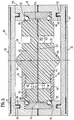
- Figures 1-4 show a double-sided magnetic compass of the simplest type with a mirror-symmetrical structure.
- the magnetic compass 1 consists of the housing 2, the movable part 3 and the pointer arrangement 4 arranged on both sides.
- the housing 2 consists essentially of the annular side part 5 and the two transparent cover parts 6, in which the fixed scale 11 is embedded.
- the annular side part 5 has on its surfaces a groove 7, into each of which an annular rib 8 on the cover sides 6 fits, the cover sides being fastened in the side part by means of a suitable adhesive 9.
- the inner side 10 of the annular side part is concave and polished in order to ensure that the balls 23 roll on it smoothly.
- the fixed scale 11 is indicated, which works with the two pointers 14 and 15.
- the movable part 3 is constructed from two identical parts and contains a disk-shaped magnet housing 16, which has a conical surface Has elevation 17, the tip of which represents the center of the pointer arrangement and has two rectangular cutouts 18 in which the pointers 14 and 15 are embedded.
- the magnet housing 16 serves to hold a magnet 19, which consists of a rare earth-cobalt alloy, in particular a samarium-cobalt alloy, or is a metallic glass. However, another suitable magnetic substance can be used, which can either be cuboid or can have any other shape.
- the two pointers 14 and 15 each have a pin 20 which is embedded in a corresponding hole in the magnet housing.
- the end face 21 of the magnet housing is curved outwards and forms an intermediate space 22 with the inner surface 10.
- the curved surface 21 has a bevel 24 such that a V-shaped groove 24 is formed, which forms the other running surface of the spherical ring and holding the bullets.
- the disk-shaped magnet housing consists of two identical parts and furthermore has two recesses 25 for receiving a weight compensation cylinder 26, which can be made of brass, for example, see FIG. 2.
- a weight compensation cylinder 26 which can be made of brass, for example, see FIG. 2.
- FIG. 3 shows a section perpendicular to FIG. 2, two centering pins 27 can be seen, which are fastened in a corresponding bore 28 in the magnet housing.
- Suitable material for the magnet housing and the ring-shaped side part is, above all, a suitable, hard plastic that enables the required smooth running surfaces.
- the transparent cover sides are also conveniently made of plastic.
- FIG. 5 shows an embodiment variant for the double-sided magnetic compass, two cuts combined in one figure, analogous to FIGS. 2 and 3 of the first exemplary embodiment.
- the housing 29 of the magnetic compass 30 is also in this Design variant from an annular side part 31, two transparent cover sides 32 and the movable part 33 with the pointer arrangement 34.
- the entire magnetic compass body is also constructed symmetrically and the circumferential ribs 35 in the cover sides are fitted into corresponding grooves 36 in the side part 31 by means of adhesive and attached.
- the fixed scale 37 is also arranged on the transparent cover parts.
- the annular side part is also made in two parts and glued together.
- the movable part 33 is held by two spherical rings 38 and 39, the balls 40 here likewise being made of an amagnetic material.
- the balls are held on the outside by a double cage ring 41, which is embedded in the annular side part 31 and whose two inwardly facing edges 42 are arcuate, in such a way that the balls are freely movable but are held without play.
- the movable part 33 consists of two identical disc halves 43, on which the pointers 45 and 46 are arranged or let in, these pointers being able to be inserted into corresponding bores 48 by means of pins 47.
- the disc halves 43 and 44 of this movable part have a conical elevation 49 in their center and are connected to one another via centering pins 50 which are fitted into corresponding bores 51.
- the magnetic substance is not cuboid as in the previous embodiment variant, but as a flat one Magnetic disk 52, which can be produced, for example, by vapor deposition and subsequent alignment.
- This disk has corresponding openings 53 at the location of the centering pins 50.
- Such a magnetic disk can also be used in the first exemplary embodiment according to FIGS. 1 to 4.
- the outer edge 54 of the disc halves is convex and its surface is such that the balls 40 can roll on it effortlessly.
- the movable part presents itself as a relatively flat disc, it is possible to make it spherical, which also makes it possible to position it spatially, for example on the polar star.
- the second embodiment is also relatively easy to manufacture and assemble in order to produce a precise compass that can be read from both sides.
- FIGS. 6 and 7 show a simpler embodiment of a compass, the movable part of which is also mounted on a spherical ring.
- the compass 55 contains a housing 56 made of non-magnetic brass, which is closed at the top with a transparent cover 57. This cover, best vapor-deposited from below as in the other exemplary embodiments, has the fixed scale 12.
- Figure 6 in which the compass is shown in the top view, the cover glass with the scale is omitted.
- the housing 56 there is an insert 58 made of plastic, which has a polished, hemispherical running surface 59. This insert is pressed into the housing and glued and sealed with it.
- the movable part 60 consists of an annular part 61 in which the magnet 62 is fitted and a disc 68 thereon on which the Pointers 63 and 64 are arranged.
- the hands can either be embedded or glued on or simply colored in the mass. If necessary, the magnet housing also contains recesses to attach a balance weight.
- the disk has a conical elevation 65 on its surface, which defines the center point. The notch 66 is for alignment purposes.
- the movable part 60 rests on rings 67 arranged in the form of a ring, which on the one hand are made of an amagnetic material and on the other hand together give a weight which is greater than the rest of the compass body. This ensures that the balls or the moving part are always in the correct position.
- the dimensions of the magnet housing and the conical elevation with respect to the cover glass or the running surface must be dimensioned such that the balls always remain arranged in a ring and a ball cannot escape in any position.
Landscapes
- Engineering & Computer Science (AREA)
- Radar, Positioning & Navigation (AREA)
- Remote Sensing (AREA)
- Physics & Mathematics (AREA)
- General Physics & Mathematics (AREA)
- Lenses (AREA)
- Transmission And Conversion Of Sensor Element Output (AREA)
- Electrochromic Elements, Electrophoresis, Or Variable Reflection Or Absorption Elements (AREA)
- Soft Magnetic Materials (AREA)
- Toys (AREA)
Priority Applications (3)
| Application Number | Priority Date | Filing Date | Title |
|---|---|---|---|
| DE59006850T DE59006850D1 (de) | 1990-11-21 | 1990-11-21 | Magnetkompass. |
| EP90810899A EP0486742B1 (fr) | 1990-11-21 | 1990-11-21 | Boussole magnétique |
| AT90810899T ATE110164T1 (de) | 1990-11-21 | 1990-11-21 | Magnetkompass. |
Applications Claiming Priority (1)
| Application Number | Priority Date | Filing Date | Title |
|---|---|---|---|
| EP90810899A EP0486742B1 (fr) | 1990-11-21 | 1990-11-21 | Boussole magnétique |
Publications (2)
| Publication Number | Publication Date |
|---|---|
| EP0486742A1 true EP0486742A1 (fr) | 1992-05-27 |
| EP0486742B1 EP0486742B1 (fr) | 1994-08-17 |
Family
ID=8205968
Family Applications (1)
| Application Number | Title | Priority Date | Filing Date |
|---|---|---|---|
| EP90810899A Expired - Lifetime EP0486742B1 (fr) | 1990-11-21 | 1990-11-21 | Boussole magnétique |
Country Status (3)
| Country | Link |
|---|---|
| EP (1) | EP0486742B1 (fr) |
| AT (1) | ATE110164T1 (fr) |
| DE (1) | DE59006850D1 (fr) |
Cited By (1)
| Publication number | Priority date | Publication date | Assignee | Title |
|---|---|---|---|---|
| CN104197905A (zh) * | 2014-09-15 | 2014-12-10 | 瑞安市顺风航仪有限公司 | 一种防气泡回流上室的磁罗经 |
Citations (2)
| Publication number | Priority date | Publication date | Assignee | Title |
|---|---|---|---|---|
| DE2028114A1 (de) * | 1970-06-08 | 1971-12-16 | Bartlett Compass Co Ltd | Magnetkompass |
| EP0181834A2 (fr) * | 1984-10-29 | 1986-05-21 | Patrick Stolz | Corps de boussole |
-
1990
- 1990-11-21 EP EP90810899A patent/EP0486742B1/fr not_active Expired - Lifetime
- 1990-11-21 DE DE59006850T patent/DE59006850D1/de not_active Expired - Fee Related
- 1990-11-21 AT AT90810899T patent/ATE110164T1/de not_active IP Right Cessation
Patent Citations (2)
| Publication number | Priority date | Publication date | Assignee | Title |
|---|---|---|---|---|
| DE2028114A1 (de) * | 1970-06-08 | 1971-12-16 | Bartlett Compass Co Ltd | Magnetkompass |
| EP0181834A2 (fr) * | 1984-10-29 | 1986-05-21 | Patrick Stolz | Corps de boussole |
Cited By (1)
| Publication number | Priority date | Publication date | Assignee | Title |
|---|---|---|---|---|
| CN104197905A (zh) * | 2014-09-15 | 2014-12-10 | 瑞安市顺风航仪有限公司 | 一种防气泡回流上室的磁罗经 |
Also Published As
| Publication number | Publication date |
|---|---|
| EP0486742B1 (fr) | 1994-08-17 |
| DE59006850D1 (de) | 1994-09-22 |
| ATE110164T1 (de) | 1994-09-15 |
Similar Documents
| Publication | Publication Date | Title |
|---|---|---|
| EP0530178B1 (fr) | Fermoir magnetique | |
| EP0486742B1 (fr) | Boussole magnétique | |
| WO2007012939A1 (fr) | Boitier de blindage contre les champs magnetiques | |
| DE1797555U (de) | Gelenk. | |
| AT328760B (de) | Instrumentenzeiger mit einem lager | |
| DE1140422B (de) | Stossgesichertes, geraeuscharmes feinmechanisches Lager, insbesondere fuer Uhrwerke | |
| DE359903C (de) | Magnetische Daempfvorrichtung fuer schwingende Systeme, insbesondere fuer Messinstrumente | |
| AT223695B (de) | Stoßgesichertes Lager für Präzisionsapparate, Meßinstrumente u. dgl. | |
| DE2645068C2 (fr) | ||
| DE2747047C2 (de) | Manometer | |
| DE19529976C2 (de) | Neigungskompensierende Anzeigeeinrichtung für einen Kompaß sowie Kompaß mit einer neigungskompensierenden Anzeigeeinrichtung | |
| DE669348C (de) | Lager | |
| DE2620210B2 (de) | Anordnung zur elastischen Lagerung des Magnetkernes elektromagnetischer Schaltgeräte | |
| DE1400643U (fr) | ||
| DE1220224B (de) | Magnetisch, praktisch reibungslos gelagerte, bezueglich Drehung um ihre Laengsachsein indifferentem Gleichgewicht befindliche, horizontale oder annaehernd horizontale Systemachse | |
| DE959698C (de) | Axiale Lagerung einer Revolverhuelse auf einem Zapfen | |
| DE29501717U1 (de) | Flaches dauermagnetisches Haftsystem mit hoher Haftkraft und großer Streuweite an nur einer Fläche | |
| DD213766A1 (de) | Einrichtung zur schwingungsdaempfung bei empfindlichen geraeten, insbesondere mikroskopen | |
| DE1236838B (de) | Planetarium in Gestalt eines Hohlkoerpers mit Himmelskoerperdarstellungen an dessen Innenwand | |
| CH594228A5 (en) | Adjustable drawing instrument for forming and measuring circles - has plate with adjustable aperture iris mechanism to guide pencil | |
| DE1134862B (de) | Handbetaetigungsorgan mit Stellungsanzeige, insbesondere fuer Ventile | |
| AT223028B (de) | Aus zwei gekreuzten Prismen bestehender Indikator für Spiegelreflexkameras | |
| DE850691C (de) | Anschlusskupplung einer Luftleitung an den Scheibenzwischenraum des Fensters einer Flugzeugkabine | |
| DE2737047C2 (de) | Spannvorrichtung für scheibenförmige Folienspeicher | |
| DE2028114A1 (de) | Magnetkompass |
Legal Events
| Date | Code | Title | Description |
|---|---|---|---|
| PUAI | Public reference made under article 153(3) epc to a published international application that has entered the european phase |
Free format text: ORIGINAL CODE: 0009012 |
|
| AK | Designated contracting states |
Kind code of ref document: A1 Designated state(s): AT BE CH DE DK ES FR GB GR IT LI LU NL SE |
|
| RBV | Designated contracting states (corrected) |
Designated state(s): AT CH DE FR GB IT LI SE |
|
| 17P | Request for examination filed |
Effective date: 19921125 |
|
| 17Q | First examination report despatched |
Effective date: 19930817 |
|
| GRAA | (expected) grant |
Free format text: ORIGINAL CODE: 0009210 |
|
| ITF | It: translation for a ep patent filed | ||
| AK | Designated contracting states |
Kind code of ref document: B1 Designated state(s): AT CH DE FR GB IT LI SE |
|
| REF | Corresponds to: |
Ref document number: 110164 Country of ref document: AT Date of ref document: 19940915 Kind code of ref document: T |
|
| GBT | Gb: translation of ep patent filed (gb section 77(6)(a)/1977) |
Effective date: 19940817 |
|
| REF | Corresponds to: |
Ref document number: 59006850 Country of ref document: DE Date of ref document: 19940922 |
|
| PGFP | Annual fee paid to national office [announced via postgrant information from national office to epo] |
Ref country code: SE Payment date: 19941027 Year of fee payment: 5 |
|
| PGFP | Annual fee paid to national office [announced via postgrant information from national office to epo] |
Ref country code: AT Payment date: 19941130 Year of fee payment: 5 |
|
| ET | Fr: translation filed | ||
| EAL | Se: european patent in force in sweden |
Ref document number: 90810899.6 |
|
| PLBE | No opposition filed within time limit |
Free format text: ORIGINAL CODE: 0009261 |
|
| STAA | Information on the status of an ep patent application or granted ep patent |
Free format text: STATUS: NO OPPOSITION FILED WITHIN TIME LIMIT |
|
| 26N | No opposition filed | ||
| PG25 | Lapsed in a contracting state [announced via postgrant information from national office to epo] |
Ref country code: AT Effective date: 19951121 |
|
| PG25 | Lapsed in a contracting state [announced via postgrant information from national office to epo] |
Ref country code: SE Effective date: 19951122 |
|
| EUG | Se: european patent has lapsed |
Ref document number: 90810899.6 |
|
| PGFP | Annual fee paid to national office [announced via postgrant information from national office to epo] |
Ref country code: GB Payment date: 19961015 Year of fee payment: 7 |
|
| PGFP | Annual fee paid to national office [announced via postgrant information from national office to epo] |
Ref country code: FR Payment date: 19961025 Year of fee payment: 7 |
|
| PG25 | Lapsed in a contracting state [announced via postgrant information from national office to epo] |
Ref country code: GB Free format text: LAPSE BECAUSE OF NON-PAYMENT OF DUE FEES Effective date: 19971121 |
|
| PG25 | Lapsed in a contracting state [announced via postgrant information from national office to epo] |
Ref country code: FR Free format text: THE PATENT HAS BEEN ANNULLED BY A DECISION OF A NATIONAL AUTHORITY Effective date: 19971130 |
|
| GBPC | Gb: european patent ceased through non-payment of renewal fee |
Effective date: 19971121 |
|
| REG | Reference to a national code |
Ref country code: FR Ref legal event code: ST |
|
| PGFP | Annual fee paid to national office [announced via postgrant information from national office to epo] |
Ref country code: DE Payment date: 20001221 Year of fee payment: 11 |
|
| PG25 | Lapsed in a contracting state [announced via postgrant information from national office to epo] |
Ref country code: DE Free format text: LAPSE BECAUSE OF NON-PAYMENT OF DUE FEES Effective date: 20020702 |
|
| PGFP | Annual fee paid to national office [announced via postgrant information from national office to epo] |
Ref country code: CH Payment date: 20031124 Year of fee payment: 14 |
|
| PG25 | Lapsed in a contracting state [announced via postgrant information from national office to epo] |
Ref country code: LI Free format text: LAPSE BECAUSE OF NON-PAYMENT OF DUE FEES Effective date: 20041130 Ref country code: CH Free format text: LAPSE BECAUSE OF NON-PAYMENT OF DUE FEES Effective date: 20041130 |
|
| REG | Reference to a national code |
Ref country code: CH Ref legal event code: PL |
|
| PG25 | Lapsed in a contracting state [announced via postgrant information from national office to epo] |
Ref country code: IT Free format text: LAPSE BECAUSE OF NON-PAYMENT OF DUE FEES;WARNING: LAPSES OF ITALIAN PATENTS WITH EFFECTIVE DATE BEFORE 2007 MAY HAVE OCCURRED AT ANY TIME BEFORE 2007. THE CORRECT EFFECTIVE DATE MAY BE DIFFERENT FROM THE ONE RECORDED. Effective date: 20051121 |