EP0181872B1 - Filtre a frequence spatiale optique - Google Patents
Filtre a frequence spatiale optique Download PDFInfo
- Publication number
- EP0181872B1 EP0181872B1 EP85901790A EP85901790A EP0181872B1 EP 0181872 B1 EP0181872 B1 EP 0181872B1 EP 85901790 A EP85901790 A EP 85901790A EP 85901790 A EP85901790 A EP 85901790A EP 0181872 B1 EP0181872 B1 EP 0181872B1
- Authority
- EP
- European Patent Office
- Prior art keywords
- filter
- light
- color
- wave plate
- spatial frequency
- Prior art date
- Legal status (The legal status is an assumption and is not a legal conclusion. Google has not performed a legal analysis and makes no representation as to the accuracy of the status listed.)
- Expired
Links
Images



Classifications
-
- G—PHYSICS
- G02—OPTICS
- G02B—OPTICAL ELEMENTS, SYSTEMS OR APPARATUS
- G02B27/00—Optical systems or apparatus not provided for by any of the groups G02B1/00 - G02B26/00, G02B30/00
- G02B27/09—Beam shaping, e.g. changing the cross-sectional area, not otherwise provided for
- G02B27/0938—Using specific optical elements
- G02B27/0988—Diaphragms, spatial filters, masks for removing or filtering a part of the beam
-
- G—PHYSICS
- G02—OPTICS
- G02B—OPTICAL ELEMENTS, SYSTEMS OR APPARATUS
- G02B27/00—Optical systems or apparatus not provided for by any of the groups G02B1/00 - G02B26/00, G02B30/00
- G02B27/42—Diffraction optics, i.e. systems including a diffractive element being designed for providing a diffractive effect
- G02B27/46—Systems using spatial filters
-
- G—PHYSICS
- G02—OPTICS
- G02B—OPTICAL ELEMENTS, SYSTEMS OR APPARATUS
- G02B5/00—Optical elements other than lenses
- G02B5/30—Polarising elements
- G02B5/3083—Birefringent or phase retarding elements
-
- H—ELECTRICITY
- H04—ELECTRIC COMMUNICATION TECHNIQUE
- H04N—PICTORIAL COMMUNICATION, e.g. TELEVISION
- H04N23/00—Cameras or camera modules comprising electronic image sensors; Control thereof
- H04N23/10—Cameras or camera modules comprising electronic image sensors; Control thereof for generating image signals from different wavelengths
- H04N23/12—Cameras or camera modules comprising electronic image sensors; Control thereof for generating image signals from different wavelengths with one sensor only
Definitions
- This invention relates to optical spatial frequency filters particularly for use with discrete sampling image sensors.
- an image sensing system having an image sensor that samples the image at discrete sampling locations
- the production of the spurious spatial frequency components is called aliasing error.
- the effect occurs when the image includes spatial frequency components that are higher than one-half of the spatial sampling frequency of the sensor.
- Visual patterns produced by aliasing errors are often called Moire patterns.
- U.S. Patent No. 3 588 224 issued June 28, 1971 to D.H. Pritchard discloses an optical spatial frequency filter for use with a color TV camera tube having a striped color filter.
- the optical spatial frequency filter includes at least one pair of birefringent elements with a quarter wave plate positioned between them.
- the first birefringent element in the filter splits an incoming ray of light into two spaced apart rays linearly polarized perpendicular to each other.
- the quarter wave plate changes the polarization state of the light rays from linearly to circularly polarized by retarding one component of the light waves with respect to an orthogonal component by a quarter wavelength.
- the second birefringent element splits each of the two circularly polarized rays into two spaced apart rays to form an array of four spaced apart rays.
- each spot in the input image is split into four spaced apart spots on the image sensor.
- the image sensor is presented with four overlapping identical images, each image slightly displaced from the others.
- the resulting composite image presented to the image sensor appears as a slightly blurred version of the original image, having reduced spatial resolution.
- the spaced apart spots lie along a line, thereby limiting the spatial resolution in the direction of the line.
- the elements can be arranged relative to each other to cause the spaced apart spots to lie on the corners of a parallelogram, thereby limiting the spatial resolution in two orthogonal directions.
- Further birefringent elements and wave plates may be added to the filter to further modify its frequency response.
- the means for changing the polarization state of the light between the birefringent elements is an optically active element that directly rotates the polarization of the light, rather than retarding one component of it with respect to another.
- the spatial sampling frequency in one color is different from the spatial sampling frequency of another color.
- the spatial sampling frequency in green is twice the spatial sampling frequency in red or blue to account for the greater sensitivity of the human eye to green detail.
- the spatial frequency filters described above have been built to function in an achromatic fashion, i.e. the spatial frequency response of the filters is substantially the same for all colors.
- achromatic frequency response presents a dilemma for use with a color image sensor where the spatial sampling frequency is higher for one color than it is for another. If the frequency response of the filter is optimally chosen to reduce aliasing in the more highly sampled color (e.g. green), the spatial frequencies in the other less highly sampled colors (e.g. blue and red) will not be adequately limited, resulting in aliasing in these colors. On the other hand, if the frequency response of the spatial filter is optimized for the less highly sampled colors (e.g. red and blue), the spatial frequencies in the more highly sampled color (e.g. green), will be unduly limited, and the sharpness of an image reconstructed from the samples will be undesirably reduced.
- the frequency response of the filter is optimally chosen to reduce aliasing in the more highly sampled color (e.g. green)
- the spatial frequencies in the other less highly sampled colors e.g. blue and red
- the spatial frequencies in the more highly sampled color e.g. green
- the object is achieved according to the present invention by providing an optical spatial frequency filter as defined in claim 1 and having a color dependent spatial frequency response. This is accomplished by a wavelength dependent means for changing the polarization state of the light such that the polarization state of light of a first color is changed by a first amount, and the polarization state of light of a second color is changed by a second amount different from the first; the difference between said first amount and said second amount approximaties to , where k is an odd integer, such that the spatial frequency response of the spatial frequency filter is color dependent.
- the respective thicknesses of the elements, and their arrangement relative to each other are selected so that the spatial frequency response to the first color is related to the sampling frequency of the first color by the sensor, and the spatial frequency response to the second color is related to the sampling frequency of the second color.
- the spatial frequency response of the filter is color dependent so that aliasing effects can be reduced in a color image sensing system having an image sensor with different spatial sampling frequencies for different colors without sacrificing resolution in one or more of the colors.
- the color dependent optical spatial frequency filter is easily and inexpensively constructed. It is durable and is easily tailored for different frequency responses in one or two dimensions.
- the image sensing system shown in Fig. 1 includes a lens 10 for focusing an image onto a discrete sampling type color image sensor 12, such as a CCD image sensor having an overlying color filter array indicated by vertical stripes labeled GRGB to indicate green, red, green, and blue respectively, and a color dependent spatial frequency filter 14.
- a discrete sampling type color image sensor 12 such as a CCD image sensor having an overlying color filter array indicated by vertical stripes labeled GRGB to indicate green, red, green, and blue respectively, and a color dependent spatial frequency filter 14.
- the green filter elements (G) on the color image sensor 12 occur at twice the spatial frequency of the red (R) or blue (B) filter elements.
- a color dependent spatial frequency filter 14 limits the spatial frequencies in the green component of the input image to frequencies related to the frequency of green filter elements in the array of filter elements on the image sensor 12, and limits the spatial frequencies in the red and blue components of the input image to some lower frequency related to the frequencies of the red and blue filter elements on the image sensor 12.
- the color dependent spatial filter thereby reduces aliasing in each color in an image formed from the output signal S of the image sensor, without unnecessarily sacrificing resolution or sharpness in any of the colors of the image.
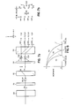
- Fig. 2 shows an exploded top view of the color dependent spatial frequency filter 14.
- the filter 14 comprises a first birefringent element 16, a wave plate 18, and a second birefringent element 20.
- the birefringent elements may be constructed from any of the doubly refracting mineral crystals such as clacite or quartz.
- the wave plate may be constructed from any of the naturally occurring doubly refracting crystals or man-made, oriented plastic materials used for constructing wave plates.
- the first birefringent element 16 having an optic axis 22 located parallel to the plane of the drawing as shown in Fig. 2, splits a ray of unpolarized white light W into an «ordinary» ray component (o) polarized in a direction perpendicular to the plane of the drawing, and indicated by a dot, and an «extraordinary» ray component (e) polarized in a direction in the plane of the drawing and perpendicular to the polarization of the «ordinary» ray, indicated by an arrow.
- the two rays emerge from the birefringent element in a direction parallel to and spaced apart from each other, and parallel to the input ray W.
- the wave plate 18 changes the polarization state of the red and blue components of the white light rays from linearly polarized to circularly polarized as indicated by the circular arrows labeled R, B, but does not affect the polarization state of the green component of the white light ray, as indicated by the arrow and dot labeled G. This result is achieved because the wave plate has the effect of a quarter wave plate in red and blue, and a full wave plate in green.
- the required thickness of such a wave plate can be calculated as explained below, and the wave plate is easily constructed.
- the second birefringent element 20, having an optic axis 24 deflects the light polarized in the plane of the drawing, into e rays indicated by the arrows, and passes the light polarized perpendicular to the plane of the drawing into o rays, as indicated by the dots.
- the circularly polarized light having equal components polarized in the plane of the drawing and perpendicular to the plane of the drawing, is equally split into the e and o rays.
- the light polarized linearly in the plane of the drawing is transmitted on the e ray while the light polarized perpendicular to the plane of the drawing is transmitted on the o ray.
- the circularly polarized red and blue components of the input light are equally split into the e and o rays, but the linearly polarized green component is transmitted totally on one or the other of the e or o rays.
- the four rays emerging from the second birefringent element 20 are colored.
- the top ray labeled eo to indicate that it derives from the e ray out of element 16 and the o ray out of element 20 is colored magenta because of the absence of green light.
- the bottom ray labeled oe is similarly colored.
- the two center rays labeled oo and ee respectively are colored green due to the predominance of green light in them.
- Fig. 2a shows the spatial cutoff frequency of the filter 14 when the four rays are spaced apart equally as shown in Fig. 2a, and the amount of red and blue light in all four spots is equal, the spatial cutoff frequency of the filter 14 will be twice as high for green as for blue or red.
- Fig. 2b shows the pattern of colored spots produced by the filter in response to a spot of unpolarized white light.
- the distances between the spots and the relative intensity of the spots determine the frequency responses of the filter 14.
- the distances are controlled by the respective thicknesses of the elements 16 and 20.
- the relative intensities are controlled by the arrangement of the elements, and the thickness or retardation of the wave plate.
- the frequency responses of the filter are selected in relation to the spacing of the colored filter elements on the image sensor.
- the spatial frequency responses are shown schematically in fig. 4.
- the line labeled 28 shows the spatial frequency response of the filter to green components of the input image.
- the green frequency response has a first zero at a spatial frequency equal to 1 2d G Where d G is the distance between the green colored spots.
- the line labeled 30 represents the spatial frequency response of the filter to red and blue components of the input image.
- the red and blue frequency response has a first zero at a spatial frequency of where d RB is the distance between the magenta colored spots.
- d RB 3d G
- the first zero of the frequency response for red and blue is
- the wave plate 18 between the two birefringent elements is a quarter wave plate for red and blue wavelengths of light, and a full wave plate for green wavelengths of light.
- a wave plate functions by retarding one component of a light ray with respect to another component, thereby changing the polarization state of the light ray.
- the retardation of a wave plate of thickness t is given by: where: ⁇ is the relative displacement between orthogonal components of the light ray in radians, ⁇ is the wavelength of the light, and (n e no) is the birefringence of the material.
- the birefringence is a weak function of wavelength ⁇ , called the dispersion of the birefringence, this effect is relatively small for most materials and can be safely ignored in first order calculations.
- the strong function of wavelength provided by the ⁇ in the denominator of the right hand side of equation (1) is what enables a wave plate to function as a full wave plate for green and a quarter wave plate for red and blue.
- the relative spot intensities can be calculated from the following equations: where: l xy are the relative intensities of the respective spots formed by the rays. Note that the total amount of energy in the pattern is defined to be 2.
- Fig. 11 shows some plots of spot intensity versus wavelength of light for the oo spot.
- the curve labeled 66 is for a first order full wave plate in green. As shown by curve 66 there is a gradual change in relative spot intensity throughout the visible spectrum.
- a color dependent spatial frequency filter of the type described above was constructed for a solid state color image sensor having a color filter stripe pattern like that shown in fig. 1, with the filter elements spaced on 12 ⁇ m centers.
- the birefringent crystals 16 and 20 were quartz slabs 2.30 mm and 4.35 mm thick respectively. These thicknesses were what were on hand in the laboratory at the time the experiment was conducted, more preferably thicknesses of 2,0 mm and 4,0 mm would be used.
- the optic axes of the quartz slabs were oriented about 45° to the surface of the slabs as shown in fig. 2a.
- the wave plate was a plastic wave plate of laminated cellulose acetate butyrate 0,76 mm (.030 inches) thick having first order full wave retardation at .53pm.
- the wave plate material was purchased in a sheet from the Polaroid Corporation under the product designation CAB Laminated Retarders.
- the wave plate can be manufactured by any of the standard methods of making a first order wave plate (see Chapter 10, page 10-112 of the Handbook of Optics, McGraw Hill (NY), 1978).
- the elements were oriented as shown in figs. 2a and 3, and were clamped together in a fixture and placed in the optical path of the image sensing system.
- the resulting filter produced four colored spots separated by approximately 13 V m, with 40 ⁇ m overall spacing between the eo and oe spots. Images produced by the image sensing system were observed to have substantially less aliasing in all three colors than images produced by the same system without the color dependent spatial filter. There was no noticeable loss of resolution in any color.
- the elements for manufacturing the filter can be produced inexpensively.
- the filters are simply constructed by stacking the elements in the proper orientation and securing them together with an index matching optical cement. The resulting structure is rugged and easily handled.
- birefringent element 20 is twice as thick as element 16, yielding equal separation between the four output rays.
- the relative spacing of the spots can be altered by varying the relative thicknesses of the birefringent elements 16 and 20. For example, if element 20 is made the same thickness as element 16, as shown in fig. 5a, the pattern of three spots shown in fig. 5b is produced. As just described, the red and blue intensity of the center spot would be twice that of the side spots in the pattern shown in fig. 5b.
- the arrangement of the elements can be modified so that the intensity of the red and blue light in the three spots is equal, as follows.
- the intensities of the spots can be calculated from the equations.
- 0 is the angle between the fast axis (the optic axis) of the wave plate and the direction of polarization of the e ray from the first birefringent element 16 as shown in fig. 3, and
- the intensity of colors of light in the spots can be varied. This is true in general for any of the embodiments disclosed herein. Because of the symmetry of the elements, pairs of spots will have equal intensity.
- the wave plate 18 has been described as a first order full wave plate for green. Higher order full wave plates may also be employed in the practice of the invention. As the order of the wave plate for green is increased however, the change in relative intensity versus wavelength for the spots increases.
- the rays produced by the color dependent spatial frequency filters have been arranged along a line. If one of the birefringent elements 16,20 is rotated 90° with respect to the other, the spots will be arranged in a rectangular pattern as shown in fig. 6b. If the birefringent elements 16 and 20 are of the same thickness, as shown in fig. 6a, the pattern will be square. With this arrangement, the spatial frequency response of the filter can be tailored to be different for different colors in different directions. This type of spatial filter is useful for example with an image sensor having different sampling frequencies in two orthoganal directions along the sensor. If this filter is rotated so that the oe and eo spots lie on a horizontal line, a diamond shaped pattern is produced.
- Green is blurred in the horizontal direction only, and red and blue are blurred in both the horizontal and vertical directions. It is noted that with the birefringent elements rotated 90" with respect to each other, at the second birefringent element 20, the o ray from the first birefringent element 16 becomes an e ray; and the e ray from the first element becomes an o ray with respect to the second birefringent element. As shown in fig. 6a, only the o ray from the first birefringent element 16 is shown. The e ray lies directly beneath the o ray and is not shown. Similarly, only the oo and oe rays emerging from birefringent element 20 are shown.
- the eo and ee rays lie respectively beneath the oo and oe rays and are not shown. If the angle between the birefringent elements is rotated to an angle other than a multiple of 90°, a parallelogram pattern is produced, and green light will be in all four spots.
- Fig. 7a shows an example of a two dimensional color dependent, spatial frequency filter for producing the pattern of colored spots shown in fig. 7b in response to a ray of unpolarized white light W.
- the spatial filter comprises three birefringent elements 50, 52 and 54, and two wave plates 56 and 58 sandwiched between the birefringent elements as shown.
- the first birefringent element 50 splits an unpolarized ray of white light into an o ray and an e ray. In the view shown in fig.
- the first birefringent element 50 is oriented so that the e ray lies directly beneath the o ray, and is not visible in the figure.
- the quarter wave plate 56 changes the polarization state of all the colors in both the e and o rays to circular polarization as indicated by the circular arrow labeled R, G, B.
- Birefringent element 52 splits each circularly polarized ray into an e ray and an o ray polarized perpendicular to each other as indicated by the dot and arrow in fig. 7a. Only the oe and oo rays are shown in fig. 7a, the ee and eo rays lying directly beneath the oe and oo rays respectively.
- Wave plate 58 is a full wave plate in green and a quarter wave plate in red and blue as described above, and changes the polarization state of the red and blue components of light to circular polarization, without affecting the polarization state of the green light.
- Birefringent element 54 splits each of the four rays into an e ray and an o ray. All the green light is shifted into the four inside spots ooo, oee, eoo, and eee. The red and blue light is equally shared in the eight spots shown in fig. 7b.
- Fig. 8 is a schematic diagram showing the frequency response of the filter shown in fig. 7a to the different colors of light in the different directions.
- the line labeled 60 shows that the frequency response of the spatial filter has a first zero in the x direction for green colors of light at a spatial frequency of 1/2d x(G) .
- the line labeled 62 shows that the frequency response of the spatial frequency filter has a first zero for all colors of light in the y direction at a spatial frequency of 1/2dy(RGB).
- the line labeled 64 shows that the frequency response of the spatial frequency filter has a first zero for red and blue color of light in the x direction at a spatial frequency corresponding to 1 /dX(G) + d x (RB).
- Table 2 below shows the relative spot intensities when ⁇ G is 4 ⁇ and 6n.
- Fig. 9b shows the spot pattern produced by the color dependent spatial frequency filter shown in fig. 9a.
- Fig. 10 is a schematic diagram showing the frequency response of the filter of fig. 9a to different colors.
- the line labeled 72 shows that the frequency response to green components of the image has a first zero at a spatial frequency of 1/2d G , where d G is shown in fig. 9b as the distance between the two center spots.
- the line labeled 74 in fig. 10 shows that the frequency response to red and blue components of the image has a first zero at 1 /2d RB , where d RB is shown in fig. 9b as the distance between the two outside spots.
- the wave plate placed between the birefringent elements has been described as a first-order or multiple-order full wave plate for green.
- Fig. 12a shows an exploded top view of a color dependent spatial frequency filter which uses a half wave plate in green.
- the wave plate 74 is a half wave plate for green and a quarter wave plate for red and blue.
- the wave plate 74 rotates the plane of polarization by 90° so that the o-ray from the first birefringent element 76 becomes an e-ray in the second element 78 and vice versa.
- red and blue light the wave plate 74 turns the input linear polarization into circular polarizations, causing four output spots to be produced by the second birefringent element 78.
- the output pattern produced by this filter (shown in fig. 12b), is the same as that produced by the filter shown in fig. 2a.
- the second birefringent element has been rotated by 180° from the earlier situation (note position of optic axis 80).
- the center two spots in the pattern are formed by the oe and eo rays as opposed to the oo and ee rays in fig. 2b.
- the spatial frequency response of this filter is the same as that shown in fig. 4.
- Equations (6) and (7) are valid for calculating the spot intensities for a linear array of spots produced by this filter.
- Electro-optic materials include KDP (potassium dihydrogen phosphate) and PLZT (lead zirconate titanate). With such materials, the spatial frequency response of the color dependent spatial frequency filter can be changed by changing the voltage across the electro-optic material.
- a color dependent optical spatial frequency filter has been described.
- the spatial frequency filter is particularly useful for limiting input spatial frequencies to color image sensors having different sampling frequencies in different colors to reduce aliasing in one color without reducing resolution in another color.
- the color dependent spatial frequency filter has the further advantages of being inexpensive and easy to manufacture.
- the filter is useful for example to improve the performance of image sensing apparatus such as television cameras, electronic still and movie cameras, or film video players having color image sensors with different sampling frequencies for different colors.
Landscapes
- Physics & Mathematics (AREA)
- General Physics & Mathematics (AREA)
- Optics & Photonics (AREA)
- Engineering & Computer Science (AREA)
- Multimedia (AREA)
- Signal Processing (AREA)
- Color Television Image Signal Generators (AREA)
- Polarising Elements (AREA)
- Optical Filters (AREA)
Abstract
Claims (5)
Applications Claiming Priority (2)
| Application Number | Priority Date | Filing Date | Title |
|---|---|---|---|
| US06/597,290 US4575193A (en) | 1984-04-06 | 1984-04-06 | Optical spatial frequency filter |
| US597290 | 1984-04-06 |
Publications (2)
| Publication Number | Publication Date |
|---|---|
| EP0181872A1 EP0181872A1 (fr) | 1986-05-28 |
| EP0181872B1 true EP0181872B1 (fr) | 1989-03-01 |
Family
ID=24390890
Family Applications (1)
| Application Number | Title | Priority Date | Filing Date |
|---|---|---|---|
| EP85901790A Expired EP0181872B1 (fr) | 1984-04-06 | 1985-03-21 | Filtre a frequence spatiale optique |
Country Status (6)
| Country | Link |
|---|---|
| US (1) | US4575193A (fr) |
| EP (1) | EP0181872B1 (fr) |
| JP (1) | JPS61501798A (fr) |
| DE (1) | DE3568499D1 (fr) |
| SG (1) | SG38789G (fr) |
| WO (1) | WO1985004730A1 (fr) |
Families Citing this family (75)
| Publication number | Priority date | Publication date | Assignee | Title |
|---|---|---|---|---|
| JPH0620316B2 (ja) * | 1982-05-17 | 1994-03-16 | 株式会社日立製作所 | 撮像光学系 |
| JP2593429B2 (ja) * | 1983-10-03 | 1997-03-26 | オリンパス光学工業株式会社 | 内視鏡 |
| JPH0772769B2 (ja) * | 1984-09-26 | 1995-08-02 | ソニー株式会社 | 固体撮像装置 |
| JP2556831B2 (ja) * | 1985-05-11 | 1996-11-27 | オリンパス光学工業株式会社 | 光学的ロ−パスフイルタ−及びこれを用いた撮像装置 |
| DE3686358T2 (de) * | 1985-05-27 | 1993-02-25 | Sony Corp | Optischer tiefpassfilter fuer eine festkoerper-farbkamera. |
| US4626919A (en) * | 1985-06-24 | 1986-12-02 | Hughes Aircraft Company | Apparatus for de-emphasizing low spatial frequencies in optical imaging systems |
| US4882619A (en) * | 1986-04-07 | 1989-11-21 | Olympus Optical Co., Ltd. | High resolution image pickup system with color dispersion means |
| US4786964A (en) * | 1987-02-02 | 1988-11-22 | Polaroid Corporation | Electronic color imaging apparatus with prismatic color filter periodically interposed in front of an array of primary color filters |
| US5237446A (en) * | 1987-04-30 | 1993-08-17 | Olympus Optical Co., Ltd. | Optical low-pass filter |
| JPS63291026A (ja) * | 1987-05-25 | 1988-11-28 | Olympus Optical Co Ltd | 結像光学系 |
| GB8713043D0 (en) * | 1987-06-03 | 1987-07-08 | British Telecomm | Optical switch |
| US5013140A (en) * | 1987-09-11 | 1991-05-07 | British Telecommunications Public Limited Company | Optical space switch |
| JP2826328B2 (ja) * | 1988-11-18 | 1998-11-18 | オリンパス光学工業株式会社 | 撮像装置 |
| US5477381A (en) * | 1989-02-02 | 1995-12-19 | Canon Kabushiki Kaisha | Image sensing apparatus having an optical low-pass filter |
| JP2615248B2 (ja) * | 1989-07-10 | 1997-05-28 | 富士写真フイルム株式会社 | 光学フイルタ |
| US5270825A (en) * | 1989-10-12 | 1993-12-14 | Olympus Optical Co., Ltd. | Imaging optical system having a moire elimination effect |
| US5157526A (en) * | 1990-07-06 | 1992-10-20 | Hitachi, Ltd. | Unabsorbing type polarizer, method for manufacturing the same, polarized light source using the same, and apparatus for liquid crystal display using the same |
| US5309239A (en) * | 1991-07-11 | 1994-05-03 | U.S. Philips Corporation | Image pick-up device |
| US5864428A (en) * | 1992-01-13 | 1999-01-26 | Hesline; Raymond | Polarizing device |
| JPH06169415A (ja) * | 1992-11-30 | 1994-06-14 | Olympus Optical Co Ltd | 撮像装置 |
| JP3224181B2 (ja) * | 1993-11-09 | 2001-10-29 | 富士通株式会社 | 光ディスクからのデータ再生システム |
| JP3592383B2 (ja) * | 1994-10-18 | 2004-11-24 | 呉羽化学工業株式会社 | 高分子製光学的ローパスフィルター、その複合体およびその製造方法並びに複合光学フィルター |
| US5570178A (en) * | 1994-12-09 | 1996-10-29 | Santa Barbara Research Center | Scanning imaging system having reduced detected signal aliasing in cross scan direction |
| US20020118457A1 (en) * | 2000-12-22 | 2002-08-29 | Dowski Edward Raymond | Wavefront coded imaging systems |
| US7218448B1 (en) * | 1997-03-17 | 2007-05-15 | The Regents Of The University Of Colorado | Extended depth of field optical systems |
| US20020195548A1 (en) * | 2001-06-06 | 2002-12-26 | Dowski Edward Raymond | Wavefront coding interference contrast imaging systems |
| US6911638B2 (en) | 1995-02-03 | 2005-06-28 | The Regents Of The University Of Colorado, A Body Corporate | Wavefront coding zoom lens imaging systems |
| US6252638B1 (en) | 1995-05-23 | 2001-06-26 | Colorlink, Inc. | Color controllable illumination device, indicator lights, transmissive windows and color filters employing retarder stacks |
| US6882384B1 (en) * | 1995-05-23 | 2005-04-19 | Colorlink, Inc. | Color filters and sequencers using color selective light modulators |
| US5999240A (en) * | 1995-05-23 | 1999-12-07 | Colorlink, Inc. | Optical retarder stack pair for transforming input light into polarization states having saturated color spectra |
| US5751384A (en) * | 1995-05-23 | 1998-05-12 | The Board Of Regents Of The University Of Colorado | Color polarizers for polarizing an additive color spectrum along a first axis and it's compliment along a second axis |
| US5822021A (en) * | 1996-05-14 | 1998-10-13 | Colorlink, Inc. | Color shutter liquid crystal display system |
| US6707516B1 (en) | 1995-05-23 | 2004-03-16 | Colorlink, Inc. | Single-panel field-sequential color display systems |
| US6183091B1 (en) * | 1995-04-07 | 2001-02-06 | Colorlink, Inc. | Color imaging systems and methods |
| US5929946A (en) * | 1995-05-23 | 1999-07-27 | Colorlink, Inc. | Retarder stack for preconditioning light for a modulator having modulation and isotropic states of polarization |
| US6417892B1 (en) | 1995-05-23 | 2002-07-09 | Colorlink, Inc. | Color filters, sequencers and displays using color selective light modulators |
| US6049367A (en) * | 1995-05-23 | 2000-04-11 | Colorlink, Inc. | Polarization manipulating device modulator with retarder stack which preconditions light for modulation and isotropic states |
| US6273571B1 (en) | 1995-05-23 | 2001-08-14 | Colorlink, Inc. | Display architectures using an electronically controlled optical retarder stack |
| US6654061B2 (en) * | 1995-06-14 | 2003-11-25 | Canon Kabushiki Kaisha | Automatic focus adjusting apparatus and method utilized by an image sensing apparatus |
| JP3660402B2 (ja) * | 1995-08-23 | 2005-06-15 | 富士通株式会社 | 光フィルタ |
| JP3883601B2 (ja) * | 1996-03-27 | 2007-02-21 | 富士通株式会社 | 光イコライザ |
| US6115155A (en) | 1996-10-29 | 2000-09-05 | Chorum Technologies Inc. | System for dealing with faults in an optical link |
| US6545783B1 (en) | 1996-10-29 | 2003-04-08 | Chorum Technologies Lp | Optical wavelength add/drop multiplexer |
| US6847786B2 (en) | 1996-10-29 | 2005-01-25 | Ec-Optics Technology, Inc. | Compact wavelength filter using optical birefringence and reflective elements |
| US6243200B1 (en) | 2000-03-02 | 2001-06-05 | Chorum Technologies, Inc. | Optical wavelength router based on polarization interferometer |
| US6163393A (en) | 1996-10-29 | 2000-12-19 | Chorum Technologies Inc. | Method and apparatus for wavelength multipexing/demultiplexing |
| US6937283B1 (en) * | 1996-12-03 | 2005-08-30 | Eastman Kodak Company | Anti-aliasing low-pass blur filter for reducing artifacts in imaging apparatus |
| JP3422913B2 (ja) * | 1997-09-19 | 2003-07-07 | アンリツ株式会社 | 光サンプリング波形測定装置 |
| US6021005A (en) * | 1998-01-09 | 2000-02-01 | University Technology Corporation | Anti-aliasing apparatus and methods for optical imaging |
| US6327085B1 (en) | 1998-03-31 | 2001-12-04 | Nikon Corporation | Optical filter and optical device provided with this optical filter |
| US6026203A (en) * | 1998-07-30 | 2000-02-15 | Hewlett-Packard Company | Polarization mixer based on walk-off crystals, half-wave plates and TEC fibers |
| US6519060B1 (en) | 1999-06-04 | 2003-02-11 | Chorum Technologies Lp | Synchronous optical network in frequency domain |
| US7116370B1 (en) | 2000-03-31 | 2006-10-03 | Sharp Laboratories Of Ameria, Inc. | Image processing system optical shifting mechanism |
| US6711311B2 (en) * | 2000-04-20 | 2004-03-23 | Jds Uniphase Inc. | Polarization beam splitter or combiner |
| US6536898B1 (en) * | 2000-09-15 | 2003-03-25 | The Regents Of The University Of Colorado | Extended depth of field optics for human vision |
| US6873733B2 (en) | 2001-01-19 | 2005-03-29 | The Regents Of The University Of Colorado | Combined wavefront coding and amplitude contrast imaging systems |
| US7173662B1 (en) * | 2001-04-30 | 2007-02-06 | Massachusetts Institute Of Technology | Foveating imaging system and method employing a spatial light modulator to selectively modulate an input image |
| US6515786B1 (en) | 2001-08-03 | 2003-02-04 | Chorum Technologies Lp | Bandwidth variable wavelength router and method of operation |
| US6842297B2 (en) | 2001-08-31 | 2005-01-11 | Cdm Optics, Inc. | Wavefront coding optics |
| US6667826B1 (en) * | 2002-03-01 | 2003-12-23 | The United States Of America As Represented By The Administrator Of The National Aeronautics And Space Administration | Chromatic modulator for high resolution CCD or APS devices |
| GB0208869D0 (en) * | 2002-04-18 | 2002-05-29 | Qinetiq Ltd | Imaging spectrometer |
| JP4533088B2 (ja) * | 2004-11-01 | 2010-08-25 | キヤノン株式会社 | 光学フィルタ及びそれを有する撮像装置 |
| US20060170797A1 (en) * | 2005-02-02 | 2006-08-03 | Biernath Rolf W | Article having a birefringent surface for use as a blur filter |
| US20060170808A1 (en) * | 2005-02-02 | 2006-08-03 | Biernath Rolf W | Article having a birefringent surface for use as a blur filter |
| JP2006243277A (ja) * | 2005-03-02 | 2006-09-14 | Fujinon Corp | 色分離光学系装置 |
| WO2008020449A2 (fr) * | 2006-08-16 | 2008-02-21 | Xceed Imaging Ltd. | Procédé et système pour imagerie avec zoom |
| US9347832B2 (en) * | 2008-05-15 | 2016-05-24 | Bodkin Design And Engineering Llc | Optical systems and methods employing a polarimetric optical filter |
| JP6108774B2 (ja) * | 2012-11-08 | 2017-04-05 | キヤノン株式会社 | レーザ装置およびそれを用いた光音響装置 |
| US10705799B2 (en) | 2015-03-04 | 2020-07-07 | Carol Y. Scarlett | Transmission of information through the use of quantum-optical effects within a multi-layered birefringent structure |
| US10007044B2 (en) * | 2015-06-24 | 2018-06-26 | Florida A&M University | Optical system for precision control of an electric field within the focus of a laser beam |
| US10178381B2 (en) | 2015-07-14 | 2019-01-08 | Microsoft Technology Licensing, Llc | Depth-spatial frequency-response assessment |
| US11269193B2 (en) * | 2017-11-27 | 2022-03-08 | Liqxtal Technology Inc. | Optical sensing device and structured light projector |
| CN108051947B (zh) * | 2018-01-09 | 2024-04-12 | 河北工业大学 | 一种色域拓宽装置 |
| EP3811148A4 (fr) * | 2018-05-14 | 2022-01-19 | Scarlett, Carol, Y. | Génération de nombres aléatoires grâce à l'utilisation d'effets d'optique quantique dans une structure biréfringente multicouche |
| DE112019006721T5 (de) * | 2019-03-19 | 2021-10-28 | Murata Manufacturing Co., Ltd. | Optische vorrichtung |
Family Cites Families (10)
| Publication number | Priority date | Publication date | Assignee | Title |
|---|---|---|---|---|
| US3438692A (en) * | 1965-03-08 | 1969-04-15 | Bell Telephone Labor Inc | Birefringent device for forming multiple images |
| US3531180A (en) * | 1967-10-26 | 1970-09-29 | Ibm | Dispersion compensated display system |
| US3588224A (en) * | 1969-06-03 | 1971-06-28 | Rca Corp | Adjustable bandwidth optical filter |
| JPS5445152A (en) * | 1977-09-17 | 1979-04-10 | Victor Co Of Japan Ltd | Optical comb type filter |
| JPS55105221A (en) * | 1979-02-05 | 1980-08-12 | Victor Co Of Japan Ltd | Optical comb type filter |
| JPS57119318A (en) * | 1981-01-16 | 1982-07-24 | Minolta Camera Co Ltd | Filter having special effect |
| JPS5888984A (ja) * | 1981-11-24 | 1983-05-27 | Toshiba Corp | カラ−撮像装置 |
| JPS58100802A (ja) * | 1981-12-11 | 1983-06-15 | Hitachi Ltd | 固体撮像装置 |
| JPH0620316B2 (ja) * | 1982-05-17 | 1994-03-16 | 株式会社日立製作所 | 撮像光学系 |
| JPS592017A (ja) * | 1982-06-29 | 1984-01-07 | Fujitsu Ltd | 光アイソレ−タ |
-
1984
- 1984-04-06 US US06/597,290 patent/US4575193A/en not_active Expired - Lifetime
-
1985
- 1985-03-21 EP EP85901790A patent/EP0181872B1/fr not_active Expired
- 1985-03-21 JP JP60501299A patent/JPS61501798A/ja active Pending
- 1985-03-21 WO PCT/US1985/000463 patent/WO1985004730A1/fr not_active Ceased
- 1985-03-21 DE DE8585901790T patent/DE3568499D1/de not_active Expired
-
1989
- 1989-06-21 SG SG387/89A patent/SG38789G/en unknown
Also Published As
| Publication number | Publication date |
|---|---|
| SG38789G (en) | 1989-11-17 |
| JPS61501798A (ja) | 1986-08-21 |
| DE3568499D1 (en) | 1989-04-06 |
| EP0181872A1 (fr) | 1986-05-28 |
| WO1985004730A1 (fr) | 1985-10-24 |
| US4575193A (en) | 1986-03-11 |
Similar Documents
| Publication | Publication Date | Title |
|---|---|---|
| US4575193A (en) | Optical spatial frequency filter | |
| US5347644A (en) | Three-dimensional image display device and systems and methods for implementation thereof | |
| US4127322A (en) | High brightness full color image light valve projection system | |
| US5237446A (en) | Optical low-pass filter | |
| US4719507A (en) | Stereoscopic imaging system with passive viewing apparatus | |
| US4772104A (en) | Achromatic tuner for birefringent optical filter | |
| US4726663A (en) | Switchable color filter with enhanced transmissivity | |
| KR100880761B1 (ko) | 편광 빔 스플리터를 지닌 이미지 투영 시스템 | |
| KR100795253B1 (ko) | 편광 광선 분할기를 갖는 이미지 영상 시스템 | |
| US4605956A (en) | Single-chip electronic color camera with color-dependent birefringent optical spatial frequency filter and red and blue signal interpolating circuit | |
| US4221464A (en) | Hybrid Brewster's angle wire grid infrared polarizer | |
| DE69123916T2 (de) | Dreidimensionale Vollfarben-Flachbildanzeige | |
| US6243198B1 (en) | High efficiency electromagnetic beam projector and systems and method for implementation thereof | |
| US5198928A (en) | Light weight binocular helmet visor display | |
| US5322998A (en) | Conical blur filter for reducing artifacts in imaging apparatus | |
| EP0454409A1 (fr) | Filtre optique passe-bas utilisant un réseau de phase sélectif en longueur d'onde | |
| KR20050037470A (ko) | 편광 광선 분할기를 갖는 이미지 프로젝션 시스템 | |
| EP0100178B1 (fr) | Elément de polarisation | |
| EP0584769B1 (fr) | Filtre passe-bas optique à deux dimensions | |
| US5684293A (en) | Anti-aliasing low-pass blur filter for reducing artifacts in imaging apparatus | |
| US6937283B1 (en) | Anti-aliasing low-pass blur filter for reducing artifacts in imaging apparatus | |
| EP0459554A1 (fr) | Dispositif d'affichage à cristal liquide | |
| JP2009503608A (ja) | デジタル的に切り替え可能なバンドパスフィルタ | |
| US4407566A (en) | Optical filter | |
| WO1992021046A1 (fr) | Dispositif de dispersion de lumiere |
Legal Events
| Date | Code | Title | Description |
|---|---|---|---|
| PUAI | Public reference made under article 153(3) epc to a published international application that has entered the european phase |
Free format text: ORIGINAL CODE: 0009012 |
|
| 17P | Request for examination filed |
Effective date: 19860325 |
|
| AK | Designated contracting states |
Kind code of ref document: A1 Designated state(s): DE FR GB NL |
|
| 17Q | First examination report despatched |
Effective date: 19870630 |
|
| GRAA | (expected) grant |
Free format text: ORIGINAL CODE: 0009210 |
|
| AK | Designated contracting states |
Kind code of ref document: B1 Designated state(s): DE FR GB NL |
|
| REF | Corresponds to: |
Ref document number: 3568499 Country of ref document: DE Date of ref document: 19890406 |
|
| ET | Fr: translation filed | ||
| PLBE | No opposition filed within time limit |
Free format text: ORIGINAL CODE: 0009261 |
|
| STAA | Information on the status of an ep patent application or granted ep patent |
Free format text: STATUS: NO OPPOSITION FILED WITHIN TIME LIMIT |
|
| 26N | No opposition filed | ||
| PGFP | Annual fee paid to national office [announced via postgrant information from national office to epo] |
Ref country code: GB Payment date: 19930219 Year of fee payment: 9 |
|
| PGFP | Annual fee paid to national office [announced via postgrant information from national office to epo] |
Ref country code: FR Payment date: 19930315 Year of fee payment: 9 |
|
| PGFP | Annual fee paid to national office [announced via postgrant information from national office to epo] |
Ref country code: NL Payment date: 19930331 Year of fee payment: 9 |
|
| PGFP | Annual fee paid to national office [announced via postgrant information from national office to epo] |
Ref country code: DE Payment date: 19930401 Year of fee payment: 9 |
|
| PG25 | Lapsed in a contracting state [announced via postgrant information from national office to epo] |
Ref country code: GB Effective date: 19940321 |
|
| PG25 | Lapsed in a contracting state [announced via postgrant information from national office to epo] |
Ref country code: NL Effective date: 19941001 |
|
| GBPC | Gb: european patent ceased through non-payment of renewal fee |
Effective date: 19940321 |
|
| NLV4 | Nl: lapsed or anulled due to non-payment of the annual fee | ||
| PG25 | Lapsed in a contracting state [announced via postgrant information from national office to epo] |
Ref country code: FR Effective date: 19941130 |
|
| PG25 | Lapsed in a contracting state [announced via postgrant information from national office to epo] |
Ref country code: DE Effective date: 19941201 |
|
| REG | Reference to a national code |
Ref country code: FR Ref legal event code: ST |