EP0181950A1 - Axiallager - Google Patents
Axiallager Download PDFInfo
- Publication number
- EP0181950A1 EP0181950A1 EP84113830A EP84113830A EP0181950A1 EP 0181950 A1 EP0181950 A1 EP 0181950A1 EP 84113830 A EP84113830 A EP 84113830A EP 84113830 A EP84113830 A EP 84113830A EP 0181950 A1 EP0181950 A1 EP 0181950A1
- Authority
- EP
- European Patent Office
- Prior art keywords
- spiral
- bearing
- thrust bearing
- spiral element
- thrust
- Prior art date
- Legal status (The legal status is an assumption and is not a legal conclusion. Google has not performed a legal analysis and makes no representation as to the accuracy of the status listed.)
- Withdrawn
Links
- 239000000919 ceramic Substances 0.000 claims description 9
- 239000000463 material Substances 0.000 claims description 8
- 238000012360 testing method Methods 0.000 description 14
- 239000007788 liquid Substances 0.000 description 13
- 239000012530 fluid Substances 0.000 description 9
- 238000005461 lubrication Methods 0.000 description 7
- DNIAPMSPPWPWGF-UHFFFAOYSA-N Propylene glycol Chemical compound CC(O)CO DNIAPMSPPWPWGF-UHFFFAOYSA-N 0.000 description 6
- 239000002184 metal Substances 0.000 description 4
- 229910052751 metal Inorganic materials 0.000 description 4
- 229910001018 Cast iron Inorganic materials 0.000 description 3
- 230000001050 lubricating effect Effects 0.000 description 3
- 230000002093 peripheral effect Effects 0.000 description 3
- HBMJWWWQQXIZIP-UHFFFAOYSA-N silicon carbide Chemical compound [Si+]#[C-] HBMJWWWQQXIZIP-UHFFFAOYSA-N 0.000 description 3
- XLYOFNOQVPJJNP-UHFFFAOYSA-N water Substances O XLYOFNOQVPJJNP-UHFFFAOYSA-N 0.000 description 3
- 229910052581 Si3N4 Inorganic materials 0.000 description 2
- 238000005299 abrasion Methods 0.000 description 2
- PNEYBMLMFCGWSK-UHFFFAOYSA-N aluminium oxide Inorganic materials [O-2].[O-2].[O-2].[Al+3].[Al+3] PNEYBMLMFCGWSK-UHFFFAOYSA-N 0.000 description 2
- 230000015572 biosynthetic process Effects 0.000 description 2
- 238000010276 construction Methods 0.000 description 2
- 238000001816 cooling Methods 0.000 description 2
- 230000006866 deterioration Effects 0.000 description 2
- 230000000694 effects Effects 0.000 description 2
- 238000000034 method Methods 0.000 description 2
- 238000007789 sealing Methods 0.000 description 2
- 229910010271 silicon carbide Inorganic materials 0.000 description 2
- HQVNEWCFYHHQES-UHFFFAOYSA-N silicon nitride Chemical compound N12[Si]34N5[Si]62N3[Si]51N64 HQVNEWCFYHHQES-UHFFFAOYSA-N 0.000 description 2
- 229910000906 Bronze Inorganic materials 0.000 description 1
- OKTJSMMVPCPJKN-UHFFFAOYSA-N Carbon Chemical compound [C] OKTJSMMVPCPJKN-UHFFFAOYSA-N 0.000 description 1
- 238000005422 blasting Methods 0.000 description 1
- 239000010974 bronze Substances 0.000 description 1
- 229910052799 carbon Inorganic materials 0.000 description 1
- KUNSUQLRTQLHQQ-UHFFFAOYSA-N copper tin Chemical compound [Cu].[Sn] KUNSUQLRTQLHQQ-UHFFFAOYSA-N 0.000 description 1
- 238000005260 corrosion Methods 0.000 description 1
- 238000004519 manufacturing process Methods 0.000 description 1
- 229910001220 stainless steel Inorganic materials 0.000 description 1
- 239000010935 stainless steel Substances 0.000 description 1
- 238000004227 thermal cracking Methods 0.000 description 1
Images


Classifications
-
- F—MECHANICAL ENGINEERING; LIGHTING; HEATING; WEAPONS; BLASTING
- F16—ENGINEERING ELEMENTS AND UNITS; GENERAL MEASURES FOR PRODUCING AND MAINTAINING EFFECTIVE FUNCTIONING OF MACHINES OR INSTALLATIONS; THERMAL INSULATION IN GENERAL
- F16C—SHAFTS; FLEXIBLE SHAFTS; ELEMENTS OR CRANKSHAFT MECHANISMS; ROTARY BODIES OTHER THAN GEARING ELEMENTS; BEARINGS
- F16C33/00—Parts of bearings; Special methods for making bearings or parts thereof
- F16C33/02—Parts of sliding-contact bearings
- F16C33/04—Brasses; Bushes; Linings
- F16C33/06—Sliding surface mainly made of metal
- F16C33/10—Construction relative to lubrication
- F16C33/1025—Construction relative to lubrication with liquid, e.g. oil, as lubricant
- F16C33/106—Details of distribution or circulation inside the bearings, e.g. details of the bearing surfaces to affect flow or pressure of the liquid
- F16C33/107—Grooves for generating pressure
-
- F—MECHANICAL ENGINEERING; LIGHTING; HEATING; WEAPONS; BLASTING
- F16—ENGINEERING ELEMENTS AND UNITS; GENERAL MEASURES FOR PRODUCING AND MAINTAINING EFFECTIVE FUNCTIONING OF MACHINES OR INSTALLATIONS; THERMAL INSULATION IN GENERAL
- F16C—SHAFTS; FLEXIBLE SHAFTS; ELEMENTS OR CRANKSHAFT MECHANISMS; ROTARY BODIES OTHER THAN GEARING ELEMENTS; BEARINGS
- F16C17/00—Sliding-contact bearings for exclusively rotary movement
- F16C17/04—Sliding-contact bearings for exclusively rotary movement for axial load only
- F16C17/045—Sliding-contact bearings for exclusively rotary movement for axial load only with grooves in the bearing surface to generate hydrodynamic pressure, e.g. spiral groove thrust bearings
-
- F—MECHANICAL ENGINEERING; LIGHTING; HEATING; WEAPONS; BLASTING
- F16—ENGINEERING ELEMENTS AND UNITS; GENERAL MEASURES FOR PRODUCING AND MAINTAINING EFFECTIVE FUNCTIONING OF MACHINES OR INSTALLATIONS; THERMAL INSULATION IN GENERAL
- F16C—SHAFTS; FLEXIBLE SHAFTS; ELEMENTS OR CRANKSHAFT MECHANISMS; ROTARY BODIES OTHER THAN GEARING ELEMENTS; BEARINGS
- F16C17/00—Sliding-contact bearings for exclusively rotary movement
- F16C17/12—Sliding-contact bearings for exclusively rotary movement characterised by features not related to the direction of the load
- F16C17/18—Sliding-contact bearings for exclusively rotary movement characterised by features not related to the direction of the load with floating brasses or brushing, rotatable at a reduced speed
Definitions
- the present invention relates to a thrust bearing, and more particularly to the thrust bearing used in a fluid wherein a fluid dynamic pressure is created between the elements of the bearing upon relative rotation thereof so that lubrication of the bearing is effected by the liquid under the dynamic pressure.
- a thrust bearing of a type noted above is usually employed in a submersible pump or a submersible motor, etc.
- One type of such thrust bearing utilizing dynamic pressure in liquid is known as a thrust bearing comprising a spiral element.
- a thrust bearing comprising a spiral element.
- spiral element is disclosed in Japanese Patent Publication No. 12121/66 and U.S. Patent Application Serial No. 627,731 filed on July 3, 1984 assigned to the same assignee of this application.
- the thrust bearing having such spiral element as above is required to be rotated in one direction only to produce the dynamic pressure between the spiral element and an opposing element which are caused to make relative rotation.
- a tilting pad type metal bearing e.g. a tilting pad type metal bearing
- metal bearing is rather easily abraded compared to the thrust bearing using a spiral element or is subjected to troubles caused by foreign materials entrained onto the bearing surfaces, is associated with relative large mechanical loss consuming large power and needs a lubricating medium of relatively high viscosity.
- conventional metal bearing is not suitable for equipment adapted to handle liquid of high temperature. Therefore, it has been desired to have a thrust bearing which may dissolve the drawbacks noted above.
- a disc element having a spiral groove pattern on each of its respective opposite surfaces is employed between flat elements opposing each other and is adapted to make relative rotation therebetween, one of the flat elements being coupled to a shaft for rotation with a thrust force.
- the spiral groove pattern on each of the opposite surfaces is formed such that the pattern generates a fluid dynamic pressure on the surface thereof when the flat elements are caused to make relative rotation within liquid with the disc element interposed therebetween.
- the disc element having spiral groove patterns on both surfaces is referred to as a spiral element.
- the spiral groove pattern is arranged to direct liquid from the peripheral portion to the central portion of the spiral element upon relative rotation caused between the spiral element and the opposing flat surface of the flat element.
- the spiral element according to the present invention is provided with the spiral groove pattern on opposite surfaces thereof, it is able to generate fluid pressure whenever the shaft is rotated in either the normal or the opposite direction.
- the spiral element is made of hard material and preferably sintered ceramics.
- a conventional tilting-pad type bearing is illustrated in cross section.
- An upper bearing support 2' is firmly secured to the bottom end of a rotatable shaft l' and a disc 3' is secured to the support 2'.
- a pad 8' opposing the disc 3' is disposed on a lower support 7' so as not to be rotatable relative to the support 7'.
- the lower support 7' is supported on a spherical surface 5' of a stationary shaft 4' so as to be prevented by a pin 6' from being rotated.
- FIG. 2 there is schematically shown in cross section a thrust bearing as one embodiment according to the present invention.
- An upper support 2 is secured to a rotatable shaft 1 so as to be rotated therewith.
- An upper flat element 12 of the thrust bearing is secured to the upper support 2.
- a lower support 7 is supported on a stationary shaft 4 through a spherical surface 5 and a lower flat element 13 is firmly received on the support 7.
- the lower support is prevented from rotation by a pin 6.
- the flat surfaces of the flat elements 12 and 13 are arranged to be opposed to each other with a predetermined gap therebetween. In this gap, a spiral element 10 is disposed so that the bearing elements 10, 12 and 13 are disposed within a bearing chamber 14 filled with a lubricating medium or liquid.
- the spiral element 10 is provided with a spiral groove pattern on each of the opposite surfaces thereof, the patterns on the opposite surfaces being formed so as to be opposite to each other with respect to the spiral direction.
- the spiral pattern will be explained referring to Fig. 3.
- a plurality of pins 15 are arranged around the spiral element 10 so as to prevent the spiral element from being radially displaced.
- a plan view of the spiral element 10 is illustrated in Fig. 3.
- the black portions in this drawing correspond to the recessed portions forming the grooves 11 and the central recessed area 16.
- the pattern on the opposite surface is formed in a reverse fashion to that shown in Fig. 3.
- the direction of the spiral grooves 11 is arranged to direct liquid from the peripheral portion toward the central portion 16, when the shaft 1 is driven in the normal direction with disposing the bearing in the liquid, to produce a dynamic fluid pressure between the opposing surfaces of the flat element 12 and the spiral element 10.
- the pattern on the opposite surface of the element 10 shown in Fig. 3 is formed in the reverse direction to that shown so that, when the shaft 1 is driven in the opposite direction, the fluid dynamic pressure is produced between the opposing surfaces of the spiral element 10 and the flat element 13.
- the spiral groove patterns on the opposite surfaces may be seen as similarly directed spiral patterns when viewed from one side.
- the elements 10, 12 and 13 are made of hard materials. It is particularly preferable to make the spiral element 10 from sintered ceramics such as silicon carbide (SiC), silicon nitride (Si 3 N 4 ) etc.
- the flat elements 12 and 13 are preferably made of alumina ceramics (A1 2 0 3 ), sintered hard metal, bronze containing lead and cast iron, etc.
- the ceramics are superior in anti-corrosion properties, they are difficult to be worked such as having grooves formed thereon.
- the depth of the grooves on the spiral element was formed to be preferably within the range between 3 ⁇ m and 50 ⁇ m. Formation of such grooves on the surface of ceramics has been difficult.
- the process for such formation using shot-blasting has been made available by such a method as is disclosed in U.S. Patent Application Serial No. 627,731 and description thereof is incorporated herein.
- the upper and lower supports 2 and 7 may be made unitarily with the upper and lower elements 12 and 13, respectively.
- the lubrication medium is forcibly directed from the peripheral portion to the central portion of the spiral element 10 through grooves 11 and produce a dynamic fluid pressure between the elements 10 and 12 for forming a liquid film of such thickness as is necessary to suspend the thrust load.
- the opposite surface area of the spiral element no dynamic pressure is produced due to the backward direction of the spiral grooves formed thereon and there is tendency to discharge liquid outwardly through the grooves which state causes a suctioning effect between the elements 10 and 13 whereby the spiral element 10 becomes adhered to the flat element 13.
- Fig. 4 schematically illustrates the testing equipment.
- the thrust bearing under test is represented by the reference 21 comprising elements 21A and 21B.
- 21A corresponds to the element 3' and 21B corresponds to the pad element 8' in Fig. 1, respectively.
- 21A corresponds to the flat element 12 and 21B corresponds to the flat element 13 in Fig. 2, respectively and the spiral element is interposed between 21A and 21B.
- a rotary shaft 23 supports the rotary element 21A and is driven by a variable speed motor 24 through a belt 31 trained around pulleys 25.
- the motor 24 may rotate at a speed of between 10 r.p.m.
- a torque meter 26 is mounted on the shaft 23.
- the element 21B is disposed on a non-rotatable shaft 27.
- a hydraulic cylinder 28 (capable of applying maximum thrust of 10,000 kg.f) is coupled to the shaft 27 so as to impose a test load on the hearing to be tested.
- the hydraulic cylinder 28 is operated by a hydraulic pump 29.
- a load cell 30 is disposed between the cylinder 28 and the shaft 27 to measure the thrust load.
- Spiral element was the same as that in Test I except for the flat elements which were made of cast iron and lubrication medium which was 75% propylene glycol.
- Lubrication medium was 75% propylene glycol.
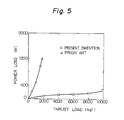
- Test II is graphically shown in Fig. 5 wherein the relationship between the power loss v.s. thrust load is plotted.
- the conventional thrust bearing seized at a thrust of 1800 kg.f and the power loss was as large as 1200 W at this point.
- the thrust bearing according to the present invention there was no seizure at the high load of 10,000 kg.f and the power loss was measured as being as small as 280 W at this point.
- the intermediate spiral element was kept stationary relative to the flat element where the fluid dynamic pressure is not produced. This is because the friction coefficient is 0.003 between the spiral element and the flat element in the case where there is a dynamic fluid pressure produced between the elements, whereas it reaches approximately 0.3 where the dynamic pressure is not produced. Therefore, there is a difference of over 100 times in the required torque in terms of the ratio between the opposite surfaces of the spiral element and this large difference substantially keeps the spiral element stationary relative to the flat element at one side of the spiral element.
Landscapes
- Engineering & Computer Science (AREA)
- General Engineering & Computer Science (AREA)
- Mechanical Engineering (AREA)
- Chemical & Material Sciences (AREA)
- Oil, Petroleum & Natural Gas (AREA)
- Physics & Mathematics (AREA)
- Fluid Mechanics (AREA)
- Sliding-Contact Bearings (AREA)
Priority Applications (1)
| Application Number | Priority Date | Filing Date | Title |
|---|---|---|---|
| EP84113830A EP0181950A1 (de) | 1984-11-15 | 1984-11-15 | Axiallager |
Applications Claiming Priority (1)
| Application Number | Priority Date | Filing Date | Title |
|---|---|---|---|
| EP84113830A EP0181950A1 (de) | 1984-11-15 | 1984-11-15 | Axiallager |
Publications (1)
| Publication Number | Publication Date |
|---|---|
| EP0181950A1 true EP0181950A1 (de) | 1986-05-28 |
Family
ID=8192286
Family Applications (1)
| Application Number | Title | Priority Date | Filing Date |
|---|---|---|---|
| EP84113830A Withdrawn EP0181950A1 (de) | 1984-11-15 | 1984-11-15 | Axiallager |
Country Status (1)
| Country | Link |
|---|---|
| EP (1) | EP0181950A1 (de) |
Cited By (2)
| Publication number | Priority date | Publication date | Assignee | Title |
|---|---|---|---|---|
| DE3809703A1 (de) * | 1988-03-23 | 1989-10-05 | Schaeffler Waelzlager Kg | Axialgleitlager |
| EP0412509A3 (en) * | 1989-08-11 | 1992-02-26 | Ebara Corporation | Bearing structure |
Citations (3)
| Publication number | Priority date | Publication date | Assignee | Title |
|---|---|---|---|---|
| US3439962A (en) * | 1966-06-21 | 1969-04-22 | Skf Ind Inc | Reversible sliding bearings of spiral or helical groove type |
| US3883314A (en) * | 1970-06-29 | 1975-05-13 | Omega Brandt & Freres Sa Louis | Self-lubrication bearing member |
| FR2381199A1 (fr) * | 1977-02-22 | 1978-09-15 | Philips Nv | Systeme pour monter au moins une bielle sur un maneton d'un vilebrequin |
-
1984
- 1984-11-15 EP EP84113830A patent/EP0181950A1/de not_active Withdrawn
Patent Citations (3)
| Publication number | Priority date | Publication date | Assignee | Title |
|---|---|---|---|---|
| US3439962A (en) * | 1966-06-21 | 1969-04-22 | Skf Ind Inc | Reversible sliding bearings of spiral or helical groove type |
| US3883314A (en) * | 1970-06-29 | 1975-05-13 | Omega Brandt & Freres Sa Louis | Self-lubrication bearing member |
| FR2381199A1 (fr) * | 1977-02-22 | 1978-09-15 | Philips Nv | Systeme pour monter au moins une bielle sur un maneton d'un vilebrequin |
Cited By (3)
| Publication number | Priority date | Publication date | Assignee | Title |
|---|---|---|---|---|
| DE3809703A1 (de) * | 1988-03-23 | 1989-10-05 | Schaeffler Waelzlager Kg | Axialgleitlager |
| EP0412509A3 (en) * | 1989-08-11 | 1992-02-26 | Ebara Corporation | Bearing structure |
| US5142173A (en) * | 1989-08-11 | 1992-08-25 | Ebara Corporation | Bearing structure |
Similar Documents
| Publication | Publication Date | Title |
|---|---|---|
| US4575264A (en) | Thrust bearing | |
| EP0209808B1 (de) | Axiallager | |
| CN112513402B (zh) | 多晶金刚石向心轴承 | |
| JP4495402B2 (ja) | 摺動部品 | |
| US4335888A (en) | Mechanical seal | |
| EP3341623A1 (de) | Kippsegmentlageranordnungen und lagervorrichtungen sowie verfahren zur verwendung davon | |
| JPH11287329A (ja) | 摺動材 | |
| EP0181950A1 (de) | Axiallager | |
| Smith | Material selection criteria for water lubrication | |
| KR200145217Y1 (ko) | 공기 동압 베어링 | |
| US20060119049A1 (en) | Slip-ring seal arrangement | |
| CA1239183A (en) | Thrust bearing | |
| US4618270A (en) | Hydrostatic bearing structure | |
| EP0872672B1 (de) | Dichtungsanordnung zur Montage um einer Pumpenwelle | |
| GB2296298A (en) | Sliding bearing | |
| CN104169597A (zh) | 滑动止推轴承 | |
| KR920002158B1 (ko) | 드러스트 베어링 | |
| JPH11351242A (ja) | 低粘度液潤滑軸受 | |
| EP0900959A2 (de) | Gleitringdichtung | |
| JPS6029012B2 (ja) | セラミック摺動装置 | |
| RU2213283C1 (ru) | Уплотнение торцевое | |
| RU160032U1 (ru) | Опорный узел | |
| JPS6199721A (ja) | 水中スラスト軸受 | |
| JPH0424572B2 (de) | ||
| RU2116535C1 (ru) | Торцевое уплотнение вращающегося вала |
Legal Events
| Date | Code | Title | Description |
|---|---|---|---|
| PUAI | Public reference made under article 153(3) epc to a published international application that has entered the european phase |
Free format text: ORIGINAL CODE: 0009012 |
|
| AK | Designated contracting states |
Kind code of ref document: A1 Designated state(s): DE FR GB IT NL SE |
|
| 17P | Request for examination filed |
Effective date: 19860707 |
|
| 17Q | First examination report despatched |
Effective date: 19870527 |
|
| STAA | Information on the status of an ep patent application or granted ep patent |
Free format text: STATUS: THE APPLICATION IS DEEMED TO BE WITHDRAWN |
|
| 18D | Application deemed to be withdrawn |
Effective date: 19880208 |
|
| RIN1 | Information on inventor provided before grant (corrected) |
Inventor name: MIZOBUCHI, SHOTARO Inventor name: SASAKI, KATSUMI Inventor name: KIMURA, YOSHIKAZU Inventor name: KASAHARA, KAZUYUKI |