EP0182037A1 - Couteau rotatif pour la granulation de boudins en plastique - Google Patents
Couteau rotatif pour la granulation de boudins en plastique Download PDFInfo
- Publication number
- EP0182037A1 EP0182037A1 EP85111998A EP85111998A EP0182037A1 EP 0182037 A1 EP0182037 A1 EP 0182037A1 EP 85111998 A EP85111998 A EP 85111998A EP 85111998 A EP85111998 A EP 85111998A EP 0182037 A1 EP0182037 A1 EP 0182037A1
- Authority
- EP
- European Patent Office
- Prior art keywords
- clamping
- groove
- cutting
- tool body
- longitudinal
- Prior art date
- Legal status (The legal status is an assumption and is not a legal conclusion. Google has not performed a legal analysis and makes no representation as to the accuracy of the status listed.)
- Granted
Links
Images


Classifications
-
- B—PERFORMING OPERATIONS; TRANSPORTING
- B26—HAND CUTTING TOOLS; CUTTING; SEVERING
- B26D—CUTTING; DETAILS COMMON TO MACHINES FOR PERFORATING, PUNCHING, CUTTING-OUT, STAMPING-OUT OR SEVERING
- B26D7/00—Details of apparatus for cutting, cutting-out, stamping-out, punching, perforating, or severing by means other than cutting
- B26D7/26—Means for mounting or adjusting the cutting member; Means for adjusting the stroke of the cutting member
- B26D7/2614—Means for mounting the cutting member
-
- B—PERFORMING OPERATIONS; TRANSPORTING
- B02—CRUSHING, PULVERISING, OR DISINTEGRATING; PREPARATORY TREATMENT OF GRAIN FOR MILLING
- B02C—CRUSHING, PULVERISING, OR DISINTEGRATING IN GENERAL; MILLING GRAIN
- B02C18/00—Disintegrating by knives or other cutting or tearing members which chop material into fragments
- B02C18/06—Disintegrating by knives or other cutting or tearing members which chop material into fragments with rotating knives
- B02C18/16—Details
- B02C18/18—Knives; Mountings thereof
- B02C18/186—Axially elongated knives
-
- B—PERFORMING OPERATIONS; TRANSPORTING
- B29—WORKING OF PLASTICS; WORKING OF SUBSTANCES IN A PLASTIC STATE IN GENERAL
- B29B—PREPARATION OR PRETREATMENT OF THE MATERIAL TO BE SHAPED; MAKING GRANULES OR PREFORMS; RECOVERY OF PLASTICS OR OTHER CONSTITUENTS OF WASTE MATERIAL CONTAINING PLASTICS
- B29B9/00—Making granules
- B29B9/02—Making granules by dividing preformed material
- B29B9/06—Making granules by dividing preformed material in the form of filamentary material, e.g. combined with extrusion
Definitions
- the invention relates to a rotary cutting tool, in particular for strand granulation of plastics, with a cylindrical tool body, which has a number of longitudinally evenly distributed longitudinal grooves, each of which contains a releasably inserted, elongated cutting element which extends essentially over the axial length of the tool body , which is clamped in position against the groove wall by means of clamping bodies inserted into the respective longitudinal groove with play, which are clamped against the cutting element and against wall parts of the longitudinal groove, with the clamping bodies being assigned at least one adjustable clamping device which gives the clamping bodies their pretension.
- a cutting tool has already become known, in which plate-like or strip-shaped cutting elements are used in corresponding longitudinal grooves of the cylindrical tool body, each of which by means of an at least partially made of plastic or elastomeric clamping body with the wall the respective longitudinal groove can be clamped.
- the longitudinal groove In order to prevent the plastic or elastomeric material, which is under high pressure, from flowing away and the tensioning effect which is triggered, the longitudinal groove must be sealed against the inserted cutting element, which requires a close tolerance of the cutting elements and the longitudinal grooves.
- the cutting elements in the form of ring-shaped knives are fastened to a knife shaft in that each of the knives has an annular groove which is open towards the knife shaft , into the serving as a clamp body Balls are inserted, which are arranged side by side in a row.
- a clamping device designed as a clamping screw, acting approximately radially, causes the balls to be braced against one another as well as against the knife shaft and the wall of the annular groove via a pressure ball.
- the ring-shaped knives are only non-positively and not positively coupled to the knife shaft, which is also not necessary because of the ring shape of the knives.
- the strip-shaped cutting elements are also each clamped against a side wall of the longitudinal grooves of the tool body which are limited in cross-section and are U-shaped and have parallel flanks.
- the clamping bodies used for this purpose are designed in the form of cylindrical rollers, the diameter of which is smaller than the groove width and which are arranged in each longitudinal groove in the form of a row with mutually offset axes.
- the longitudinal grooves are closed in the area of the end faces of the tool body by block-like abutments, which serve as tensioning devices, which allow the clamping bodies of such a row to be braced both against one another and against the groove side walls, one of which has the cutting element clamped in this way in a frictionally locking manner wearing.
- the individual rollers In order to avoid that the cylindrical rollers are thrown outwards under centrifugal force when the tension decreases, the individual rollers must be designed with circumferential retaining grooves which engage with their own retaining strips. This means a considerable effort. That being said, the strip-like cutting elements are le diglich frictionally supported and designed such that when replacing a cutting element, the newly inserted cutting element must be adjusted precisely to the flight circle of the other cutting elements, which experience has shown that this is not readily possible without special devices.
- the object of the invention is therefore to provide a concentric cutting tool of the type mentioned above with individually interchangeable cutting elements, which is characterized by a straightforward construction by an exactly correct, tightly tolerated mounting of the cutting elements on the tool body, the cutting elements being properly clamped.
- the cutting tool according to the invention is characterized in that the longitudinal grooves in the area of the groove opening are formed with mutually opposite clamping surfaces to be pointed towards one another, and the cutting elements in the foot region have correspondingly designed supporting surfaces assigned to the clamping surfaces, with which they are correctly positioned on the clamping surfaces are positively supported, and that the cutting elements are clamped by the clamping body essentially in the radial direction against the tool body.
- clamping and support surfaces provided / assigned to one another on the tool body in the region of the longitudinal grooves and on the cutting elements result in an exactly correct fixing of the cutting elements with respect to the tool body, which is independent of the clamping and does not require any adjustment work when inserting or changing the cutting elements.
- the cutting elements can simply be inserted laterally into the longitudinal grooves. After tightening the respective clamping device, they are clamped in the radial direction against the precisely dimensioned clamping surfaces of the tool body by the clamping elements, without their position being influenced by the clamping process. After releasing the respective clamping device, the cutting elements can simply be pulled out of the longitudinal grooves laterally and replaced by other cutting elements.
- the cutting elements and, if applicable, the tool body can be produced as investment castings, with the tool body then only having to be machined by means of the inner bore provided for placement on the shaft, the customary fitting bores in the end faces of the tool body and the clamping surfaces in the individual longitudinal grooves. Similarly, with the cutting elements, only the support surfaces and possibly the cutting edges require processing.
- the arrangement is such that the clamping bodies are balls, each inserted in a row with mutually offset centers in a longitudinal groove, and that each row of balls is supported on both sides in the longitudinal direction of the groove against abutments arranged on the tool body, at least of which one which has the tensioning device which gives the balls of this row their pretension.
- the cutting elements are tensioned evenly over their entire axial length. Any be Special measures for holding the metal balls in the longitudinal grooves are not necessary, since the longitudinal grooves are completely closed even in the circumferential direction by the cutting elements.
- the longitudinal groove width is expediently substantially the same or slightly larger than the ball diameter, so that the balls of a row with their centers lie approximately on a common radial plane containing the tool body axis of rotation, in which they alternately have different radial distances from the tool body axis of rotation.
- the balls of each row are held captive by themselves.
- the arrangement can also be made such that the balls of each row are held in the associated longitudinal groove by a cage.
- all the longitudinal grooves of the unequipped tool body can first be filled with balls and only then can the cutting elements be inserted.
- the clamping bodies are cylindrical clamping sleeves, which are slotted over part of their length and are formed in the region of their bore with internal wedge-shaped or conical clamping surfaces, which extend over a conical expanding surface into an internal thread supporting bore screwed clamping screw are supported, at least two clamping sleeves with clamping screws accessible from the end face of the tool body are inserted into each longitudinal groove.
- At least one spacer lying between the clamping sleeves can be arranged in each longitudinal groove.
- Both embodiments result in a completely smooth design of the tool body in the area between the cutting elements, which are free of depressions, recesses and the like. There are irregularities on which plastic material could adhere, which would lead to difficulties when changing colors.
- the clamping surfaces assigned to each other in pairs are each advantageously formed in a substantially V-shaped manner facing one another, it being possible for them to be formed by groove-like depressions in the side walls of the longitudinal grooves. These groove-like depressions can extend over the entire axial length of the tool body and open towards the end faces of the tool body, so that the cutting elements can be easily inserted above the abutments carrying the clamping devices when the clamping devices are released.
- the cutting elements advantageously have contact surfaces for the clamping elements which are opposite the support surfaces and which can expediently be formed by a groove which is approximately V-shaped in cross section. In this way it can be achieved that the forces exerted by the clamping elements in the radial direction on the cutting elements are evenly distributed over the two supporting surfaces of a cutting element, so that there is also a uniform support on the assigned clamping surfaces of the tool body.
- the longitudinal grooves in their bottom wall have contact surfaces adapted to the spherical shape, which can be formed, for example, by a V-shaped or partially circular depression.
- the longitudinal grooves can also be essentially dovetail-shaped in cross section.
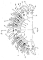
- FIG. 1 shows a rotary cutting tool according to the invention in a first embodiment, in a side view, partially cut open and in a detail
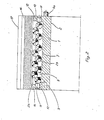
- FIG. 2 shows the cutting tool according to FIG. 1, cut along the line II-II in FIG. 1, in a side view and in FIG 3 a part of a row of balls of the arrangement according to FIG. 2 in the embodiment with an associated cage in a side view and on a different scale
- FIG. 4 a cutting roller composed of several cutting tools according to FIG.
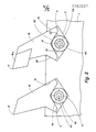
- FIG concentric cutting tool according to the invention in a second embodiment, in cross section and in detail and on a different scale, in a side view
- Figure 6 shows the cutting tool of Figure 5 in a longitudinal section similar to Figure 2 and in plan view.
- the rotary cutting tool shown in FIGS. 1, 2 and 5, 6 in two embodiments is used for pelletizing plastic material. It has one cylindrical tool body 1, which consists of steel and is formed with a coaxial inner bore 2, with which it can be rotatably attached to a drive shaft, not shown. On the face side, the tool body 1 carries axially parallel fitting bores 3 or fitting bolts 4 assigned to them, which allow the tool bodies to be assembled into a cutting roller in the manner shown in FIG. 4.
- the tool body 1 is provided with a number of longitudinal grooves 4 arranged uniformly distributed in the circumferential direction, each of which has two parallel side walls 5, 6 and a bottom wall 7 which is V-shaped in cross section.
- the longitudinal grooves extend at an indicated in Fig. 4 at 8 axis angle of 2 0 to 3 Q obliquely inclined to the respective tool body axis 3 radial plane containing.
- the longitudinal grooves 4 are closed by two abutments 10, which end at a certain distance from the peripheral surface of the tool body 1 and each of which carries a clamping device in the form of a clamping screw 11, which can be actuated from the tool body end face and is designed as a grub screw.
- the coaxial tensioning screws 11, which are aligned parallel to the respective longitudinal groove 4, are screwed into corresponding threaded bores of the abutment 10, the axes of which in the circumferential direction are centered on the assigned longitudinal groove.
- the abutment 10 can be formed in one piece on the tool body 1. For manufacturing reasons, however, it is easier to form the abutment 10 on end plates 13 which are coaxial on the face of the work Tool body 1 placed and screwed rigidly with this. The longitudinal grooves 4 can thus be milled out continuously in the tool body 1.
- each longitudinal groove 4 has, next to the straight parallel side walls 5, 6, two opposite, continuous dovetail groove-like depressions 14, which extend above the abutment 10 to the end faces of the tool body 1 or the end disks 13 and thus to open the front.
- each longitudinal groove 4 a strip-shaped cutting element 16 is inserted, the cutting edges 17 of which run on a common flight circle and which is formed in its foot region at 18 with two opposite V-shaped or wedge-shaped support surfaces 19, 20.
- the support surfaces 19, 20 have the same inclination as the associated clamping surfaces 15 of the tool body 1, so that when the cutting elements 16 are inserted into the longitudinal grooves 4, the cutting elements 16 with their supporting surfaces 19, 20 lie snugly against the clamping surfaces 15 and closely cooperate with them tolerated are held positively in their respective position, as it corresponds to the cutting edge geometry to be achieved.
- Each cutting element 16 is provided in the foot region 18 with a longitudinal groove 21 which is approximately V-shaped in cross section and which is delimited by two contact surfaces 22 opposite the support surfaces 19, 20.
- each longitudinal groove 4 clamping elements in the form of steel balls 23 are arranged, the diameter of which is slightly smaller than the longitudinal groove width given by the spacing of the flat side surfaces 5, 6, such that the balls 23 are movable in the longitudinal grooves 4 with some lateral play.
- the radial depth of the longitudinal grooves 4 is selected such that the balls 23 of each series in the associated longitudinal slot 4 with their center points approximately on a aemeinsamen the istkör p ermosachse 9 radial plane containing lie alternately have different radial center distances of the tool body axis of rotation 9 as this can be seen from Fig. 2. Every second ball 23 lies against the contact surfaces 22 of the cutting element 16 closing the longitudinal groove 4; it alternates with a ball 23, which is supported on the bottom wall 7 of the longitudinal groove 4. On the face side, the end balls 23 of each row of balls rest on the associated two clamping screws 11, whose axes are essentially aligned with the center of these balls.
- the row of balls is first filled into the respective longitudinal groove 4 through the groove opening, whereupon the associated clamping element 16 is inserted with its foot region 18 from the side until it assumes the position shown in FIGS. 1, 2. Then the clamping screws 11 are tightened, which cause the balls 23 of the row of balls, which are mutually supported via their spherical surfaces, alternately radially outwards and radially inwards against the contact surfaces 22 of the cutting element 16 or against the Bottom wall 7 of the tool body 1 are pressed. The cutting element 16 is thus clamped essentially in the radial direction, with its support surfaces 19, 20 being pressed against the clamping surfaces 15 of the tool body 1 and thus being fixed in the correct position.
- each longitudinal groove 4 is assigned two coaxial clamping screws 11.
- each longitudinal groove 4 is assigned two coaxial clamping screws 11.
- the balls 23 of each row of balls can be held in the associated longitudinal groove by a wire cage 25, as illustrated in FIG. 3.
- the mobility of the balls 23 is not impaired by the wire cage 25.
- the cutting elements 16 can be manufactured as extrusions or investment castings, so that any economical wear material can be used. Only the two support surfaces 19, 20, which act as clamping surfaces, of which one (19) is formed directly on the flat rear surface 26 of the clamping element 16 and the other (20) is provided on a foot 27 opposite the rear surface 26, require true-to-size machining will.
- the second embodiment of the rotary cutting tool shown in FIGS. 5, 6 essentially corresponds to the first embodiment, as described above with reference to FIGS. 1 to 4, except for the design of the clamping elements.
- the same parts of both embodiments are therefore provided with the same reference numerals, so that a further explanation is unnecessary.
- the strip-shaped cutting elements 16 inserted into the longitudinal grooves 4 are of the same design as in the first embodiment mentioned. They can either consist entirely of a suitable cutting material, for example stellite, or can carry inserted cutting bodies 16a made of hard metal (see FIG. 5) on which the cutting edges 17 are formed.
- Each of the cutting elements 16 is supported with its two opposite V-shaped or wedge-shaped support surfaces 19, 20 on the clamping surfaces 15 and, in cooperation with them, is held in the respective position in a form-fitting manner and with a close tolerance.
- two clamping elements in the form of cylindrical clamping sleeves 60 are inserted into each longitudinal groove 4 and are inserted into the respective longitudinal groove 4 from the two end faces of the tool body 1.
- an elongated spacer 61 is arranged in each longitudinal groove 4, which can consist, for example, of plastic material, the length of which is dimensioned such that the two clamping sleeves 60 are held at a mutual distance approximately corresponding to the axial length of the tool body 1.
- Each of the clamping sleeves 60 is provided in the manner of a so-called expansion dowel over part of its length with, for example, three evenly distributed longitudinal slots 62 which extend from the outer circumferential surface into the central threaded bore 63 of each clamping sleeve 60.
- a clamping screw 64 is screwed into the threaded bore 63 and has a key attachment 65 that is accessible from the adjacent end face of the tool body 1.
- each clamping screw 64 carries a conical spreading surface 66, with which it rests on wedge-shaped or conical clamping surfaces 67 arranged inside in the area of the threaded bore 63, as can be seen from FIG. 6.
- a cutting element 16 is inserted into the respective longitudinal groove 4 of the tool body 1, whereupon a spacer 61 and the two clamping sleeves 60 are inserted from the respective front side of the tool body.
- the clamping screws 64 are in the clamping sleeves 60 as far back rotates that the clamping sleeves 60 are not spread radially, so that the insertion of the clamping sleeves 60 is possible with play.
- This second embodiment of the cutting tool described above is therefore distinguished by a particularly simple construction of the clamping device for the cutting elements 16.
- the production of the tool body 1 is also simplified because the longitudinal grooves 4, which are dovetail-shaped in cross section, can be produced with little expenditure of time.
Landscapes
- Engineering & Computer Science (AREA)
- Mechanical Engineering (AREA)
- Life Sciences & Earth Sciences (AREA)
- Forests & Forestry (AREA)
- Food Science & Technology (AREA)
- Milling Processes (AREA)
- Processing And Handling Of Plastics And Other Materials For Molding In General (AREA)
Priority Applications (1)
| Application Number | Priority Date | Filing Date | Title |
|---|---|---|---|
| AT85111998T ATE45119T1 (de) | 1984-10-25 | 1985-09-21 | Rundlaufendes schneidwerkzeug, insbesondere zum stranggranulieren von kunststoffen. |
Applications Claiming Priority (2)
| Application Number | Priority Date | Filing Date | Title |
|---|---|---|---|
| DE3439029A DE3439029C2 (de) | 1984-10-25 | 1984-10-25 | Rundlaufendes Schneidwerkzeug, insbesondere zum Stranggranulieren von Kunststoffen |
| DE3439029 | 1984-10-25 |
Publications (2)
| Publication Number | Publication Date |
|---|---|
| EP0182037A1 true EP0182037A1 (fr) | 1986-05-28 |
| EP0182037B1 EP0182037B1 (fr) | 1989-08-02 |
Family
ID=6248703
Family Applications (1)
| Application Number | Title | Priority Date | Filing Date |
|---|---|---|---|
| EP85111998A Expired EP0182037B1 (fr) | 1984-10-25 | 1985-09-21 | Couteau rotatif pour la granulation de boudins en plastique |
Country Status (3)
| Country | Link |
|---|---|
| EP (1) | EP0182037B1 (fr) |
| AT (1) | ATE45119T1 (fr) |
| DE (2) | DE3439029C2 (fr) |
Cited By (8)
| Publication number | Priority date | Publication date | Assignee | Title |
|---|---|---|---|---|
| EP0344348A1 (fr) * | 1988-06-02 | 1989-12-06 | Hans Hench | Couteaux rotatifs pour la granulation des matériaux plastiques |
| EP0357549A1 (fr) * | 1988-09-02 | 1990-03-07 | Bidurit Hartmetall AG | Couteaux rotatifs |
| EP0377060A1 (fr) * | 1989-01-03 | 1990-07-11 | Hans Hench | Outil de coupe rotatif, en particulier pour la granulation de rubans de matière synthétique |
| US5042733A (en) * | 1990-08-06 | 1991-08-27 | Hans Hench | Rotary cutter, particularly for granulating plastic material |
| EP0491237A1 (fr) * | 1990-12-17 | 1992-06-24 | Michael Weinig Aktiengesellschaft | Tête porte-lames |
| EP0687535A4 (fr) * | 1993-03-02 | 1995-12-27 | ||
| WO2000032367A1 (fr) * | 1998-12-02 | 2000-06-08 | Rieter Automatik Gmbh | Appareil de granulation comportant un rotor coupant |
| US6776203B1 (en) * | 2003-03-28 | 2004-08-17 | Esse Emme Di Casadei Roberto & C. S.N.C. | Device for rapidly fixing blades onto the shafts of wood planers |
Families Citing this family (5)
| Publication number | Priority date | Publication date | Assignee | Title |
|---|---|---|---|---|
| DE3605363A1 (de) * | 1986-02-20 | 1987-08-27 | Waldemar Winkler Fa | Trennmesser fuer eine messerwalze |
| DE29504630U1 (de) * | 1995-03-17 | 1995-06-08 | Gämmerler, Hagen, 82057 Icking | Schneidmesser für Rotationsschneidanlagen für Papier |
| DE29616642U1 (de) * | 1996-08-13 | 1997-12-11 | Widia GmbH, 45145 Essen | Werkzeug mit einem platten- oder scheibenförmigen Werkzeughalter und mindestens einem Schneideinsatz |
| DE102007025292A1 (de) * | 2007-05-30 | 2008-12-04 | Karim Ould-Mimoun | Vorrichtung zum Herausschneiden verklebter Scheiben |
| DE102018100646A1 (de) * | 2018-01-12 | 2019-07-18 | Georg Thoma | Klemmvorrichtung und Klemmeinheit |
Citations (6)
| Publication number | Priority date | Publication date | Assignee | Title |
|---|---|---|---|---|
| FR355541A (fr) * | 1905-06-08 | 1905-11-06 | Wilhelm Wemhoener | Dispositif pour fixer les outils dans les mandrins porte-fraises et porte-outils |
| GB1063544A (en) * | 1964-07-31 | 1967-03-30 | Ferd Klingelnberg Soehne G M B | Securing of circular knives on smooth knife shafts |
| DE2215029A1 (de) * | 1971-03-27 | 1972-10-05 | Svenska Ind Tablerings Svetab | Fräser |
| DE2355290A1 (de) * | 1973-11-06 | 1975-05-07 | Hamilton Tool Co | Zylinder mit auswechselbarem messer |
| US3987525A (en) * | 1975-09-30 | 1976-10-26 | E.G. Larssons Hardmetall Ab | Rotary cutter |
| DE2829732A1 (de) * | 1978-07-06 | 1980-01-17 | Scheer & Cie C F | Schneidwerkzeug |
-
1984
- 1984-10-25 DE DE3439029A patent/DE3439029C2/de not_active Expired
-
1985
- 1985-09-21 EP EP85111998A patent/EP0182037B1/fr not_active Expired
- 1985-09-21 AT AT85111998T patent/ATE45119T1/de not_active IP Right Cessation
- 1985-09-21 DE DE8585111998T patent/DE3571952D1/de not_active Expired
Patent Citations (6)
| Publication number | Priority date | Publication date | Assignee | Title |
|---|---|---|---|---|
| FR355541A (fr) * | 1905-06-08 | 1905-11-06 | Wilhelm Wemhoener | Dispositif pour fixer les outils dans les mandrins porte-fraises et porte-outils |
| GB1063544A (en) * | 1964-07-31 | 1967-03-30 | Ferd Klingelnberg Soehne G M B | Securing of circular knives on smooth knife shafts |
| DE2215029A1 (de) * | 1971-03-27 | 1972-10-05 | Svenska Ind Tablerings Svetab | Fräser |
| DE2355290A1 (de) * | 1973-11-06 | 1975-05-07 | Hamilton Tool Co | Zylinder mit auswechselbarem messer |
| US3987525A (en) * | 1975-09-30 | 1976-10-26 | E.G. Larssons Hardmetall Ab | Rotary cutter |
| DE2829732A1 (de) * | 1978-07-06 | 1980-01-17 | Scheer & Cie C F | Schneidwerkzeug |
Cited By (12)
| Publication number | Priority date | Publication date | Assignee | Title |
|---|---|---|---|---|
| EP0344348A1 (fr) * | 1988-06-02 | 1989-12-06 | Hans Hench | Couteaux rotatifs pour la granulation des matériaux plastiques |
| EP0357549A1 (fr) * | 1988-09-02 | 1990-03-07 | Bidurit Hartmetall AG | Couteaux rotatifs |
| CH678027A5 (fr) * | 1988-09-02 | 1991-07-31 | Krupp Widia Schweiz Ag | |
| EP0377060A1 (fr) * | 1989-01-03 | 1990-07-11 | Hans Hench | Outil de coupe rotatif, en particulier pour la granulation de rubans de matière synthétique |
| US5042733A (en) * | 1990-08-06 | 1991-08-27 | Hans Hench | Rotary cutter, particularly for granulating plastic material |
| EP0491237A1 (fr) * | 1990-12-17 | 1992-06-24 | Michael Weinig Aktiengesellschaft | Tête porte-lames |
| US5337812A (en) * | 1990-12-17 | 1994-08-16 | Michael Weinig Aktiengesellschaft | Blade head for cutting blades |
| EP0687535A4 (fr) * | 1993-03-02 | 1995-12-27 | ||
| WO2000032367A1 (fr) * | 1998-12-02 | 2000-06-08 | Rieter Automatik Gmbh | Appareil de granulation comportant un rotor coupant |
| US6386469B1 (en) | 1998-12-02 | 2002-05-14 | Rieter Automatik Gmbh | Granulating device with a cutting rotor |
| DE19855617C2 (de) * | 1998-12-02 | 2003-07-17 | Rieter Automatik Gmbh | Granuliervorrichtung mit Schneidrotor |
| US6776203B1 (en) * | 2003-03-28 | 2004-08-17 | Esse Emme Di Casadei Roberto & C. S.N.C. | Device for rapidly fixing blades onto the shafts of wood planers |
Also Published As
| Publication number | Publication date |
|---|---|
| ATE45119T1 (de) | 1989-08-15 |
| EP0182037B1 (fr) | 1989-08-02 |
| DE3571952D1 (en) | 1989-09-07 |
| DE3439029C2 (de) | 1986-11-20 |
| DE3439029A1 (de) | 1986-05-07 |
Similar Documents
| Publication | Publication Date | Title |
|---|---|---|
| EP0722809B1 (fr) | Dispositif d'accouplement | |
| EP0182037B1 (fr) | Couteau rotatif pour la granulation de boudins en plastique | |
| EP0344348B1 (fr) | Couteaux rotatifs pour la granulation des matériaux plastiques | |
| EP0433925B1 (fr) | Dispositif de serrage hydraulique | |
| EP2603340B1 (fr) | Porte-outil | |
| DE3708034A1 (de) | Messerkopf | |
| EP0718080A1 (fr) | Lame de scie | |
| EP0096083B1 (fr) | Outil de coupe rotatif en particulier pour la granulation de rubans de matière synthétique | |
| DE2707842C3 (de) | Raspelwerkzeug für eine Schäl- und Raspelvorrichtung zum Abtragen von Reifenlaufflächen | |
| EP0357549A1 (fr) | Couteaux rotatifs | |
| DE2914500A1 (de) | Nabe, insbesondere fuer rotierendes werkzeug bzw. schleifkoerper | |
| EP1410864A1 (fr) | Outil ou fraise de filetage et méthode de sa fabrication | |
| DE3720203A1 (de) | Verfahren zur herstellung eines raeumwerkzeugs | |
| DE69108096T2 (de) | Riemenscheibe. | |
| EP0879663B1 (fr) | Outil de coupe avec serrage de plaquette simple | |
| DE3122574C1 (de) | Innenraeumwerkzeug | |
| EP0173862A2 (fr) | Appareil pour faire des cannelures dans des pièces, de préférence dans des pièces cylindriques | |
| DE3217242C2 (de) | Vorrichtung zum Schneiden einer unprofilierten Riemenhülse zur Herstellung eines endlosen Kraftübertragungsriemens | |
| EP0231812B1 (fr) | Rabot | |
| EP0266447A1 (fr) | Dispositif de coupe rotatif, en particulier pour un granulateur de matière plastique | |
| DE3311796A1 (de) | Vorrichtung zum durchtrennen von werkstuecken | |
| DE3536585C2 (fr) | ||
| DE3936883A1 (de) | Fraeskopf zur holzbearbeitung | |
| DE2300031C3 (de) | Zusammengesetzte Räumnadel zum Bearbeiten von Bohrungen | |
| DE2153414C3 (de) | Honwerkzeug |
Legal Events
| Date | Code | Title | Description |
|---|---|---|---|
| PUAI | Public reference made under article 153(3) epc to a published international application that has entered the european phase |
Free format text: ORIGINAL CODE: 0009012 |
|
| AK | Designated contracting states |
Kind code of ref document: A1 Designated state(s): AT BE CH DE FR GB IT LI LU NL SE |
|
| 17P | Request for examination filed |
Effective date: 19861115 |
|
| 17Q | First examination report despatched |
Effective date: 19880119 |
|
| GRAA | (expected) grant |
Free format text: ORIGINAL CODE: 0009210 |
|
| AK | Designated contracting states |
Kind code of ref document: B1 Designated state(s): AT BE CH DE FR GB IT LI LU NL SE |
|
| PG25 | Lapsed in a contracting state [announced via postgrant information from national office to epo] |
Ref country code: SE Effective date: 19890802 Ref country code: NL Effective date: 19890802 Ref country code: IT Free format text: LAPSE BECAUSE OF FAILURE TO SUBMIT A TRANSLATION OF THE DESCRIPTION OR TO PAY THE FEE WITHIN THE PRESCRIBED TIME-LIMIT;WARNING: LAPSES OF ITALIAN PATENTS WITH EFFECTIVE DATE BEFORE 2007 MAY HAVE OCCURRED AT ANY TIME BEFORE 2007. THE CORRECT EFFECTIVE DATE MAY BE DIFFERENT FROM THE ONE RECORDED. Effective date: 19890802 Ref country code: GB Effective date: 19890802 Ref country code: FR Free format text: THE PATENT HAS BEEN ANNULLED BY A DECISION OF A NATIONAL AUTHORITY Effective date: 19890802 Ref country code: BE Effective date: 19890802 |
|
| REF | Corresponds to: |
Ref document number: 45119 Country of ref document: AT Date of ref document: 19890815 Kind code of ref document: T |
|
| RAP2 | Party data changed (patent owner data changed or rights of a patent transferred) |
Owner name: FRITSCH, RUDOLF P. |
|
| REF | Corresponds to: |
Ref document number: 3571952 Country of ref document: DE Date of ref document: 19890907 |
|
| PG25 | Lapsed in a contracting state [announced via postgrant information from national office to epo] |
Ref country code: AT Effective date: 19890921 |
|
| RIN2 | Information on inventor provided after grant (corrected) |
Free format text: FRITSCH, RUDOLF P. * HENCH, HANS, DIPL.-ING. |
|
| PG25 | Lapsed in a contracting state [announced via postgrant information from national office to epo] |
Ref country code: LU Free format text: LAPSE BECAUSE OF NON-PAYMENT OF DUE FEES Effective date: 19890930 Ref country code: LI Effective date: 19890930 Ref country code: CH Effective date: 19890930 |
|
| EN | Fr: translation not filed | ||
| BECN | Be: change of holder's name |
Effective date: 19890802 |
|
| NLV1 | Nl: lapsed or annulled due to failure to fulfill the requirements of art. 29p and 29m of the patents act | ||
| PGFP | Annual fee paid to national office [announced via postgrant information from national office to epo] |
Ref country code: DE Payment date: 19900116 Year of fee payment: 5 |
|
| GBV | Gb: ep patent (uk) treated as always having been void in accordance with gb section 77(7)/1977 [no translation filed] | ||
| REG | Reference to a national code |
Ref country code: CH Ref legal event code: PL |
|
| PLBE | No opposition filed within time limit |
Free format text: ORIGINAL CODE: 0009261 |
|
| STAA | Information on the status of an ep patent application or granted ep patent |
Free format text: STATUS: NO OPPOSITION FILED WITHIN TIME LIMIT |
|
| 26N | No opposition filed | ||
| PG25 | Lapsed in a contracting state [announced via postgrant information from national office to epo] |
Ref country code: DE Effective date: 19910601 |