EP0182110A2 - Dispositif de production d'une émulsion stable pour l'utilisation dans les appareils d'épuration et de décontamination - Google Patents
Dispositif de production d'une émulsion stable pour l'utilisation dans les appareils d'épuration et de décontamination Download PDFInfo
- Publication number
- EP0182110A2 EP0182110A2 EP85113281A EP85113281A EP0182110A2 EP 0182110 A2 EP0182110 A2 EP 0182110A2 EP 85113281 A EP85113281 A EP 85113281A EP 85113281 A EP85113281 A EP 85113281A EP 0182110 A2 EP0182110 A2 EP 0182110A2
- Authority
- EP
- European Patent Office
- Prior art keywords
- container
- emulsion
- water
- collecting space
- emulsifier
- Prior art date
- Legal status (The legal status is an assumption and is not a legal conclusion. Google has not performed a legal analysis and makes no representation as to the accuracy of the status listed.)
- Granted
Links
Images


Classifications
-
- B—PERFORMING OPERATIONS; TRANSPORTING
- B01—PHYSICAL OR CHEMICAL PROCESSES OR APPARATUS IN GENERAL
- B01F—MIXING, e.g. DISSOLVING, EMULSIFYING OR DISPERSING
- B01F27/00—Mixers with rotary stirring devices in fixed receptacles; Kneaders
- B01F27/80—Mixers with rotary stirring devices in fixed receptacles; Kneaders with stirrers rotating about a substantially vertical axis
- B01F27/808—Mixers with rotary stirring devices in fixed receptacles; Kneaders with stirrers rotating about a substantially vertical axis with stirrers driven from the bottom of the receptacle
-
- B—PERFORMING OPERATIONS; TRANSPORTING
- B01—PHYSICAL OR CHEMICAL PROCESSES OR APPARATUS IN GENERAL
- B01F—MIXING, e.g. DISSOLVING, EMULSIFYING OR DISPERSING
- B01F23/00—Mixing according to the phases to be mixed, e.g. dispersing or emulsifying
- B01F23/40—Mixing liquids with liquids; Emulsifying
- B01F23/41—Emulsifying
-
- B—PERFORMING OPERATIONS; TRANSPORTING
- B01—PHYSICAL OR CHEMICAL PROCESSES OR APPARATUS IN GENERAL
- B01F—MIXING, e.g. DISSOLVING, EMULSIFYING OR DISPERSING
- B01F23/00—Mixing according to the phases to be mixed, e.g. dispersing or emulsifying
- B01F23/40—Mixing liquids with liquids; Emulsifying
- B01F23/43—Mixing liquids with liquids; Emulsifying using driven stirrers
-
- B—PERFORMING OPERATIONS; TRANSPORTING
- B01—PHYSICAL OR CHEMICAL PROCESSES OR APPARATUS IN GENERAL
- B01F—MIXING, e.g. DISSOLVING, EMULSIFYING OR DISPERSING
- B01F25/00—Flow mixers; Mixers for falling materials, e.g. solid particles
- B01F25/10—Mixing by creating a vortex flow, e.g. by tangential introduction of flow components
-
- B—PERFORMING OPERATIONS; TRANSPORTING
- B01—PHYSICAL OR CHEMICAL PROCESSES OR APPARATUS IN GENERAL
- B01F—MIXING, e.g. DISSOLVING, EMULSIFYING OR DISPERSING
- B01F35/00—Accessories for mixers; Auxiliary operations or auxiliary devices; Parts or details of general application
- B01F35/30—Driving arrangements; Transmissions; Couplings; Brakes
- B01F35/32—Driving arrangements
- B01F35/321—Disposition of the drive
- B01F35/3213—Disposition of the drive at the lower side of the axis, e.g. driving the stirrer from the bottom of a receptacle
-
- B—PERFORMING OPERATIONS; TRANSPORTING
- B01—PHYSICAL OR CHEMICAL PROCESSES OR APPARATUS IN GENERAL
- B01F—MIXING, e.g. DISSOLVING, EMULSIFYING OR DISPERSING
- B01F27/00—Mixers with rotary stirring devices in fixed receptacles; Kneaders
Definitions
- the invention relates to a device for producing a stable emulsion for use in cleaning and detoxification devices, which contains solids suspended in water, a solvent and an emulsifier.
- a supply line for the solvent and the emulsifier which have a greater specific weight than water, is provided in a vessel with a circular cross section on the underside, above this supply line a feed for the solids slurried with water opens into the container, that means are provided which cause the contents of the container to rotate about the longitudinal axis of the container, and that the container is surrounded by a collecting space which receives the emulsion overflowing over the upper edge of the container and from which an outlet for the finished emulsion emerges.
- the emulsion in the container is formed by introducing the specifically lighter component (solid suspended in water) into the more heavy component (solvent and emulsifier) introduced into the container from below.
- the liquid inside the container is rotated so that the aqueous slurry of the solid is introduced into a moving liquid from top to bottom.
- the concentration of the aqueous slurry in the solvent and emulsifier is lower than in the finished emulsion; characterized the E mulsionsbil- dung is conveyed in this area intensivster mixing.
- the emulsion formed in the container enters the collecting space via the upper edge of the container and is calmed and stabilized there, so that a stable emulsion can finally emerge from this collecting space.
- the device works continuously and produces the desired emulsion in a surprisingly short time.
- the device which rotates the contents of the container has a stirrer which is rotatable on the underside of the container about the longitudinal axis of the container ment is.
- This can be designed as a flat disk, and it is advantageous if the stirring element is held on a drive shaft which penetrates the bottom of the container in a sealed manner.
- the supply for the solids suspended in water is formed by a tube which concentrically enters the container from above and has outlet openings on its front side and at different heights in its jacket. This tube preferably ends approximately halfway up the container.
- a vent line which can be closed by means of a floating body branches off from the tube, so that air entrained by the aqueous slurry can escape from the tube and from the container.
- the supply for the solids suspended in water can be through pipelines opening into the side wall of the container are formed, which preferably open at different heights.
- the junction can be radial, in a modified embodiment it is also possible for the pipes to flow into the container tangentially and in the same direction of rotation.
- a driven stirring element can be dispensed with under certain circumstances if the tangentially introduced aqueous slurry is introduced to such an extent that the liquid in the container alone is sufficiently rotated as a result.
- the collecting space can protrude from the top of the container, so that the liquid rising due to the rotation on the container wall enters the collecting space via the container edge.
- the liquid level that arises in this case has a substantially parabolic cross section in the lower area, while the liquid in the upper area runs much more flatly, since the rotation of the liquid from the container is only transferred to the collecting space to a limited extent.
- the outlet is arranged in the area of the underside of the collecting space, since the emul is particularly stable and calm in this area.
- the underside of the collecting space can be arranged between the bottom of the container and approximately 2/3 of the container height.
- the container is cylindrical, but it is also advantageous if the side walls of the container are parabolic.
- a swirl chamber can be connected to the outlet, which leads to an additional homogeneous mixing of the emulsion.
- the emulsion produced in the device described below contains water, a solvent, e.g. chlorine-containing, aliphatic and aromatic hydrocarbons, an emulsifier which acts as a phase transfer catalyst, and a solid which consists of compounds containing active chlorine, i.e. Compounds capable of splitting off chlorine and hypochlorite with water under hydrolysis, e.g. Calcium hypochlorite, chlorinated lime or alkali hypochlorite.
- a solvent e.g. chlorine-containing, aliphatic and aromatic hydrocarbons
- an emulsifier which acts as a phase transfer catalyst
- a solid which consists of compounds containing active chlorine, i.e. Compounds capable of splitting off chlorine and hypochlorite with water under hydrolysis, e.g. Calcium hypochlorite, chlorinated lime or alkali hypochlorite.
- Such emulsions are used for cleaning and disinfection and are sprayed for this purpose using a high-pressure jet device.
- an aqueous slurry is first prepared in a conventional manner by mixing water and the powdery or granular solids, which is then mixed in the device described below with a liquid chemical which contains solvent and emulsifier and is specifically heavier than water.
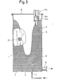
- the first embodiment of a device for forming emulsions shown in FIG. 1 comprises a circular cylindrical container 1 with a flat bottom 2, through which a drive shaft 3 is sealed and concentrically guided, which carries a disk-shaped stirring element 4 at its end located inside the container. Below this stirring element 4 occurs line 5 through the bottom 2 into the interior of the container 1, the outlet point being below the disk-shaped stirring element 4.
- solvent and emulsifier can be introduced into the container from a storage container for solvent and emulsifier by means of a feed pump in a manner not shown, the inflow quantity being adjustable by a metering valve, also not shown in the drawing.
- the upper part of the container 1 is surrounded by a likewise circular cylindrical collecting space 6, the outer diameter of which is larger than that of the container 1 and the underside 7 of which is arranged approximately in the upper third of the container 1.
- the collecting space 6 is closed by means of a cover 8, the closed upper side of the collecting space 6 projecting significantly beyond the upper edge 9 of the container, for example the upper edge 9 can end approximately halfway up the collecting space 6.
- the collecting space 6 In the vicinity of the underside 7, the collecting space 6 has a radially emerging outlet 10.
- a tube 11 is inserted through the cover 8 of the collecting space 6 concentrically to the container into the collecting space 6 and the container 1, the free end 12 of which ends approximately halfway up the container 1.
- This tube 11 has an outlet opening 14 in its end face 13 and further outlet openings 15 in its side wall 16, the outlet openings 15 are arranged in the side wall at different heights; Above the upper edge 9 of the container 1 there are no outlet openings 15 in the side wall.
- the aqueous slurry can be introduced into the container from a slurry device, not shown in the drawing.
- an upwardly emerging ventilation line 17 also emerges through the cover 8, with a conically narrowing region 18, in which there is a conical floating body 19 on the upper side, which together with the conical region 18 closes the ventilation line 17 when the float floats in the liquid. However, it releases the ventilation line 17 when there is air in the ventilation line 17 so that it can escape to the outside.
- the liquid inside the container and to a lesser extent inside the collecting space is set in rotation about the longitudinal axis of the container by the stirring element 4, so that an essentially parabolic liquid level is formed in the container, which is increasingly flatter in the collecting space runs.
- Solvent and emulsifier are introduced into the container from below, and the aqueous slurry through tube 11 from above. A substantial part of the aqueous slurry passes through the frontal exit opening 14 directly into the area above the stirring element 4, in which a particularly intensive mixing takes place, as indicated by the arrows A in FIG. 1. In this area, the concentration of the aqueous slurry is low, which promotes emulsion formation.
- the emulsion formed is driven upward along the container walls, further aqueous slurry entering the emulsion through the side openings 15 in the tube 11 and being emulsified.
- the emulsion has reached the desired composition, with thorough and uniform mixing taking place, since the aqueous slurry is introduced from the stationary tube into the emulsion rotating rapidly around the tube.
- the emulsion calms down and stabilizes, which is then finally discharged through the outlet 10, if necessary, in the drawing Swirl chamber, not shown, can be supplied for their final use.
- the emulsion is subsequently stabilized in the swirl chamber, which can be equipped with baffles.
- the gradual on is important mixture of the aqueous slurry which in the end takes up a larger proportion in volume in the emulsion.
- the concentration of the slurry at the beginning of the emulsion formation is substantially lower than the concentration in the finished emulsion, and this means that the emulsion formation can take place in the desired manner. It is only gradually that the concentration of the aqueous slurry in the emulsion increases, to the extent that the liquid in the container moves upward.
- the container 1 is not circular cylindrical, but the wall of the container 1 has a parabolic shape, the parabola being cut off by the flat bottom 2 at the lower end.
- the collecting space 6 completely surrounds the container 1, so that the underside 7 of the collecting space 6 lies in one plane with the bottom 2 of the container 1.
- the introduction of the aqueous slurry does not take place via a concentrically introduced pipe, but rather via a plurality of feed lines 20 which radially penetrate the collecting space 6 and open into the wall of the container 1 and which are arranged at different heights.
- the aqueous slurry becomes tion first introduced into the space above the stirring element 4 via deep-lying feed lines, in which the concentration of the aqueous slurry is substantially lower than the final concentration in the finished emulsion.
- additional aqueous slurry is subsequently introduced through higher-level feed lines until the final concentration is finally reached.
- a vent line 17a is provided, which in this case does not branch off from the feed line for the aqueous slurry, but is held on the cover 8.
- the feed line has a conically narrowing region 18a and surrounds a floating body 19a which can close the vent line in the region of the conically narrowing region.
- the supply lines 20 are not introduced radially into the container, but tangentially, in a uniform direction of rotation, so that the liquid in the interior of the container is set in rotation by the aqueous slurry introduced becomes. This makes it possible to dispense with a stirring element in the container. Otherwise, the emulsion is formed in the same way as in the exemplary embodiment in FIG. 2.
- the interior of the container and the collecting space is under positive pressure, i.e. the two components fed into the interior are fed under pressure.
Landscapes
- Chemical & Material Sciences (AREA)
- Chemical Kinetics & Catalysis (AREA)
- Mixers Of The Rotary Stirring Type (AREA)
- Detergent Compositions (AREA)
Priority Applications (1)
| Application Number | Priority Date | Filing Date | Title |
|---|---|---|---|
| AT85113281T ATE49512T1 (de) | 1984-11-14 | 1985-10-19 | Vorrichtung zum erzeugen einer stabilen emulsion zur verwendung in reinigungs- und entgiftungsgeraeten. |
Applications Claiming Priority (2)
| Application Number | Priority Date | Filing Date | Title |
|---|---|---|---|
| DE3441529 | 1984-11-14 | ||
| DE19843441529 DE3441529A1 (de) | 1984-11-14 | 1984-11-14 | Vorrichtung zum erzeugen einer stabilen emulsion zur verwendung in reinigungs- und entgiftungsgeraeten |
Publications (3)
| Publication Number | Publication Date |
|---|---|
| EP0182110A2 true EP0182110A2 (fr) | 1986-05-28 |
| EP0182110A3 EP0182110A3 (en) | 1987-05-06 |
| EP0182110B1 EP0182110B1 (fr) | 1990-01-17 |
Family
ID=6250235
Family Applications (1)
| Application Number | Title | Priority Date | Filing Date |
|---|---|---|---|
| EP85113281A Expired - Lifetime EP0182110B1 (fr) | 1984-11-14 | 1985-10-19 | Dispositif de production d'une émulsion stable pour l'utilisation dans les appareils d'épuration et de décontamination |
Country Status (4)
| Country | Link |
|---|---|
| US (1) | US4750843A (fr) |
| EP (1) | EP0182110B1 (fr) |
| AT (1) | ATE49512T1 (fr) |
| DE (2) | DE3441529A1 (fr) |
Cited By (2)
| Publication number | Priority date | Publication date | Assignee | Title |
|---|---|---|---|---|
| EP0306030A1 (fr) * | 1987-09-03 | 1989-03-08 | Matra-Werke Gmbh | Dispositif pour la production en continu d'un mélange fluide de solides et liquides |
| CN111790311A (zh) * | 2020-07-21 | 2020-10-20 | 浙江佳润新材料有限公司 | 一种纺织品用乳液的生产方法 |
Families Citing this family (10)
| Publication number | Priority date | Publication date | Assignee | Title |
|---|---|---|---|---|
| US5403092A (en) * | 1994-02-01 | 1995-04-04 | Eastman Kodak Company | Viscous shear mixing device and method |
| US6019499A (en) * | 1995-04-18 | 2000-02-01 | Advanced Molecular Technologies, Llc | Method of conditioning hydrocarbon liquids and an apparatus for carrying out the method |
| JPH11503818A (ja) | 1995-04-18 | 1999-03-30 | アドバンスト・モレキュラー・テクノロジーズ・リミテッド・ライアビリティ・カンパニー | 流体加熱方法および同方法を実施するための装置 |
| US5599101A (en) * | 1995-09-01 | 1997-02-04 | Pardikes; Dennis G. | Dry polymer processing system |
| US7384183B2 (en) * | 2002-09-06 | 2008-06-10 | Global Ground Support, Llc | Mobile decontamination unit |
| CN101879045A (zh) * | 2006-04-03 | 2010-11-10 | 玛美得股份有限公司 | 油炸机 |
| US20090268547A1 (en) * | 2008-04-14 | 2009-10-29 | Norchem Industries | Devices, systems and methods for dry powder processing |
| JP4798174B2 (ja) * | 2008-05-21 | 2011-10-19 | 株式会社日立プラントテクノロジー | 乳化装置 |
| RU2404466C1 (ru) * | 2009-08-18 | 2010-11-20 | Федеральное государственное унитарное предприятие "Горно-химический комбинат" | Перемешивающее устройство кольцевого аппарата |
| RU2446494C2 (ru) * | 2010-04-30 | 2012-03-27 | Федеральное государственное унитарное предприятие "Горно-химический комбинат" | Пульсационное перемешивающее устройство кольцевого аппарата |
Family Cites Families (10)
| Publication number | Priority date | Publication date | Assignee | Title |
|---|---|---|---|---|
| CA449893A (fr) * | 1948-07-20 | A. Auer George | Appareil de controle de l'agitation de matieres en solution et suspension | |
| DE971250C (de) * | 1954-12-02 | 1958-12-31 | Ruhrchemie Ag | Verfahren zur Behandlung pulverfoermiger Stoffe mit Fluessigkeiten |
| DE1085851B (de) * | 1955-02-28 | 1960-07-28 | Bayer Ag | Vorrichtung zur Herstellung von Loesungen aus pulverfoermigen, insbesondere Stoffen mit niedrigem Schuettgewicht |
| GB994172A (en) * | 1960-05-31 | 1965-06-02 | Maxwell Seely Woosnam | Improvements in or relating to the contacting of fluids and solids |
| US3669900A (en) * | 1969-05-02 | 1972-06-13 | Pacific Vegetable Oil Corp | Method and apparatus for continuous production of oil-in-water emulsions |
| US4106117A (en) * | 1976-05-07 | 1978-08-08 | Waukesha Foundry Company, Inc. | Apparatus for mixing particulate material in a liquid |
| GB2031748B (en) * | 1978-10-09 | 1983-04-27 | British Res Agricult Eng | Continuous mixing |
| US4366142A (en) * | 1979-03-28 | 1982-12-28 | Sadao Kojima | Method and apparatus for the preparation of slaked lime solution |
| US4345841A (en) * | 1980-06-20 | 1982-08-24 | Geosource Inc. | Multi-stage centrifugal mixer |
| US4533123A (en) * | 1984-05-07 | 1985-08-06 | Betz Laboratories, Inc. | Liquid mixing device |
-
1984
- 1984-11-14 DE DE19843441529 patent/DE3441529A1/de not_active Withdrawn
-
1985
- 1985-10-19 EP EP85113281A patent/EP0182110B1/fr not_active Expired - Lifetime
- 1985-10-19 DE DE8585113281T patent/DE3575381D1/de not_active Expired - Fee Related
- 1985-10-19 AT AT85113281T patent/ATE49512T1/de not_active IP Right Cessation
- 1985-11-12 US US06/797,427 patent/US4750843A/en not_active Expired - Fee Related
Cited By (3)
| Publication number | Priority date | Publication date | Assignee | Title |
|---|---|---|---|---|
| EP0306030A1 (fr) * | 1987-09-03 | 1989-03-08 | Matra-Werke Gmbh | Dispositif pour la production en continu d'un mélange fluide de solides et liquides |
| CN111790311A (zh) * | 2020-07-21 | 2020-10-20 | 浙江佳润新材料有限公司 | 一种纺织品用乳液的生产方法 |
| CN111790311B (zh) * | 2020-07-21 | 2022-04-19 | 浙江佳润新材料有限公司 | 一种纺织品用乳液的生产方法 |
Also Published As
| Publication number | Publication date |
|---|---|
| DE3441529A1 (de) | 1986-05-22 |
| US4750843A (en) | 1988-06-14 |
| DE3575381D1 (de) | 1990-02-22 |
| EP0182110B1 (fr) | 1990-01-17 |
| ATE49512T1 (de) | 1990-02-15 |
| EP0182110A3 (en) | 1987-05-06 |
Similar Documents
| Publication | Publication Date | Title |
|---|---|---|
| DE69425895T2 (de) | Vorrichtung und methode zur lösung eines teilchenförmigen feststoffs in eine flüssigkeit | |
| DE69328038T2 (de) | Verfahren und vorrichtung zum lagern und handhaben von abwasserschlämmen | |
| DE2818369A1 (de) | Verfahren und vorrichtung zum behandeln von feinverteiltem schuettgut, insbesondere pulpe | |
| EP0182110B1 (fr) | Dispositif de production d'une émulsion stable pour l'utilisation dans les appareils d'épuration et de décontamination | |
| DE2229903A1 (de) | Wasserbehandlungsvorrichtung | |
| DE2830699A1 (de) | Verfahren zur herstellung einer waessrigen dispersion, die mit einem fuellstoff zur papierherstellung verwendet wird und ein solubilisiertes polymeres bindemittel enthaelt | |
| DE3243671C2 (fr) | ||
| DE69222460T2 (de) | Verfahren und Vorrichtung zur Herstellung wässriger Lösung von gelöschtem Kalk | |
| CH500136A (de) | Verfahren zur Herstellung von Lösungen, Emulsionen oder Suspensionen, insbesondere beim biologischen Reinigen freier Gewässer, und Vorrichtung zur Ausführung des Verfahrens | |
| DE1945773A1 (de) | Verfahren und Vorrichtung zum chargenweisen Mischen | |
| DE60015158T2 (de) | Verfahren zur auslaugung von festen bestandteilen aus schlamm | |
| DE3640655C2 (fr) | ||
| DE3704461A1 (de) | Verfahren und anlage zur aufloesung von papierstoff | |
| DE2047650A1 (de) | Verfahren zur Herstellung eines im wesentlichen klumpenfreien Gemisches | |
| DE3640791A1 (de) | Verfahren und vorrichtung zum dispergieren von zwei phasen bei einer solventextraktion | |
| DE2615540A1 (de) | Verfahren zur erzeugung eines homogenen chemisch-reaktiven systems und einrichtung zur durchfuehrung des verfahrens | |
| EP0013986A1 (fr) | Procédé pour l'élimination de l'ammoniac de solutions ammoniacales, en particulier des eaux de cokerie | |
| DE2741243A1 (de) | Verfahren und vorrichtung zur durchmischung zweier medien | |
| DE2740789A1 (de) | Verfahren und vorrichtung zum kontinuierlichen mechanischen mischen ungleichartiger substanzen | |
| CH342880A (de) | Verfahren und Apparatur zur Herstellung von Schiesspulver | |
| DE2643341C3 (de) | Verfahren zur Herstellung von konzentrierten Natriumchloridlösungen | |
| AT225823B (de) | Verfahren und Vorrichtung zur Gewinnung fester Rußaggregate oder Rußkörper aus einer wässerigen Rußsuspension | |
| DE2940547A1 (de) | Verfahren und vorrichtung zur kontinuierlichen zersetzung einer bruchstueckartigen trockensubstanz, insbesondere einer lignozellulose-substanz | |
| DE2510613C2 (de) | Verfahren und Vorrichtung zum Mischen von zwei Flüssigkeiten | |
| DE2314344C2 (de) | Mischer für die kontinuierliche Aufbereitung von fliesfähigem Mischgut |
Legal Events
| Date | Code | Title | Description |
|---|---|---|---|
| PUAI | Public reference made under article 153(3) epc to a published international application that has entered the european phase |
Free format text: ORIGINAL CODE: 0009012 |
|
| AK | Designated contracting states |
Kind code of ref document: A2 Designated state(s): AT CH DE FR GB IT LI NL |
|
| PUAL | Search report despatched |
Free format text: ORIGINAL CODE: 0009013 |
|
| AK | Designated contracting states |
Kind code of ref document: A3 Designated state(s): AT CH DE FR GB IT LI NL |
|
| 17P | Request for examination filed |
Effective date: 19871002 |
|
| 17Q | First examination report despatched |
Effective date: 19880513 |
|
| GRAA | (expected) grant |
Free format text: ORIGINAL CODE: 0009210 |
|
| AK | Designated contracting states |
Kind code of ref document: B1 Designated state(s): AT CH DE FR GB IT LI NL |
|
| PG25 | Lapsed in a contracting state [announced via postgrant information from national office to epo] |
Ref country code: NL Effective date: 19900117 |
|
| REF | Corresponds to: |
Ref document number: 49512 Country of ref document: AT Date of ref document: 19900215 Kind code of ref document: T |
|
| ITF | It: translation for a ep patent filed | ||
| ET | Fr: translation filed | ||
| GBT | Gb: translation of ep patent filed (gb section 77(6)(a)/1977) | ||
| REF | Corresponds to: |
Ref document number: 3575381 Country of ref document: DE Date of ref document: 19900222 |
|
| NLV1 | Nl: lapsed or annulled due to failure to fulfill the requirements of art. 29p and 29m of the patents act | ||
| PG25 | Lapsed in a contracting state [announced via postgrant information from national office to epo] |
Ref country code: LI Effective date: 19901031 Ref country code: CH Effective date: 19901031 |
|
| PLBE | No opposition filed within time limit |
Free format text: ORIGINAL CODE: 0009261 |
|
| STAA | Information on the status of an ep patent application or granted ep patent |
Free format text: STATUS: NO OPPOSITION FILED WITHIN TIME LIMIT |
|
| 26N | No opposition filed | ||
| REG | Reference to a national code |
Ref country code: CH Ref legal event code: PL |
|
| ITTA | It: last paid annual fee | ||
| PGFP | Annual fee paid to national office [announced via postgrant information from national office to epo] |
Ref country code: FR Payment date: 19930901 Year of fee payment: 9 |
|
| PGFP | Annual fee paid to national office [announced via postgrant information from national office to epo] |
Ref country code: GB Payment date: 19931011 Year of fee payment: 9 |
|
| PG25 | Lapsed in a contracting state [announced via postgrant information from national office to epo] |
Ref country code: GB Effective date: 19941019 |
|
| GBPC | Gb: european patent ceased through non-payment of renewal fee |
Effective date: 19941019 |
|
| PG25 | Lapsed in a contracting state [announced via postgrant information from national office to epo] |
Ref country code: FR Effective date: 19950630 |
|
| REG | Reference to a national code |
Ref country code: FR Ref legal event code: ST |
|
| PGFP | Annual fee paid to national office [announced via postgrant information from national office to epo] |
Ref country code: AT Payment date: 19960925 Year of fee payment: 12 |
|
| PG25 | Lapsed in a contracting state [announced via postgrant information from national office to epo] |
Ref country code: AT Free format text: LAPSE BECAUSE OF NON-PAYMENT OF DUE FEES Effective date: 19971019 |
|
| PGFP | Annual fee paid to national office [announced via postgrant information from national office to epo] |
Ref country code: DE Payment date: 19971125 Year of fee payment: 13 |
|
| PG25 | Lapsed in a contracting state [announced via postgrant information from national office to epo] |
Ref country code: DE Free format text: LAPSE BECAUSE OF NON-PAYMENT OF DUE FEES Effective date: 19990803 |