EP0306030A1 - Dispositif pour la production en continu d'un mélange fluide de solides et liquides - Google Patents
Dispositif pour la production en continu d'un mélange fluide de solides et liquides Download PDFInfo
- Publication number
- EP0306030A1 EP0306030A1 EP88114330A EP88114330A EP0306030A1 EP 0306030 A1 EP0306030 A1 EP 0306030A1 EP 88114330 A EP88114330 A EP 88114330A EP 88114330 A EP88114330 A EP 88114330A EP 0306030 A1 EP0306030 A1 EP 0306030A1
- Authority
- EP
- European Patent Office
- Prior art keywords
- line
- pump
- chamber
- discharge pump
- funnel
- Prior art date
- Legal status (The legal status is an assumption and is not a legal conclusion. Google has not performed a legal analysis and makes no representation as to the accuracy of the status listed.)
- Granted
Links
- 239000007788 liquid Substances 0.000 title claims abstract description 53
- 239000007787 solid Substances 0.000 title claims abstract description 28
- 239000000203 mixture Substances 0.000 title claims abstract description 27
- 239000012530 fluid Substances 0.000 title 1
- 238000002156 mixing Methods 0.000 claims abstract description 33
- 238000010924 continuous production Methods 0.000 claims abstract description 3
- 230000001105 regulatory effect Effects 0.000 claims 1
- 239000000126 substance Substances 0.000 abstract description 3
- 230000015572 biosynthetic process Effects 0.000 abstract 1
- XLYOFNOQVPJJNP-UHFFFAOYSA-N water Substances O XLYOFNOQVPJJNP-UHFFFAOYSA-N 0.000 description 27
- 238000005202 decontamination Methods 0.000 description 8
- 230000003588 decontaminative effect Effects 0.000 description 8
- 235000008733 Citrus aurantifolia Nutrition 0.000 description 5
- 235000011941 Tilia x europaea Nutrition 0.000 description 5
- 239000004571 lime Substances 0.000 description 5
- 239000003995 emulsifying agent Substances 0.000 description 4
- 239000002904 solvent Substances 0.000 description 4
- ZAMOUSCENKQFHK-UHFFFAOYSA-N Chlorine atom Chemical compound [Cl] ZAMOUSCENKQFHK-UHFFFAOYSA-N 0.000 description 3
- 229910052801 chlorine Inorganic materials 0.000 description 3
- 239000000460 chlorine Substances 0.000 description 3
- 239000002245 particle Substances 0.000 description 3
- 239000007921 spray Substances 0.000 description 2
- 230000000903 blocking effect Effects 0.000 description 1
- 238000002485 combustion reaction Methods 0.000 description 1
- 230000002349 favourable effect Effects 0.000 description 1
- 239000000463 material Substances 0.000 description 1
- 238000005259 measurement Methods 0.000 description 1
- 238000000034 method Methods 0.000 description 1
- 238000005192 partition Methods 0.000 description 1
- 230000002093 peripheral effect Effects 0.000 description 1
- 238000005507 spraying Methods 0.000 description 1
- 238000011144 upstream manufacturing Methods 0.000 description 1
Images
Classifications
-
- B—PERFORMING OPERATIONS; TRANSPORTING
- B01—PHYSICAL OR CHEMICAL PROCESSES OR APPARATUS IN GENERAL
- B01F—MIXING, e.g. DISSOLVING, EMULSIFYING OR DISPERSING
- B01F25/00—Flow mixers; Mixers for falling materials, e.g. solid particles
- B01F25/10—Mixing by creating a vortex flow, e.g. by tangential introduction of flow components
-
- B—PERFORMING OPERATIONS; TRANSPORTING
- B01—PHYSICAL OR CHEMICAL PROCESSES OR APPARATUS IN GENERAL
- B01F—MIXING, e.g. DISSOLVING, EMULSIFYING OR DISPERSING
- B01F23/00—Mixing according to the phases to be mixed, e.g. dispersing or emulsifying
- B01F23/50—Mixing liquids with solids
- B01F23/59—Mixing systems, i.e. flow charts or diagrams
Definitions
- the invention relates to a device for the continuous production of a liquid mixture of solids and liquids with a rotationally symmetrical space with at least approximately vertical axis of rotation, in which a rotational flow is generated.
- Granular chlorinated lime is primarily provided as a solid and water, solvents and / or emulsifiers are primarily provided as liquid components, the device as such being intended to generate the required flow of a water-chemical mixture for the purpose of decontaminating terrain strips or equipment .
- solvents and / or emulsifiers are primarily provided as liquid components, the device as such being intended to generate the required flow of a water-chemical mixture for the purpose of decontaminating terrain strips or equipment .
- One difficulty is to evenly mix the granular or lumpy solid, especially chlorine lime, with the water stream, which requires a certain dwell time to dissolve the solid in the water.
- a mixing device in which water is introduced from below into a rotationally symmetrical container with a vertical axis and through one by one coaxial axis rotating disc is set in a rotational flow.
- a liquid stream in which solids are dissolved is fed coaxially from above through a second pipeline, and it is expected that this stream coaxially flowing in from above mixes with the stream flowing in from below, with additional provision being made that from the side connected pipes other liquid components can be supplied.
- the top of the rotationally symmetrical container is limited by an overflow edge. The excess flow passes over this overflow edge into a collecting container surrounding the outside of the rotating container and is discharged into its lower region.
- the contact area of the flow that is to rotate with the wall of the rotating container is much larger than the contact area with the wall of the rotating disk, and which flows form within the rotating container and can be used for the purpose of mixing is very confusing.
- the invention is therefore based on the object of providing a simple but reliable device by means of which a granular, water-soluble solid can be continuously and properly mixed into a liquid stream with a predictable mixing result, even if a very strong or significantly weaker stream is desired at times .
- the rotationally symmetrical space is an annular space which has an overflow edge on the inside, a funnel-shaped collecting basin being arranged below the overflow edge and discharge openings of metering devices for the solid and liquid components being arranged above the overflow edge.
- the entire annular space is preferably covered by a cover which covers the overflow edge and from which a cylindrical part protrudes inwards and downwards, so that a gap is formed between this part which projects inwards and downwards and the wall, the upper edge of which forms the overflow edge, whereby laterally sprayed solid particles cannot get into the water flow due to the overhanging cover wall.
- a rotational flow is formed on this inner wall, on the upper edge of which the overflow edge is formed, and in the funnel located below, into which a certain flow of granular solid and liquid components is fed from above by means of the metering devices becomes.
- the removal of the liquid components is fed.
- the liquid mixture can be removed at the lowest point of the funnel.
- the discharge line can also be connected preferably tangentially above the lowest point of the funnel.
- the connection can be made in the direction of flow or counter to the direction of flow, in the latter case a strong turbulence and thus mixing is achieved before entering the discharge pipe.
- the embodiment according to claim 2 makes it possible to achieve the rotational flow in the ring container in a simple manner, namely by virtue of the fact that the water supply line or the water supply lines open tangentially into the annular space, it being advantageous if they come from below or from the lateral peripheral wall flow out without protruding into the annular space, so that the flow enters tangentially without pipe parts protruding into the container. It is also conceivable to supply liquid components in the annular space.
- the water flow is expediently fed to the ring container by a pump which generates a pressure. It is particularly advantageous if the delivery line of the pump is split into two branch lines, both of which are connected to the annular space via supply lines. A shut-off valve and a flow control valve are arranged in series in each branch line, the two flow control valves being designed for currents of different sizes. It is also possible to regulate the delivery flow of the pump via its speed or via a single flow control valve in the delivery line.
- the pumps of the individual chambers can be designed so that their delivery volume considerably exceeds the continuously required amount of liquid mixture, so that a flow division is possible and the much larger amount of liquid mixture is pumped around in the chamber belonging to the pump, while only the continuously required amount of liquid mixture is passed on to the next chamber and finally reaches the discharge pump after passing the last pump.
- the individual drives can be individually controlled and switched on or off.
- a flow meter in the delivery line of the pump for supplying water to the annular space between the latter and the annular space and to control the drive motors of the metering devices and the pump at the outlet of the funnel depending on its measurement signal.
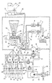
- the pump 1 draws in from the water tank 2 and delivers into the delivery line 3.
- the pump 1 is driven by the electric motor 4.
- the delivery line 3 branches into the two branch lines 5 and 6, a shut-off valve 7 and a flow control valve 8 being arranged in series in the branch line 5.
- a shut-off valve 9 and a flow control valve 10 are connected in series in the branch line 6.
- a line 11 leads and starting from the flow control valve 10
- a line 12 leads into the toroidal annular space 13, which has an inner overflow edge 14.
- the annular space 13 is covered by a cover 15, the projection 16 of which covers the overflow edge 14.
- the inner wall 17 of the annular space 13 is cylindrical. Connects to them down a funnel 18 at the lowest point, a line 19 is connected.
- a second pump 20 which leads to a second pump 20 which is driven by an electric motor 21 and which conveys into a delivery line 22.
- a directional valve 23 is arranged, from which a line 24 and a second line 25 extend, the second line 25 being connected to the suction line 26 of a discharge pump 27.
- the line 24 leads into a first chamber 29 of a mixing container 28, which in this example consists of three chambers 29, 30, 31 connected in series.
- Pumps 35, 36, 37 driven by electric motors 32, 33, 34 are assigned to the chambers.
- the chambers are separated from one another by partition walls 39, 40 of different heights.
- the height of the intermediate walls 39, 40 increases starting with the first chamber 29 with each next chamber following in the series connection, so that the intermediate wall between the penultimate and the last chamber is the highest.
- Suction lines 41, 42, 43 belonging to the pumps 35, 36, 37 are each arranged in such a way that the liquid mixture is sucked into the chamber bottom.
- the delivery line of each pump is divided into two.
- a line section with a larger cross section leads back into the chamber to the chamber floor, where the respective suction opening of the suction line is also located.
- a second line section with a smaller cross-section opens into the next chamber connected in series, above the maximum possible liquid level there. Only the continuously required amount of liquid mixture is passed from chamber to chamber. Due to the division of the current, the majority remains in constant circulation, since the different heights of the intermediate walls of the chamber always cause an overflow back to the first chamber 29. This ensures intensive mixing with sufficient residence and dissolving times.
- Switches 44, 45, 46 located in the chambers control the minimum level of the liquid mixture of each chamber located above the suction openings of the suction lines 41, 42, 43. If the minimum level is reached in a chamber, the pump belonging to the upstream chamber is switched on. Another switch 47 controls the maximum liquid level in the mixing container 28. This switch 47 is therefore located in the first chamber 29. It switches off the pump 20 when the maximum level is reached.
- switches 48, 49 for checking the liquid level which switch the electric motors 4, 50, 51 of the water pump 1, a solids metering device 52 and a metering device 53 of the liquid component on or off when certain levels are undershot or exceeded.
- a plurality of metering devices can also be provided for the solid and liquid components.
- the second line part with a smaller cross section of the delivery line of the pump 37 of the last chamber 31 is connected through line 54 to the suction line 26 of the discharge pump 27.
- the line 54 can also be shut off by means of a switchable directional valve 55.
- the discharge pump 27, preferably an internal combustion engine powered portable pump, is connected by a delivery line 56, in which a switchable directional valve 57 is arranged, at a certain switching position of the directional valve 57 to the discharge devices, for example spray devices, which are no longer shown in the drawing.
- the delivery line 56 and suction line 26 are short-circuited via a return line 58, the electric motors 4, 21, 32, 33, 34, 50, 51 of the pumps 1, 20, 35, 36, 37 and Dosing devices 52, 53 are switched off.
- a further line 59 is connected, which is provided with a switchable directional valve 60, in the switch position of which the line 59 is blocked.
- the line 59 is directly connected to the suction line 26 of the discharge pump 27.
- the solids metering device 52 essentially consists of a feed hopper 61 which is filled with the solids to be mixed, the solids being kept in motion by means of a rotary vane 62, and a metering device 63 at the lower region of the loading hopper 61, the discharge screw 64 of which is controlled by the controllable electric motor 50 is driven.
- the metering device 53 of the liquid component consists of a conveying device 65 which is driven by means of the controllable electric motor 51 and which flows from a container 66 via a shut-off valve 67 to the liquid component to be mixed.
- Two containers 66 are expediently arranged vertically one behind the other, a shut-off valve 67 being provided on each of the containers 66 and one container 66 being used to hold solvents and the other being used to hold emulsifiers, or a mixture of solvent and emulsifier being premixed in both .
- Attached to the directional control valve 57 is an electrical switching element (not shown in the drawing) which is connected to the actuating lever of the directional control valve 57 and is coupled to a voltage source. Electrical lines are laid between the switching element and the electric motors of the mixing device.
- the operation of the mixing device is as follows:
- the pump 1 draws water from the water tank 2 and conveys it through the delivery line 3 into the branch lines 5 and 6.
- the two flow control valves 8 and 10 are set to differently sized flows, the flow control valve 8 preferably being on a small current is set as required for device decontamination and the flow control valve 10 is set for a large current as required for site decontamination. If the shut-off valve 9 is closed and the shut-off valve 7 is open, only a small current flows into the annular space 13 of the mixing device, while when the shut-off valve 7 is closed and the shut-off valve 9 is open, a much larger current flows as required for the decontamination of the site is. For the site decontamination, preferably both shut-off valves 7 and 9 can be opened.
- the flow control valve 8 is designed for a flow of 20 l / min and the flow control valve 10 for a flow of 180 l / min.
- a certain allocated amount of solvent and / or emulsifier enters the rotating water stream and mixes with it and the chlorine lime.
- Devices known per se such as sieves, centrifugal separators or the like, can ensure that no lime lump particles are torn through the suction line 19 to the second pump 20.
- the water-chemical mixture is supplied to the mixing tank 28 with the corresponding position of the directional valve 23 in the delivery line 22, where it is circulated in the manner already described. From there, the liquid mixture passes through the delivery line 54 provided with a shut-off directional valve 55 and the suction line 26 to the discharge pump 27, which is connected to the spray devices for decontamination.
- the directional control valve 57 in the delivery line 56 of the discharge pump 27 is switched into the circulating position, so that the discharge pump 27 pumps the remaining quantity in circulation.
- the electrical switching element connected to the actuating lever of the directional control valve 57 ensures that all electric motors are switched off. The switch-on or switch-on takes place completely through the directional control valve 57 or the electrical switching element connected to it.
- the electric motors can be switched on and off individually by additional, arbitrarily actuated switches, which are no longer shown in the drawing.
- the electric motors 4 and 21 of the pumps 1 and 20 and the motor 50 of the solids metering device 52 run and the directional control valve 23 is in a switching state, not shown in the drawing, in which the lines 22 and 25 are connected to one another.
- the directional valve 55 is in the blocking position.
- the directional control valve 60 is in the open position, so that the funnel 18 and discharge pump 27 are additionally connected via the line 59. In this way, the maximum flow rate of liquid mixture can be applied.
- the electric motors 4, 21, 51 of the pumps 1, 20 and the metering device 53 for the liquid component run.
- the directional valve 23 connects the delivery line 22 of the pump 20 directly to the suction line 26 of the discharge pump 27.
- the directional control valve 23 is switched so that the liquid flowing through the line 22 is passed via the mixing container 28 to the discharge pump 27.
- the electric motors 32, 33, 34 of the pumps 35, 36, 37 of the mixing container chambers 29, 30, 31 are also switched on.
Landscapes
- Chemical & Material Sciences (AREA)
- Chemical Kinetics & Catalysis (AREA)
- Dispersion Chemistry (AREA)
- Physical Or Chemical Processes And Apparatus (AREA)
- Accessories For Mixers (AREA)
- Feeding, Discharge, Calcimining, Fusing, And Gas-Generation Devices (AREA)
- Mixers Of The Rotary Stirring Type (AREA)
Priority Applications (1)
| Application Number | Priority Date | Filing Date | Title |
|---|---|---|---|
| AT88114330T ATE85237T1 (de) | 1987-09-03 | 1988-09-02 | Einrichtung zum kontinuierlichen erzeugen einer fluessigen mischung von fest- und fluessigstoffen. |
Applications Claiming Priority (2)
| Application Number | Priority Date | Filing Date | Title |
|---|---|---|---|
| DE19873729527 DE3729527A1 (de) | 1986-11-14 | 1987-09-03 | Einrichtung zum kontinuierlichen erzeugen einer fluessigen mischung von fest- und fluessigstoffen |
| DE3729527 | 1987-09-03 |
Publications (2)
| Publication Number | Publication Date |
|---|---|
| EP0306030A1 true EP0306030A1 (fr) | 1989-03-08 |
| EP0306030B1 EP0306030B1 (fr) | 1993-02-03 |
Family
ID=6335174
Family Applications (1)
| Application Number | Title | Priority Date | Filing Date |
|---|---|---|---|
| EP88114330A Expired - Lifetime EP0306030B1 (fr) | 1987-09-03 | 1988-09-02 | Dispositif pour la production en continu d'un mélange fluide de solides et liquides |
Country Status (10)
| Country | Link |
|---|---|
| US (1) | US4859072A (fr) |
| EP (1) | EP0306030B1 (fr) |
| JP (1) | JPS6470136A (fr) |
| AT (1) | ATE85237T1 (fr) |
| CZ (1) | CZ277748B6 (fr) |
| DD (1) | DD273010A5 (fr) |
| DE (1) | DE3878096D1 (fr) |
| IL (1) | IL87641A (fr) |
| SU (1) | SU1720477A3 (fr) |
| UA (1) | UA7200A1 (fr) |
Cited By (2)
| Publication number | Priority date | Publication date | Assignee | Title |
|---|---|---|---|---|
| WO2000056432A1 (fr) * | 1999-03-19 | 2000-09-28 | Termoelettronica S.P.A. | Dispositif permettant de mettre des matieres en suspension dans un liquide et systeme permettant de preparer des melanges liquide-matieres destines a la teinture au moyen de ce dispositif |
| DE19955008A1 (de) * | 1999-03-23 | 2000-10-12 | Gna Ges Fuer Nasaufbereitungst | Einrichtung zum Dispergieren eines Feststoffs in einer Flüssigkeit |
Families Citing this family (28)
| Publication number | Priority date | Publication date | Assignee | Title |
|---|---|---|---|---|
| DE4024538A1 (de) * | 1990-08-02 | 1992-02-06 | Babcock Werke Ag | Vorrichtung zum vermischen eines dispersen feststoffes mit einer fluessigkeit |
| JP3136969B2 (ja) * | 1995-01-26 | 2001-02-19 | 富士電機株式会社 | 調理材料の定量供給装置 |
| US5718507A (en) * | 1995-07-25 | 1998-02-17 | Gian; Michael | Dosifying apparatus for mixing a batch of mixed liquid product from separate bulk sources of supply of a liquid carrier and an additive |
| US5840108A (en) * | 1996-07-26 | 1998-11-24 | Karras; George C. | Method and apparatus for continuous preparation of corrugating adhesive |
| US5951161A (en) * | 1997-08-29 | 1999-09-14 | Elf Atochem North America, Inc. | Apparatus for preparation of tank mixtures for heat sensitive biofungicides |
| US6254267B1 (en) * | 1997-11-06 | 2001-07-03 | Hydrotreat, Inc. | Method and apparatus for mixing dry powder into liquids |
| EP1097637A1 (fr) * | 1999-11-02 | 2001-05-09 | Maschinenfabrik Rau GmbH | Distributeur |
| US20030165078A1 (en) * | 2000-05-05 | 2003-09-04 | Aggarwal Rakesh Kumar | Mixer and method for mixing liquids or a solid and a liquid |
| US6250793B1 (en) * | 2000-05-23 | 2001-06-26 | Michael Gian | Animal feed additive application utilizing foam |
| WO2003086604A1 (fr) * | 2002-04-11 | 2003-10-23 | Mobius Technologies, Inc. | Systeme et procede de commande de petrissage d'une pate |
| US6860289B2 (en) * | 2002-04-11 | 2005-03-01 | Robert Donald Villwock | Surge tank |
| US20030233937A1 (en) * | 2002-04-11 | 2003-12-25 | Mobius Technologies, Inc., A California Corporation | Apparatus and method for continuously removing air from a mixture of ground polyurethane particles and a polyol liquid |
| US7029162B2 (en) * | 2002-04-11 | 2006-04-18 | Mobius Technologies, Inc. | Process and apparatus for continuous mixing of slurry with removal of entrained bubbles |
| US6994464B2 (en) * | 2002-04-11 | 2006-02-07 | Mobius Technologies, Inc | Control system and method for continuous mixing of slurry with removal of entrained bubbles |
| US20030227817A1 (en) * | 2002-04-11 | 2003-12-11 | Mobius Technologies, Inc., A California Corporation | Mixer |
| US6979116B2 (en) * | 2002-08-30 | 2005-12-27 | Wastewater Solutions, Inc. | Apparatus for injecting dry bulk amendments for water and soil treatment |
| US7628529B2 (en) * | 2005-07-29 | 2009-12-08 | Toyota Motor Engineering & Manufacturing North America, Inc. | Systems and methods for mixing paint |
| EP1932457A1 (fr) * | 2006-12-11 | 2008-06-18 | Nestec S.A. | Dispositif d'entrée de position et système informatique |
| US20100027371A1 (en) * | 2008-07-30 | 2010-02-04 | Bruce Lucas | Closed Blending System |
| GB201101075D0 (en) | 2011-01-21 | 2011-03-09 | Labminds Ltd | Automated solution dispenser |
| US9296568B2 (en) * | 2011-12-30 | 2016-03-29 | Agco Corporation | Accuracy of fertilizer dispensed through a fixed opening |
| GB2519890B (en) * | 2012-07-18 | 2019-01-16 | Labminds Ltd | Automated solution dispenser |
| WO2016097278A1 (fr) * | 2014-12-18 | 2016-06-23 | Tetra Laval Holdings & Finance S.A. | Unité de mélange et procédé destiné au mélange |
| JP2018507103A (ja) | 2015-02-06 | 2018-03-15 | ラブマインズ リミテッド | 自動化溶液ディスペンサ |
| JP6548424B2 (ja) * | 2015-03-30 | 2019-07-24 | 兵神装備株式会社 | 粉体混合機及び粉体混合方法 |
| JP6835364B2 (ja) * | 2019-06-25 | 2021-02-24 | 兵神装備株式会社 | 粉体混合機及び粉体混合方法 |
| AU2023340906A1 (en) * | 2022-09-16 | 2025-04-03 | H.J. Heinz Company Brands Llc | Food processing system and methods |
| CN117869793A (zh) * | 2024-01-11 | 2024-04-12 | 上海佳豪船海工程研究设计有限公司 | 一种非接触式液体流动连接结构 |
Citations (6)
| Publication number | Priority date | Publication date | Assignee | Title |
|---|---|---|---|---|
| DE2259647A1 (de) * | 1972-12-06 | 1974-06-12 | Mono Pumps Ltd | Verfahren und vorrichtung zum mischen eines pulvers mit einer fliessfaehigen substanz |
| US4125334A (en) * | 1977-11-17 | 1978-11-14 | Coal Industry (Patents) Limited | Apparatus for mixing two flowable substances |
| DE2900931A1 (de) * | 1978-08-24 | 1980-03-13 | Geosource Inc | Verfahren und vorrichtung zum mischen fliessfaehigen materials mit festkoerpern |
| GB2031748A (en) * | 1978-10-09 | 1980-04-30 | British Res Agricult Eng | Continuous mixing |
| EP0182110A2 (fr) * | 1984-11-14 | 1986-05-28 | Alfred Kärcher GmbH & Co. | Dispositif de production d'une émulsion stable pour l'utilisation dans les appareils d'épuration et de décontamination |
| EP0236883A2 (fr) * | 1986-03-06 | 1987-09-16 | Odenwaldwerke Rittersbach GmbH Fahrzeugbau und Katastrophenschutzsysteme | Dispositif pour obtenir une émulsion désintoxaquée pour des agents de guerre chimique |
Family Cites Families (5)
| Publication number | Priority date | Publication date | Assignee | Title |
|---|---|---|---|---|
| US3870283A (en) * | 1972-12-07 | 1975-03-11 | Mono Pumps Engineering Limited | Method and apparatus for mixing a powder with a flowable substance |
| US4493249A (en) * | 1982-11-12 | 1985-01-15 | Bunn-O-Matic Corporation | Apparatus for dissolving soluble coffee |
| US4778280A (en) * | 1986-06-25 | 1988-10-18 | Stranco, Inc. | Mixing apparatus |
| DE8630501U1 (de) * | 1986-11-14 | 1988-03-31 | Matra-Werke GmbH, 60314 Frankfurt | Einrichtung zum Erzeugen einer Mischung in Wasser |
| DE8630502U1 (de) * | 1986-11-14 | 1988-04-28 | Matra-Werke GmbH, 60314 Frankfurt | Einrichtung zum Erzeugen eines Stromes einer Mischung von Wasser mit einem wasserlöslichen Feststoff und einem oder mehreren flüssigen Komponenten |
-
1988
- 1988-08-10 CZ CS885556A patent/CZ277748B6/cs unknown
- 1988-08-30 US US07/237,957 patent/US4859072A/en not_active Expired - Fee Related
- 1988-08-31 UA UA4356338A patent/UA7200A1/uk unknown
- 1988-08-31 SU SU884356338A patent/SU1720477A3/ru active
- 1988-09-01 IL IL87641A patent/IL87641A/xx not_active IP Right Cessation
- 1988-09-01 DD DD88319395A patent/DD273010A5/de not_active IP Right Cessation
- 1988-09-02 EP EP88114330A patent/EP0306030B1/fr not_active Expired - Lifetime
- 1988-09-02 DE DE8888114330T patent/DE3878096D1/de not_active Expired - Fee Related
- 1988-09-02 JP JP63218622A patent/JPS6470136A/ja active Pending
- 1988-09-02 AT AT88114330T patent/ATE85237T1/de not_active IP Right Cessation
Patent Citations (6)
| Publication number | Priority date | Publication date | Assignee | Title |
|---|---|---|---|---|
| DE2259647A1 (de) * | 1972-12-06 | 1974-06-12 | Mono Pumps Ltd | Verfahren und vorrichtung zum mischen eines pulvers mit einer fliessfaehigen substanz |
| US4125334A (en) * | 1977-11-17 | 1978-11-14 | Coal Industry (Patents) Limited | Apparatus for mixing two flowable substances |
| DE2900931A1 (de) * | 1978-08-24 | 1980-03-13 | Geosource Inc | Verfahren und vorrichtung zum mischen fliessfaehigen materials mit festkoerpern |
| GB2031748A (en) * | 1978-10-09 | 1980-04-30 | British Res Agricult Eng | Continuous mixing |
| EP0182110A2 (fr) * | 1984-11-14 | 1986-05-28 | Alfred Kärcher GmbH & Co. | Dispositif de production d'une émulsion stable pour l'utilisation dans les appareils d'épuration et de décontamination |
| EP0236883A2 (fr) * | 1986-03-06 | 1987-09-16 | Odenwaldwerke Rittersbach GmbH Fahrzeugbau und Katastrophenschutzsysteme | Dispositif pour obtenir une émulsion désintoxaquée pour des agents de guerre chimique |
Cited By (2)
| Publication number | Priority date | Publication date | Assignee | Title |
|---|---|---|---|---|
| WO2000056432A1 (fr) * | 1999-03-19 | 2000-09-28 | Termoelettronica S.P.A. | Dispositif permettant de mettre des matieres en suspension dans un liquide et systeme permettant de preparer des melanges liquide-matieres destines a la teinture au moyen de ce dispositif |
| DE19955008A1 (de) * | 1999-03-23 | 2000-10-12 | Gna Ges Fuer Nasaufbereitungst | Einrichtung zum Dispergieren eines Feststoffs in einer Flüssigkeit |
Also Published As
| Publication number | Publication date |
|---|---|
| CZ277748B6 (en) | 1993-04-14 |
| IL87641A (en) | 1992-09-06 |
| EP0306030B1 (fr) | 1993-02-03 |
| DE3878096D1 (de) | 1993-03-18 |
| US4859072A (en) | 1989-08-22 |
| UA7200A1 (uk) | 1995-06-30 |
| DD273010A5 (de) | 1989-11-01 |
| IL87641A0 (en) | 1989-02-28 |
| ATE85237T1 (de) | 1993-02-15 |
| CS555688A3 (en) | 1992-11-18 |
| JPS6470136A (en) | 1989-03-15 |
| SU1720477A3 (ru) | 1992-03-15 |
Similar Documents
| Publication | Publication Date | Title |
|---|---|---|
| EP0306030B1 (fr) | Dispositif pour la production en continu d'un mélange fluide de solides et liquides | |
| DE69328038T2 (de) | Verfahren und vorrichtung zum lagern und handhaben von abwasserschlämmen | |
| DE3002720A1 (de) | Verfahren und vorrichtung zum mischen von fluessigen und festen stoffen | |
| DE2526462B2 (de) | Verfahren und Vorrichtung zum hydraulischen Fördern von Feststoffen | |
| EP0385926B1 (fr) | Dispositif pour distribuer des substances protégeant les plantes | |
| DE6910964U (de) | Mischvorrichtung | |
| DE3429412A1 (de) | Mischvorrichtung | |
| DE3729527A1 (de) | Einrichtung zum kontinuierlichen erzeugen einer fluessigen mischung von fest- und fluessigstoffen | |
| EP0236883B1 (fr) | Dispositif pour obtenir une émulsion désintoxaquée pour des agents de guerre chimique | |
| EP0264900A2 (fr) | Etape de prédéshydratation de boues et de produits similaires | |
| DE8630501U1 (de) | Einrichtung zum Erzeugen einer Mischung in Wasser | |
| DE1782327B2 (de) | Chargenmischer | |
| DE1913940B1 (de) | Mischvorrichtung | |
| DE1941831A1 (de) | Mischmaschine | |
| CH668366A5 (de) | Vorrichtung zum herstellen von mehrkomponentengemischen. | |
| DE1912501U (de) | Vorrichtung zur beseitigung von abfaellen. | |
| DE2523374A1 (de) | Vorrichtung zur kontinuierlichen herstellung von angemachtem moertel | |
| DE8630502U1 (de) | Einrichtung zum Erzeugen eines Stromes einer Mischung von Wasser mit einem wasserlöslichen Feststoff und einem oder mehreren flüssigen Komponenten | |
| EP0200961A2 (fr) | Dispositif et méthode pour doser des matériaux fluides | |
| DE3536090C1 (en) | Bitumen preparation plant | |
| DE2124701A1 (de) | Feinmahl werk | |
| DE2629209C2 (de) | Vorrichtung zum hydraulischen Fördern eines Schüttguts, wie Kohle oder Erz | |
| DE3621284A1 (de) | Anordnung mit einem zumischer zum zumischen von chemikalien zu einem fluessigkeitsstrom | |
| DE3615992C2 (fr) | ||
| DE3308712A1 (de) | Verfahren und mischer zum kontinuierlichen mischen von trockenem feingut, insbesondere pulverfoermigen oder koernigem kunststoff |
Legal Events
| Date | Code | Title | Description |
|---|---|---|---|
| PUAI | Public reference made under article 153(3) epc to a published international application that has entered the european phase |
Free format text: ORIGINAL CODE: 0009012 |
|
| AK | Designated contracting states |
Kind code of ref document: A1 Designated state(s): AT CH DE FR GB LI NL SE |
|
| 17P | Request for examination filed |
Effective date: 19890222 |
|
| 17Q | First examination report despatched |
Effective date: 19910214 |
|
| GRAA | (expected) grant |
Free format text: ORIGINAL CODE: 0009210 |
|
| AK | Designated contracting states |
Kind code of ref document: B1 Designated state(s): AT CH DE FR GB LI NL SE |
|
| REF | Corresponds to: |
Ref document number: 85237 Country of ref document: AT Date of ref document: 19930215 Kind code of ref document: T |
|
| GBT | Gb: translation of ep patent filed (gb section 77(6)(a)/1977) |
Effective date: 19930215 |
|
| REF | Corresponds to: |
Ref document number: 3878096 Country of ref document: DE Date of ref document: 19930318 |
|
| ET | Fr: translation filed | ||
| PLBE | No opposition filed within time limit |
Free format text: ORIGINAL CODE: 0009261 |
|
| STAA | Information on the status of an ep patent application or granted ep patent |
Free format text: STATUS: NO OPPOSITION FILED WITHIN TIME LIMIT |
|
| 26N | No opposition filed | ||
| EAL | Se: european patent in force in sweden |
Ref document number: 88114330.9 |
|
| PGFP | Annual fee paid to national office [announced via postgrant information from national office to epo] |
Ref country code: GB Payment date: 19960827 Year of fee payment: 9 |
|
| PGFP | Annual fee paid to national office [announced via postgrant information from national office to epo] |
Ref country code: FR Payment date: 19960910 Year of fee payment: 9 |
|
| PGFP | Annual fee paid to national office [announced via postgrant information from national office to epo] |
Ref country code: AT Payment date: 19960912 Year of fee payment: 9 |
|
| PGFP | Annual fee paid to national office [announced via postgrant information from national office to epo] |
Ref country code: SE Payment date: 19960917 Year of fee payment: 9 |
|
| PGFP | Annual fee paid to national office [announced via postgrant information from national office to epo] |
Ref country code: CH Payment date: 19960919 Year of fee payment: 9 |
|
| PGFP | Annual fee paid to national office [announced via postgrant information from national office to epo] |
Ref country code: NL Payment date: 19960930 Year of fee payment: 9 |
|
| PGFP | Annual fee paid to national office [announced via postgrant information from national office to epo] |
Ref country code: DE Payment date: 19961002 Year of fee payment: 9 |
|
| PG25 | Lapsed in a contracting state [announced via postgrant information from national office to epo] |
Ref country code: GB Free format text: LAPSE BECAUSE OF NON-PAYMENT OF DUE FEES Effective date: 19970902 Ref country code: AT Free format text: LAPSE BECAUSE OF NON-PAYMENT OF DUE FEES Effective date: 19970902 |
|
| PG25 | Lapsed in a contracting state [announced via postgrant information from national office to epo] |
Ref country code: SE Free format text: LAPSE BECAUSE OF NON-PAYMENT OF DUE FEES Effective date: 19970903 |
|
| PG25 | Lapsed in a contracting state [announced via postgrant information from national office to epo] |
Ref country code: LI Free format text: LAPSE BECAUSE OF NON-PAYMENT OF DUE FEES Effective date: 19970930 Ref country code: FR Free format text: THE PATENT HAS BEEN ANNULLED BY A DECISION OF A NATIONAL AUTHORITY Effective date: 19970930 Ref country code: CH Free format text: LAPSE BECAUSE OF NON-PAYMENT OF DUE FEES Effective date: 19970930 |
|
| PG25 | Lapsed in a contracting state [announced via postgrant information from national office to epo] |
Ref country code: NL Free format text: LAPSE BECAUSE OF NON-PAYMENT OF DUE FEES Effective date: 19980401 |
|
| GBPC | Gb: european patent ceased through non-payment of renewal fee |
Effective date: 19970902 |
|
| REG | Reference to a national code |
Ref country code: CH Ref legal event code: PL |
|
| NLV4 | Nl: lapsed or anulled due to non-payment of the annual fee |
Effective date: 19980401 |
|
| PG25 | Lapsed in a contracting state [announced via postgrant information from national office to epo] |
Ref country code: DE Free format text: LAPSE BECAUSE OF NON-PAYMENT OF DUE FEES Effective date: 19980603 |
|
| EUG | Se: european patent has lapsed |
Ref document number: 88114330.9 |
|
| REG | Reference to a national code |
Ref country code: FR Ref legal event code: ST |