EP0182241A2 - Dispositif pour la filature à friction - Google Patents
Dispositif pour la filature à friction Download PDFInfo
- Publication number
- EP0182241A2 EP0182241A2 EP85114323A EP85114323A EP0182241A2 EP 0182241 A2 EP0182241 A2 EP 0182241A2 EP 85114323 A EP85114323 A EP 85114323A EP 85114323 A EP85114323 A EP 85114323A EP 0182241 A2 EP0182241 A2 EP 0182241A2
- Authority
- EP
- European Patent Office
- Prior art keywords
- thread
- friction
- tube
- take
- friction elements
- Prior art date
- Legal status (The legal status is an assumption and is not a legal conclusion. Google has not performed a legal analysis and makes no representation as to the accuracy of the status listed.)
- Granted
Links
Images


Classifications
-
- D—TEXTILES; PAPER
- D01—NATURAL OR MAN-MADE THREADS OR FIBRES; SPINNING
- D01H—SPINNING OR TWISTING
- D01H4/00—Open-end spinning machines or arrangements for imparting twist to independently moving fibres separated from slivers; Piecing arrangements therefor; Covering endless core threads with fibres by open-end spinning techniques
- D01H4/48—Piecing arrangements; Control therefor
- D01H4/52—Piecing arrangements; Control therefor for friction spinning
Definitions
- the present invention relates to a method for friction spinning, in which the fibers are twisted together on a thread formation line by rotation of two friction elements which are driven in the same direction and form a wedge gap, and are drawn off as thread, and a device for carrying out this method.
- the fibers are fed from a disintegration device via a fiber channel into the wedge gap between the two friction elements designed as rollers.
- the rotational movement of the two rollers twists the fibers together to form a thread and, in continuation of the wedge gap, is drawn out of the wedge gap by a thread draw-off tube.
- a pair of rollers is provided as the thread take-off device.
- the friction elements are arranged relative to one another in such a way that the thread is as deep as possible in the wedge gap. In this way, the slip between the friction elements and the thread is kept low.
- the thread end After a thread break, the thread end must be reinserted into the spinning device, i.e. the thread must be inserted with its open end through the thread draw-off tube between the two friction rollers into the wedge gap.
- the thread end it is difficult to put the thread end straight into the narrow wedge gap. This requires complex additional devices and air ducts.
- the object of the invention is therefore to provide a method and a device for friction spinning which ensure simple and safe piecing, but which also give reliable rotation during the subsequent spinning process.
- the thread is not only placed in the thread formation line, but that when the thread runs off the friction elements, its contact pressure is increased against at least one of the friction elements. This can influence the rotation and the appearance of the thread.
- a thread guide element arranged immediately after the friction elements can be moved transversely to the thread take-off direction, so that this can bring the thread into the position desired for the return delivery, piecing and spinning.
- the thread guide element in the wedge gap plane Through the movement of the thread guide element in the wedge gap plane, the thread is drawn into the wedge gap and thus an increased influence of the friction elements is achieved.
- the thread can be returned unhindered to the piecing position by the counter movement of the thread guide element. It is advantageous if, in addition to its movement along the wedge gap plane, the thread guide element can be moved transversely to the wedge gap plane in order to bring the thread against the friction element rotating into the wedge gap.
- the thread take-off tube can be moved axially parallel to the thread forming line or alternatively pivotable about an axis running transverse to the thread take-off direction.
- the thread take-off tube is concentric with the thread forming line of the friction elements in the direction to the end of the thread formation line delimiting the thread take-off tube. This can be achieved by pivoting or by guiding the thread take-off tube in a link guide.
- the effect of a change in the contact pressure between the thread and the friction element can be further increased in that one or both of the facing thread contact surfaces of the friction elements and the thread guide element has a surface with an increased coefficient of friction and / or a profile. It is not necessary that this thread contact surface with the increased coefficient of friction and / or the profiling is constantly in the thread take-off area. If this should be disadvantageous during the normal spinning process, it can be provided according to the invention that this thread contact surface can only be brought into the thread take-off path by a movement of the thread guide element.
- the subject matter of the invention is simple in structure and enables the spinning process to be influenced in its various working phases.
- the friction between the thread and the friction elements will be completely eliminated.
- the contact pressure between the thread and the friction elements can be graded or continuously varied. On the one hand, this increases the piecing security and the strength of the piecing.
- the character of the yarn, in particular the roughness of the yarn can be varied in many ways.
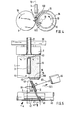
- the friction spinning device contains two rotationally symmetrical friction elements in the form of two cylindrical friction rollers 1 and 10, which form a wedge gap 11 or spider gusset.
- the two friction rollers 1 and 10 are perforated and vacuumed in the area of the wedge gap 11 during spinning. For this purpose, they are connected to a suction device in a manner not shown.
- the two friction rollers 1 and 10 are mounted in a bearing 2 and are driven in the same direction by a tangential belt 20 (see arrow 13).
- the friction rollers 1 and 10 are assigned a fiber feed device (not shown), from which the fibers 30 are guided into the wedge gap 11 of the friction rollers 1 and 10 via a fiber feed channel 3.
- the thread 47 is drawn off from the wedge gap 11 by a thread pulling device 4, which consists of a drive roller 40 and a pressure roller 41 pressed against the drive roller 40 by a loading means.
- the thread 47 is wound on a spool, not shown.
- a suction device 21 is arranged at the level of the wedge gap 11.
- a thread guide element designed as a thread take-off tube 5.
- the thread take-off tube 5 is pivotally mounted about an axis 50 transversely to the thread take-off direction (arrow 42).
- An electromagnet 6 is provided as the drive and is connected to the thread draw-off tube via a coupling member 60.
- This coupling member 60 is surrounded by a compression spring 61, which is on the one hand on the thread take-off tube 5 and others supports on the other hand on the housing of the electromagnet 6, so that the thread draw-off tube 5 is pivoted into its broken position II when the electromagnet 6 has fallen off.
- the thread guiding element 5, which is designed as a thread take-off tube 5 is pivoted parallel to the plane of representation in the wedge gap plane 12 (see FIG. 2), so that during this pivoting movement, a thread 47 drawn off by the thread take-off tube 5 is shifted in the wedge gap plane 12.
- Wedge gap plane 12 is understood to mean the plane whose position is determined by the common tangent of the two friction rollers 1, 10.
- the thread take-off tube 5 is pivoted into the position marked III in FIG. 1 .
- the thread take-off device 4 is driven in the opposite direction to the normal thread take-off direction, so that the thread 47 is returned in the opposite direction to the arrow 42 to the friction elements 1 and 10.
- the thread end leaving the thread take-off tube 5 in the direction of the friction elements 1 and 10 is now outside the thread formation line 43 and is made using one of the suction means direction 21 incoming suction air flow brought into the piecing position.
- the thread take-off tube 5 is brought back into the position I by the relaxing compression spring 61.
- the thread 47 is placed in the thread formation line 43 to bind the fibers.
- the fiber feed into the wedge gap 10 is switched on again and the direction of rotation of the thread draw-off device 4 is reversed.
- the thread 47 is then withdrawn from the wedge gap 11 with the continuous integration of the fibers 30 continuously fed to the wedge gap 11.
- a stepping drive 62 (see, for example, FIG. 7) is provided, by means of which the thread take-off tube 5 via the coupling member 60 optionally in the one or the other direction can be pivoted over the desired path.
- the rotation of the thread 47 can be changed practically continuously.
- the size of the contact pressure which leads to optimal results when piecing or spinning itself, depends on various factors such as surface and speed of rotation of the friction rollers 1 and 10, fiber material to be spun, yarn thickness etc.
- a guide 45 (FIG. 5) can be connected to the thread take-off tube 5, which guides the thread 47 at least at the outlet of this thread take-off device 4 axially to the clamping line between the drive roller 40 and the pressure roller 41 takes.
- the thread draw-off device 4 or an auxiliary draw-off device (not shown) can also be pivoted together with the thread draw-off tube 5.
- the thread draw-off tube 5 is moved along the wedge gap plane 12 during these pivoting movements, but other directions of movement can also be defined for the thread draw-off tube 5.
- 3 shows a friction spinning device in which the thread take-off tube 5 receives, in addition to this movement along the wedge gap plane 12, a movement component (arrow 520) against the friction roller 10 (see arrow 13) which rotates into the wedge gap 11.
- a movement component arrow 520
- the friction roller 10 is designed as a friction roller.
- This friction roller 10 presses the thread 47 resting against it with increased contact pressure as it rotates in the direction of arrow 13 into the wedge gap 11.
- the axis 50 shown in FIG. 1 for the thread draw-off tube 5 can be mounted correspondingly deviating from the perpendicular to the wedge gap plane 42.
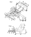
- Fig. 7 shows another embodiment in which the thread take-off tube 5 is mounted in an eccentric disc 53 which is rotatably supported by a bearing 54. Part of the axis of rotation of the eccentric disk 53 is designed as a pinion 55, with which a rack 63 is engaged. This rack 63 is driven by a stepper drive 62 in either direction.
- the thread take-off tube 5 When the eccentric disk 53 is adjusted along the double arrow 522, the thread take-off tube 5 always maintains its axis-parallel position to the thread formation line 43. As shown in FIG. 7, the axis of rotation of the eccentric disk 53 is arranged such that when the thread take-off tube 5 moves from the position I shown by the solid line to the position III, for. B. for piecing, the thread take-off tube 5 practically moves along the wedge gap plane 12 (FIG. 2) while the thread take-off tube 5 during a movement from its position I - in the extension of the thread formation line 43 (FIG. 1) - into the position II receives a movement component against the friction roller 10 turning into the wedge gap 11 (see arrow 13).
- the thread contact surfaces 140 and 150 facing the thread take-off tube 5 are provided with a profile 16 in the form of notches in the area of these peripheral edges 14 and 15. Instead of notches, webs, grits etc. can also be provided. It is also possible, in addition to or instead of a profiling 16, to provide that the thread contact surfaces 140 and 150 have a surface with an increased coefficient of friction in the region of the peripheral edges 14 and 15. For this purpose, for example, this area can be provided with a rubber covering, etc.
- the mouth 51 (FIG. 5) of the thread draw-off tube 5 is moved out of the extended thread formation line 43 during its movement in the direction against the friction roller 10 rotating in the direction (arrow 13) against the wedge gap 11 (FIG. 4: arrow 522).
- the friction roller 10 thus takes the thread 47 to the wedge gap 11.
- the thread take-off tube 5 shows another example of such an embodiment.
- the thread take-off tube 5 is concentric with the end 46 facing the thread take-off tube 5 the thread formation line 43 is pivotable.
- the thread take-off tube 5 is guided in a link guide 64 with the aid of a sliding block 500.
- the thread take-off tube 5 is connected via a coupling member 60 to a step drive 62, by means of which it can be adjusted along the link guide 64.
- the thread take-off tube 5 is in the position I shown in broken lines, in which the returned thread 47 assumes an extended position from the take-off device 4 to the thread-forming line 43.
- the thread guide tube 5 is brought into position II with the aid of the stepping drive 62.
- the thread contact surface 150 of the friction roller 15 thereby brought into the thread take-off path, so that the rotational entrainment is not only caused by a change in the contact pressure of the thread 47 on the peripheral edge 15 of the friction roller 10, but is improved by this additionally applied to the thread 47 thread contact surface 150.
- a pivot axis (not shown) for the thread draw-off tube 5 can also be provided, which extends through the end of the thread forming line 43 facing the thread draw-off device 4.
- a thread contact surface 140 or 150 with an increased coefficient of friction or with a profiling 16 is only together Hang with the friction rollers 1 and 10 have been described. If desired, however, instead of or in addition to one or more such thread contact surfaces 150 on the friction rollers 1 and 10, the mouth 51 of the thread take-off tube 5 facing the friction rollers 1, 10 can also have such a thread contact surface (not shown). It is also possible to give this thread contact surface a conically widening shape so that this thread contact surface can only be brought into the thread take-off path by moving the thread take-off tube 5.
- a thread take-off tube 5 which is movable transversely to the thread take-off path is always shown as the thread guide element.
- the thread guide element can be used as a thread guide eyelet (not shown) which can be displaced transversely to the thread take-off path.
- FIG. 6 shows a modified friction spinning device with a stationary thread take-off tube 5, in the mouth 51 of which a biconical chamber 57 is provided which is enlarged compared to the remaining inner diameter of the thread take-off tube 5.
- a thread guide element designed as a bracket 58.
- This bracket 58 is in the position I shown in such a position with respect to the thread 47 that it assumes an extended position between the thread formation line 43 and the thread take-off tube 5.
- the bracket 58 is brought into the position II in the direction of the arrow 52.
- the bracket 58 thus shifts the thread 47 so that it is on one side against the circumference edges 14 and 15 (Fig. 7) of the friction rollers 1 and 10 and on the other side against the edge 59 between chamber 57 and bore 56 of the thread take-off tube 5 is pressed.
- the thread guiding element can also have a different shape, e.g. the shape of a fork, etc.
- the thread guide element for example a bracket 58
- the edge 59 of the chamber 57 or also the edge 590 delimiting the chamber 57 in the direction of the friction rollers 1 and 10 can be used as a thread contact surface with an increased friction coefficient or a profile 16 (see FIG. 7). If several such thread contact surfaces 590, 58 and 59 are provided, these can also be designed differently in order to influence the roughness or smoothness of the thread 47. For example, the thread 47 experiences a kind of polishing or smoothing through smooth edges.
- the thread formation line 43 is formed solely by the friction elements designed as friction rollers 1 and 10. As shown in FIG. 8, however, it is also possible, as a modification thereof, to provide a stationary fiber collecting surface 7, which is followed by the two friction elements 8 driven in the same direction in the thread take-off direction (arrow 42), so that the thread formation line 43 forms the wedge gap 11 between the friction elements 8 and the fiber collecting surface 7 comprises.
- This fiber collecting surface 7 is vacuumed.
- it is connected via a plurality of bores 70 to a suction chamber 71, which is connected to a line 72.
- a further suction chamber 74 is provided, which is connected to a line 75.
- the two lines 72 and 75 can alternately be connected via a changeover valve 76 to a suction line 77, which in turn is connected to a vacuum source 73.
- a drive 90 is assigned to the changeover valve 76.
- the friction elements 8 are designed as a pair of friction disks which are driven in the same sense in a manner not shown.
- a thread guiding element designed as a thread take-off tube 5 is arranged between the friction elements 8 and the thread take-off device 4 designed as a pair of rollers and is pivotally mounted about an axis 50 at its end facing the thread take-off device 4.
- This thread take-off tube 5 is connected to a drive 91 via a drive rod 92.
- the drives 90 and 91 are connected in terms of control to a control device 9 which makes the desired adjustments of the changeover valve 76 or of the thread take-off tube 5 as a function of a manual control or a predetermined program.
- the drive 91 is actuated by the control device 9, which drives the thread take-off tube 5 from the position shown in dashed lines to that with a solid line Position swiveled.
- the control device 9 effects a changeover of the changeover valve 76 from the position indicated by dashed lines to the position shown, in which the vacuum source 73 is connected to the suction chamber 74.
- the thread 47 is returned between the friction elements 8 outside the wedge gap 11 when the pair of rollers forming the thread take-off device 4 is turned back. He can thus freely follow the air flow flowing into the suction chamber 74.
- the thread take-off tube 5 and the changeover valve 76 are brought back into their spinning position (dashed position). The end of the thread 47 is drawn against the fiber collecting surface 7 by the suction air flow now acting again in the suction chamber 71. In addition, the thread 47 now again comes into the wedge gap 11 formed by the friction elements 8 and thus in contact with these friction elements 8. In a conventional and therefore not described manner, the fiber feed and insertion of the thread take-off are now controlled.
- the drive 91 pushes the thread 47 with the help of the thread take-off tube 5, independently of the piecing program, into the wedge gap 11.
- the rotation and the appearance of the thread 47 can be influenced by appropriate shaping or surface design of the friction elements 8 and / or the thread take-off tube or by a combination thereof.
- the friction elements 8 can also be designed as longer rollers etc. It is also possible to provide more than just two friction elements 8, whereby these - with respect to the thread take-off direction - can be arranged either in the same or in offset planes (see FIG. 8) with respect to one another.
Landscapes
- Engineering & Computer Science (AREA)
- Mechanical Engineering (AREA)
- Textile Engineering (AREA)
- Spinning Or Twisting Of Yarns (AREA)
Applications Claiming Priority (2)
| Application Number | Priority Date | Filing Date | Title |
|---|---|---|---|
| DE3441678 | 1984-11-15 | ||
| DE19843441678 DE3441678A1 (de) | 1984-11-15 | 1984-11-15 | Verfahren und vorrichtung zum friktionsspinnen |
Publications (3)
| Publication Number | Publication Date |
|---|---|
| EP0182241A2 true EP0182241A2 (fr) | 1986-05-28 |
| EP0182241A3 EP0182241A3 (en) | 1987-05-27 |
| EP0182241B1 EP0182241B1 (fr) | 1990-10-31 |
Family
ID=6250322
Family Applications (1)
| Application Number | Title | Priority Date | Filing Date |
|---|---|---|---|
| EP85114323A Expired - Lifetime EP0182241B1 (fr) | 1984-11-15 | 1985-11-11 | Dispositif pour la filature à friction |
Country Status (8)
| Country | Link |
|---|---|
| US (1) | US4679388A (fr) |
| EP (1) | EP0182241B1 (fr) |
| CN (1) | CN85108994A (fr) |
| DE (2) | DE3441678A1 (fr) |
| GB (1) | GB2169624B (fr) |
| HK (1) | HK33989A (fr) |
| IN (1) | IN166603B (fr) |
| SG (1) | SG589G (fr) |
Families Citing this family (2)
| Publication number | Priority date | Publication date | Assignee | Title |
|---|---|---|---|---|
| GB8827367D0 (en) * | 1988-11-23 | 1988-12-29 | Lawrence C A | Spinning of yarn |
| DE4142636C1 (en) * | 1991-12-21 | 1993-03-18 | Rieter Ingolstadt Spinnereimaschinenbau Ag, 8070 Ingolstadt, De | Open=end friction spinning machine - has two friction rolls connected to suction source, yarn storage unit front opening etc., providing guide to wedge gap without curling during spinning |
Family Cites Families (14)
| Publication number | Priority date | Publication date | Assignee | Title |
|---|---|---|---|---|
| DE2554102A1 (de) * | 1975-12-02 | 1977-06-16 | Fritz Stahlecker | Offenend-spinnmaschine mit wenigstens einem verfahrbaren wartungsgeraet |
| DE2810184A1 (de) * | 1978-03-09 | 1979-09-13 | Barmag Barmer Maschf | Open-end-spinnvorrichtung |
| DE3047987C2 (de) * | 1980-01-28 | 1986-01-23 | Ernst Dr. Linz Fehrer | Vorrichtung zum Herstellen eines Garnes |
| DE3167885D1 (en) * | 1980-02-16 | 1985-02-07 | Hollingsworth Uk Ltd | Apparatus and method of open-end spinning yarn |
| DE3117443A1 (de) * | 1981-05-02 | 1982-11-25 | W. Schlafhorst & Co, 4050 Mönchengladbach | Verfahren und vorrichtung zum offenend-spinnen |
| CH655956A5 (de) * | 1981-05-02 | 1986-05-30 | Schlafhorst & Co W | Verfahren und vorrichtung zum offenend-spinnen. |
| AT382403B (de) * | 1981-11-18 | 1987-02-25 | Fehrer Textilmasch | Vorrichtung zum abziehen eines fadens von einer spinnstelle |
| DE3300637A1 (de) * | 1983-01-11 | 1984-07-12 | Fritz 7347 Bad Überkingen Stahlecker | Oe-friktionsspinnvorrichtung |
| EP0109236B2 (fr) * | 1982-11-09 | 1988-07-06 | Hollingsworth (U.K.) Limited | Cylindres avec aspérités pour machine à filer à friction |
| DE3305621A1 (de) * | 1983-02-18 | 1984-08-23 | Fritz 7347 Bad Überkingen Stahlecker | Oe-friktionsspinnmaschine |
| DE3315034A1 (de) * | 1983-04-26 | 1984-10-31 | Fritz 7347 Bad Überkingen Stahlecker | Verfahren und vorrichtung zum anspinnen an einem spinnaggregat einer oe-friktionsspinnmaschine |
| DE3315983A1 (de) * | 1983-05-02 | 1984-11-08 | Fritz 7347 Bad Überkingen Stahlecker | Oe-friktionsspinnvorrichtung |
| DE3317369A1 (de) * | 1983-05-13 | 1984-11-15 | W. Schlafhorst & Co, 4050 Mönchengladbach | Verfahren und vorrichtung zur inbetriebnahme einer friktionsspinnmaschine |
| DE3318687C2 (de) * | 1983-05-21 | 1995-07-06 | Schlafhorst & Co W | Verfahren und Vorrichtung zur Inbetriebnahme eines Friktionsspinnaggregats |
-
1984
- 1984-11-15 DE DE19843441678 patent/DE3441678A1/de not_active Ceased
-
1985
- 1985-11-09 CN CN85108994A patent/CN85108994A/zh active Pending
- 1985-11-11 EP EP85114323A patent/EP0182241B1/fr not_active Expired - Lifetime
- 1985-11-11 DE DE8585114323T patent/DE3580337D1/de not_active Expired - Lifetime
- 1985-11-14 GB GB08528058A patent/GB2169624B/en not_active Expired
- 1985-11-14 US US06/797,816 patent/US4679388A/en not_active Expired - Fee Related
- 1985-11-20 IN IN935/MAS/85A patent/IN166603B/en unknown
-
1989
- 1989-01-04 SG SG5/89A patent/SG589G/en unknown
- 1989-04-20 HK HK339/89A patent/HK33989A/xx unknown
Also Published As
| Publication number | Publication date |
|---|---|
| EP0182241B1 (fr) | 1990-10-31 |
| SG589G (en) | 1989-06-02 |
| DE3580337D1 (de) | 1990-12-06 |
| GB8528058D0 (en) | 1985-12-18 |
| GB2169624A (en) | 1986-07-16 |
| DE3441678A1 (de) | 1986-05-22 |
| GB2169624B (en) | 1988-09-07 |
| CN85108994A (zh) | 1986-07-02 |
| EP0182241A3 (en) | 1987-05-27 |
| US4679388A (en) | 1987-07-14 |
| IN166603B (fr) | 1990-06-09 |
| HK33989A (en) | 1989-04-28 |
Similar Documents
| Publication | Publication Date | Title |
|---|---|---|
| DE1560302C3 (de) | Offen-End-Spinnvorrichtung | |
| DE2130724C3 (de) | Fadenabzugskanal an einer Offenend-Spinnvorrichtung | |
| WO2002038842A1 (fr) | Dispositif d'un metier a filer destine a comprimer un assemblage de fibres | |
| CH674855A5 (fr) | ||
| CH648874A5 (de) | Vorrichtung zur herstellung von effektgarn. | |
| EP0182241B1 (fr) | Dispositif pour la filature à friction | |
| WO2002042535A1 (fr) | Dispositif sur un metier a filer pour la compression d'un ruban de fibres | |
| DE3300636A1 (de) | Oe-friktionsspinnvorrichtung | |
| DE2010314A1 (de) | Vorrichtung zum Abzug und Aufwickeln von Garn bei Spinneinheiten von Maschinen zur Garnherstellung nach einem pneumatischmechanischen Verfahren, insbesondere mit Hilfe einer Unterdruck-Spinnkammer | |
| DE10154127A1 (de) | Vorrichtung an einer Spinnmaschine zum Verdichten eines Faserverbandes | |
| DE10332711B4 (de) | Riemen für Wickelvorrichtung | |
| EP1143056B1 (fr) | Guide fil pour métier à tricoter rectiligne | |
| DE3323189A1 (de) | Vorrichtung zum oe-friktionspinnen | |
| EP0686713B1 (fr) | Doigt presseur | |
| DE19528727C2 (de) | Offen-End-Rotorspinnmaschine | |
| DE3217083C2 (fr) | ||
| DE102006006504B4 (de) | Streckverfahren und Streckwerk zur Verfeinerung von Fasermaterial | |
| DE102020118327A1 (de) | Verfahren und Vorrichtung zur Falschdrahteinleitung sowie Spinnmaschine | |
| DE3321228A1 (de) | Vorrichtung zum oe-friktionsspinnen | |
| DE3123753A1 (de) | "friktionsfalschdraller" | |
| DE10063727A1 (de) | Armierung für einen Saugkanal einer Faserbündelungseinrichtung einer Spinnmaschine | |
| DE3331197C2 (fr) | ||
| DE3527212C2 (fr) | ||
| DE321020C (de) | Ringspinnmaschine, bei der der Faden zwischen den Zufuehrwalzen und dem Laeufer Drallerhaelt und eine Bremsvorrichtung die Spannung des oberen Fadenteils vermindert | |
| DE10051413A1 (de) | Spinnmaschine mit einer Verdichtungseinrichtung |
Legal Events
| Date | Code | Title | Description |
|---|---|---|---|
| PUAI | Public reference made under article 153(3) epc to a published international application that has entered the european phase |
Free format text: ORIGINAL CODE: 0009012 |
|
| AK | Designated contracting states |
Kind code of ref document: A2 Designated state(s): CH DE FR IT LI |
|
| PUAL | Search report despatched |
Free format text: ORIGINAL CODE: 0009013 |
|
| AK | Designated contracting states |
Kind code of ref document: A3 Designated state(s): CH DE FR IT LI |
|
| ITCL | It: translation for ep claims filed |
Representative=s name: INGG. GUZZI RAVIZZA |
|
| EL | Fr: translation of claims filed | ||
| 17P | Request for examination filed |
Effective date: 19870701 |
|
| 17Q | First examination report despatched |
Effective date: 19881122 |
|
| ITF | It: translation for a ep patent filed | ||
| GRAA | (expected) grant |
Free format text: ORIGINAL CODE: 0009210 |
|
| AK | Designated contracting states |
Kind code of ref document: B1 Designated state(s): CH DE FR IT LI |
|
| ET | Fr: translation filed | ||
| REF | Corresponds to: |
Ref document number: 3580337 Country of ref document: DE Date of ref document: 19901206 |
|
| PLBE | No opposition filed within time limit |
Free format text: ORIGINAL CODE: 0009261 |
|
| STAA | Information on the status of an ep patent application or granted ep patent |
Free format text: STATUS: NO OPPOSITION FILED WITHIN TIME LIMIT |
|
| 26N | No opposition filed | ||
| PGFP | Annual fee paid to national office [announced via postgrant information from national office to epo] |
Ref country code: FR Payment date: 19911106 Year of fee payment: 7 |
|
| ITTA | It: last paid annual fee | ||
| PGFP | Annual fee paid to national office [announced via postgrant information from national office to epo] |
Ref country code: CH Payment date: 19911205 Year of fee payment: 7 |
|
| PG25 | Lapsed in a contracting state [announced via postgrant information from national office to epo] |
Ref country code: LI Effective date: 19921130 Ref country code: CH Effective date: 19921130 |
|
| PG25 | Lapsed in a contracting state [announced via postgrant information from national office to epo] |
Ref country code: FR Effective date: 19930730 |
|
| REG | Reference to a national code |
Ref country code: CH Ref legal event code: PL |
|
| REG | Reference to a national code |
Ref country code: FR Ref legal event code: ST |
|
| PGFP | Annual fee paid to national office [announced via postgrant information from national office to epo] |
Ref country code: DE Payment date: 19931006 Year of fee payment: 9 |
|
| PG25 | Lapsed in a contracting state [announced via postgrant information from national office to epo] |
Ref country code: DE Effective date: 19950801 |