EP0182324A2 - Dispositif pour guider l'agent de refroidissement pour une chemise de cylindre refroidi par liquide - Google Patents
Dispositif pour guider l'agent de refroidissement pour une chemise de cylindre refroidi par liquide Download PDFInfo
- Publication number
- EP0182324A2 EP0182324A2 EP85114581A EP85114581A EP0182324A2 EP 0182324 A2 EP0182324 A2 EP 0182324A2 EP 85114581 A EP85114581 A EP 85114581A EP 85114581 A EP85114581 A EP 85114581A EP 0182324 A2 EP0182324 A2 EP 0182324A2
- Authority
- EP
- European Patent Office
- Prior art keywords
- cylinder tube
- liquid
- cooled cylinder
- helical spring
- tube according
- Prior art date
- Legal status (The legal status is an assumption and is not a legal conclusion. Google has not performed a legal analysis and makes no representation as to the accuracy of the status listed.)
- Withdrawn
Links
Images

Classifications
-
- F—MECHANICAL ENGINEERING; LIGHTING; HEATING; WEAPONS; BLASTING
- F02—COMBUSTION ENGINES; HOT-GAS OR COMBUSTION-PRODUCT ENGINE PLANTS
- F02F—CYLINDERS, PISTONS OR CASINGS, FOR COMBUSTION ENGINES; ARRANGEMENTS OF SEALINGS IN COMBUSTION ENGINES
- F02F1/00—Cylinders; Cylinder heads
- F02F1/02—Cylinders; Cylinder heads having cooling means
- F02F1/10—Cylinders; Cylinder heads having cooling means for liquid cooling
- F02F1/16—Cylinder liners of wet type
-
- F—MECHANICAL ENGINEERING; LIGHTING; HEATING; WEAPONS; BLASTING
- F02—COMBUSTION ENGINES; HOT-GAS OR COMBUSTION-PRODUCT ENGINE PLANTS
- F02F—CYLINDERS, PISTONS OR CASINGS, FOR COMBUSTION ENGINES; ARRANGEMENTS OF SEALINGS IN COMBUSTION ENGINES
- F02F1/00—Cylinders; Cylinder heads
- F02F1/02—Cylinders; Cylinder heads having cooling means
- F02F1/10—Cylinders; Cylinder heads having cooling means for liquid cooling
- F02F1/14—Cylinders with means for directing, guiding or distributing liquid stream
-
- F—MECHANICAL ENGINEERING; LIGHTING; HEATING; WEAPONS; BLASTING
- F02—COMBUSTION ENGINES; HOT-GAS OR COMBUSTION-PRODUCT ENGINE PLANTS
- F02B—INTERNAL-COMBUSTION PISTON ENGINES; COMBUSTION ENGINES IN GENERAL
- F02B3/00—Engines characterised by air compression and subsequent fuel addition
- F02B3/06—Engines characterised by air compression and subsequent fuel addition with compression ignition
Definitions
- the invention relates to a liquid-cooled cylinder tube of an internal combustion engine, in particular a diesel internal combustion engine according to the preamble of claim 1.
- the invention has for its object to provide a cost-effective, helical coolant guide around the cylinder barrel of an internal combustion engine with simple means.
- a helical coolant channel is formed by the helical spring inserted into the cooling gap between the housing and the cylinder tube and fixed in the cooling gap under radial tension.
- Such a coil spring can be used in any internal combustion engine, the pitch of the turns and the number of turns of the coil spring being easily adaptable to the respective cooling requirements.
- the coil spring is designed according to the desired heat transfer coefficient.
- the coil spring lies largely tightly against one wall of the cooling gap and is at a short distance from the other wall. In this way it is ensured that, in addition to the helical flow, an axial partial flow along the cylinder can also be achieved, as a result of which a further increase in the heat transfer coefficient is achieved.
- the outer diameter of the helical spring is preferably larger than the inner diameter of the receiving bore in the housing, so that the helical spring rests on the housing wall under radial tension. Since the coil spring also has a gap with the cylinder tube, the cylinder tube can be used without hindrance after the coil spring has been inserted.
- the cross section of the helical spring wire is preferably rectangular, in particular square, with a side wall of the cross section abutting a wall of the cooling gap and thus giving a relatively large contact surface.
- This cylindrical housing part has a circumferential shoulder 6 in the upper edge for receiving a radially outward-pointing ring flange 4 of the cylinder tube 2.
- the flange 4 has such a radial extension that between the cylindrical inner wall 8 of the housing 1 and the cylindrical outer wall 7 of the cylinder tube 2 a cooling gap 5 is formed.
- a helical spring 3 is inserted, the spring wire of which has a rectangular, preferably the square cross section shown in the exemplary embodiment.
- the coil spring 3 is under radial tension with its turns largely close to the cylindrical inner wall 8 of the housing 1.
- the sides of the cross section are aligned parallel or at right angles to the side wall 8.
- the inner surface of the coil spring or its windings is at a distance s from the cylindrical outer wall of the cylinder tube, as a result of which there is an axial partial flow along the cylinder tube.
- This axial partial flow builds up in addition to the helical flow in the cooling channel between the individual turns of the coil spring 3, which have a distance d from one another, which determines the height of the cooling channel.
- the convection forced in this way serves the increased heat transfer from the cylinder tube to the flow through Coolant. This increase in heat transfer is particularly advantageous in the case of cooling liquids which have a poorer heat transfer property than water.
- FIG. 1 has the advantage that the coil spring 3 can be inserted into the cylindrical housing part 1 of the internal combustion engine before the cylinder tube 2 is inserted, and the cylinder tube can be pushed into the center of the coil spring 3 without hindrance, since the inside diameter of the coil spring is larger than is the outer diameter of the cylinder tube 2.
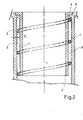
- the basic design of the exemplary embodiment according to FIG. 2 corresponds to that according to FIG. 1, the same reference numerals being used.
- the coil spring used in Fig. 2 is under radial tension on the cylinder tube 2 and has a distance s to the cylindrical inner wall 8 of the housing 1.
- the helical spring in the unloaded state has an outer diameter that is larger than the inner diameter of the cylindrical wall 8 of the housing part 1. 2, the inner diameter of the coil spring in the unloaded state is smaller than the outer diameter of the cylinder tube 2.
- the distance d between adjacent turns of the coil spring 3 may be expedient to provide the distance d between adjacent turns of the coil spring 3 differently.
- the distance d in the upper part of the cylinder tube (in the area of the combustion chamber) could be smaller than in the lower area.
- a helical spring with a progressive pitch, for example, has this course. Through this out education takes into account the greater incidence of heat from the combustion chamber. A greater heat dissipation is thus achieved at the end of the cylinder tube 2 facing the combustion chamber.
Landscapes
- Engineering & Computer Science (AREA)
- Chemical & Material Sciences (AREA)
- Combustion & Propulsion (AREA)
- Mechanical Engineering (AREA)
- General Engineering & Computer Science (AREA)
- Cylinder Crankcases Of Internal Combustion Engines (AREA)
- Springs (AREA)
Applications Claiming Priority (2)
| Application Number | Priority Date | Filing Date | Title |
|---|---|---|---|
| DE3442676 | 1984-11-23 | ||
| DE19843442676 DE3442676A1 (de) | 1984-11-23 | 1984-11-23 | Kuehlmittelfuehrung fuer ein fluessigkeitsgekuehltes zylinderrohr |
Publications (2)
| Publication Number | Publication Date |
|---|---|
| EP0182324A2 true EP0182324A2 (fr) | 1986-05-28 |
| EP0182324A3 EP0182324A3 (fr) | 1987-04-22 |
Family
ID=6250931
Family Applications (1)
| Application Number | Title | Priority Date | Filing Date |
|---|---|---|---|
| EP85114581A Withdrawn EP0182324A3 (fr) | 1984-11-23 | 1985-11-16 | Dispositif pour guider l'agent de refroidissement pour une chemise de cylindre refroidi par liquide |
Country Status (4)
| Country | Link |
|---|---|
| US (1) | US4667635A (fr) |
| EP (1) | EP0182324A3 (fr) |
| JP (1) | JPS61171865A (fr) |
| DE (1) | DE3442676A1 (fr) |
Cited By (5)
| Publication number | Priority date | Publication date | Assignee | Title |
|---|---|---|---|---|
| EP0206124A3 (en) * | 1985-06-19 | 1987-08-19 | Klockner-Humboldt-Deutz Aktiengesellschaft | Internal-combustion engine with at least one liquid cooled cylinder |
| EP1930564A1 (fr) * | 2006-11-22 | 2008-06-11 | Toyota Jidosha Kabushiki Kaisha | Appareil pour le contrôle du transfert thermique avec un fluide thermique pour refroidir un moteur à combustion interne |
| US7765917B2 (en) | 2007-01-12 | 2010-08-03 | Black & Decker Inc. | Air compressor |
| EP2963274A1 (fr) * | 2014-07-01 | 2016-01-06 | Aisin Seiki Kabushiki Kaisha | Moteur a combustion interne |
| CN108691684A (zh) * | 2017-03-30 | 2018-10-23 | 大众汽车有限公司 | 气缸曲轴箱和具有这种气缸曲轴箱的内燃机 |
Families Citing this family (6)
| Publication number | Priority date | Publication date | Assignee | Title |
|---|---|---|---|---|
| DE3601383A1 (de) * | 1986-01-18 | 1987-07-23 | Kloeckner Humboldt Deutz Ag | Kurbelgehaeuse mit eingegossenen kuehlraeumen |
| DE3632159A1 (de) * | 1986-09-22 | 1988-03-31 | Kloeckner Humboldt Deutz Ag | Brennkraftmaschine |
| US5092283A (en) * | 1991-04-26 | 1992-03-03 | Holt Stephen G | Method and device for reducing corrosion in internal combustion engines |
| US5469817A (en) * | 1994-09-01 | 1995-11-28 | Cummins Engine Company, Inc. | Turbulator for a liner cooling jacket |
| DE19818589C2 (de) * | 1998-04-25 | 2000-04-20 | Daimler Chrysler Ag | Brennkraftmaschine |
| CN104948333A (zh) * | 2015-07-13 | 2015-09-30 | 常州市宏硕电子有限公司 | 水冷气缸套 |
Family Cites Families (13)
| Publication number | Priority date | Publication date | Assignee | Title |
|---|---|---|---|---|
| US1682357A (en) * | 1928-08-28 | sperry | ||
| GB601894A (en) * | 1945-10-10 | 1948-05-13 | Harry Ralph Ricardo | Improvements in or relating to cylinders for internal combustion engines |
| FR553461A (fr) * | 1921-08-19 | 1923-05-24 | Gen Electric Co Ltd | Perfectionnements aux moteurs à combustion interne |
| DE577185C (de) * | 1931-02-07 | 1933-05-30 | Rudolf Pawlikowski Dipl Ing | Zylinderbauart fuer Brennkraftmaschinen |
| US2151698A (en) * | 1936-03-27 | 1939-03-28 | Jr William Harper | Internal combustion engine |
| DE675098C (de) * | 1936-05-10 | 1939-04-28 | Daimler Benz Akt Ges | Kuehleinrichtung fuer Zylinder von Brennkraftmaschinen, Kompressoren o. dgl. |
| FR928901A (fr) * | 1945-10-10 | 1947-12-11 | Perfectionnements aux cylindres de moteurs à combustion interne | |
| FR943045A (fr) * | 1947-03-11 | 1949-02-24 | Perfectionnements apportés aux procédés et dispositifs pour le refroidissement des moteurs à combustion interne | |
| DE818710C (de) * | 1949-11-01 | 1951-10-29 | Daimler Benz Ag | Zylinder oder Zylinderlaufbuechse, insbesondere fuer Brennkraftmaschinen |
| DE1020212B (de) * | 1953-12-30 | 1957-11-28 | Nsu Werke Ag | Zylinder fuer Brennkraftmaschinen |
| DE1916096A1 (de) * | 1969-03-28 | 1970-10-08 | Daimler Benz Ag | Zylinderblock fuer fluessigkeitsgekuehlte Brennkraftmaschinen mit eingesetzter Zylinderlaufbuechse |
| NL7004500A (fr) * | 1970-03-28 | 1971-09-30 | ||
| IT1115349B (it) * | 1977-06-13 | 1986-02-03 | Brighigna Mario | Motore a combustione interna raffreddato mediante l'olio di lubrificazione |
-
1984
- 1984-11-23 DE DE19843442676 patent/DE3442676A1/de not_active Withdrawn
-
1985
- 1985-11-16 EP EP85114581A patent/EP0182324A3/fr not_active Withdrawn
- 1985-11-19 JP JP60257914A patent/JPS61171865A/ja active Pending
- 1985-11-21 US US06/800,404 patent/US4667635A/en not_active Expired - Fee Related
Cited By (5)
| Publication number | Priority date | Publication date | Assignee | Title |
|---|---|---|---|---|
| EP0206124A3 (en) * | 1985-06-19 | 1987-08-19 | Klockner-Humboldt-Deutz Aktiengesellschaft | Internal-combustion engine with at least one liquid cooled cylinder |
| EP1930564A1 (fr) * | 2006-11-22 | 2008-06-11 | Toyota Jidosha Kabushiki Kaisha | Appareil pour le contrôle du transfert thermique avec un fluide thermique pour refroidir un moteur à combustion interne |
| US7765917B2 (en) | 2007-01-12 | 2010-08-03 | Black & Decker Inc. | Air compressor |
| EP2963274A1 (fr) * | 2014-07-01 | 2016-01-06 | Aisin Seiki Kabushiki Kaisha | Moteur a combustion interne |
| CN108691684A (zh) * | 2017-03-30 | 2018-10-23 | 大众汽车有限公司 | 气缸曲轴箱和具有这种气缸曲轴箱的内燃机 |
Also Published As
| Publication number | Publication date |
|---|---|
| US4667635A (en) | 1987-05-26 |
| EP0182324A3 (fr) | 1987-04-22 |
| JPS61171865A (ja) | 1986-08-02 |
| DE3442676A1 (de) | 1986-05-28 |
Similar Documents
| Publication | Publication Date | Title |
|---|---|---|
| DE19622257B4 (de) | Luft-Dielektrik-Koaxialkabel mit hohlem Abstandselement | |
| DE2834614A1 (de) | Einheit aus einer kugel-keilwellenverbindung und einer welle | |
| DE2120923A1 (de) | Anker für Gleichstrommaschinen | |
| DE2915791A1 (de) | Starkstromtransformator oder drossel mit einer einrichtung zur streuflussteuerung | |
| DE3442676A1 (de) | Kuehlmittelfuehrung fuer ein fluessigkeitsgekuehltes zylinderrohr | |
| DE2114256A1 (de) | Kuehlvorrichtung fuer einen Hochdruckraketenmotor | |
| DE2447183A1 (de) | Linearer induktionsmotor | |
| EP0660459B1 (fr) | Fiche à plusieurs lames plates | |
| DE102024134317A1 (de) | Kühlungsstruktur eines antriebsmotors für fahrzeuge mit alternativem antrieb | |
| DE3643782C2 (fr) | ||
| DE1684827A1 (de) | Druckkessel | |
| DE2830532A1 (de) | Elektrischer heizkoerper fuer fluide medien | |
| DE4026025B4 (de) | Anker für einen Elektromotor | |
| DE2430584A1 (de) | Waermetauschereinsatz | |
| DE1489975A1 (de) | Jochsystem fuer Elektromagnete | |
| DE2139510A1 (de) | Spulenkoerper fuer elektromagnete | |
| DE2829353A1 (de) | Rohrfoermige gluehlampe | |
| EP0303905A2 (fr) | Raccord à brides | |
| DE3432717A1 (de) | Waermeerzeuger zum erwaermen fluessiger stroemungsmittel | |
| AT404986B (de) | Wärmetauscher | |
| DD279096A1 (de) | Axiale spulenausleitung fuer drosseln und transformatoren | |
| EP0206124B1 (fr) | Moteur à combustion interne avec au moins un cylindre refroidi par liquide | |
| DE2535157C2 (de) | Induktor zur Magnetimpulsbearbeitung metallischer Rohrhalbzeuge | |
| DE19608289C2 (de) | Aus Scheibenspulen bestehende Hochspannungswicklung für Transformatoren und Drosselspulen | |
| DE2406768C2 (de) | Elektrischer Heizkörper zur Erwärmung von ruhenden oder bewegten Flüssigkeiten oder Gasen, Insbesondere unter explosionsgefährdeten Bedingungen |
Legal Events
| Date | Code | Title | Description |
|---|---|---|---|
| PUAI | Public reference made under article 153(3) epc to a published international application that has entered the european phase |
Free format text: ORIGINAL CODE: 0009012 |
|
| AK | Designated contracting states |
Kind code of ref document: A2 Designated state(s): AT BE CH DE FR GB IT LI NL SE |
|
| PUAL | Search report despatched |
Free format text: ORIGINAL CODE: 0009013 |
|
| AK | Designated contracting states |
Kind code of ref document: A3 Designated state(s): AT BE CH DE FR GB IT LI NL SE |
|
| 17P | Request for examination filed |
Effective date: 19870912 |
|
| 17Q | First examination report despatched |
Effective date: 19880726 |
|
| STAA | Information on the status of an ep patent application or granted ep patent |
Free format text: STATUS: THE APPLICATION HAS BEEN WITHDRAWN |
|
| 18W | Application withdrawn |
Withdrawal date: 19881015 |
|
| RIN1 | Information on inventor provided before grant (corrected) |
Inventor name: LICHTBLAU, LEO |