EP0182331A1 - Type - Google Patents
Type Download PDFInfo
- Publication number
- EP0182331A1 EP0182331A1 EP19850114611 EP85114611A EP0182331A1 EP 0182331 A1 EP0182331 A1 EP 0182331A1 EP 19850114611 EP19850114611 EP 19850114611 EP 85114611 A EP85114611 A EP 85114611A EP 0182331 A1 EP0182331 A1 EP 0182331A1
- Authority
- EP
- European Patent Office
- Prior art keywords
- edge
- corner portion
- printing
- printing surface
- lines
- Prior art date
- Legal status (The legal status is an assumption and is not a legal conclusion. Google has not performed a legal analysis and makes no representation as to the accuracy of the status listed.)
- Ceased
Links
- OKTJSMMVPCPJKN-UHFFFAOYSA-N Carbon Chemical compound [C] OKTJSMMVPCPJKN-UHFFFAOYSA-N 0.000 description 3
- 229910052799 carbon Inorganic materials 0.000 description 3
- 230000000694 effects Effects 0.000 description 3
- 238000004519 manufacturing process Methods 0.000 description 3
- 238000010276 construction Methods 0.000 description 2
- 230000001154 acute effect Effects 0.000 description 1
- 230000007812 deficiency Effects 0.000 description 1
- 238000010586 diagram Methods 0.000 description 1
- 238000002474 experimental method Methods 0.000 description 1
- 239000011159 matrix material Substances 0.000 description 1
- 238000012986 modification Methods 0.000 description 1
- 230000004048 modification Effects 0.000 description 1
- 238000000465 moulding Methods 0.000 description 1
Images



Classifications
-
- B—PERFORMING OPERATIONS; TRANSPORTING
- B41—PRINTING; LINING MACHINES; TYPEWRITERS; STAMPS
- B41J—TYPEWRITERS; SELECTIVE PRINTING MECHANISMS, i.e. MECHANISMS PRINTING OTHERWISE THAN FROM A FORME; CORRECTION OF TYPOGRAPHICAL ERRORS
- B41J1/00—Typewriters or selective printing mechanisms characterised by the mounting, arrangement or disposition of the types or dies
- B41J1/04—Typewriters or selective printing mechanisms characterised by the mounting, arrangement or disposition of the types or dies with types or dies carried upon levers or radial arms, e.g. manually operated
- B41J1/06—Typewriters or selective printing mechanisms characterised by the mounting, arrangement or disposition of the types or dies with types or dies carried upon levers or radial arms, e.g. manually operated on power-operated levers or arms
Definitions
- This invention relates to types which, having an integral printing surface and constituting a type font, may be used in printing machines, such as typewriters and daisy-wheel printers, and adapted to reproduce characters, such as letters, figures, signs, etc., on printing paper when caused to impact against the paper for printing.
- the printing surface representing, e.g., letter A or B is defined by edge lines so as to be shaped like letter "A” or "B".
- a type 2 having such a printing surface 1 is used to reproduce a matrix print on a printing sheet (p) moving relatively to the type 2 in the printing direction (t) by impact printing through a transfer medium (r), such as a carbon or ink ribbon
- the printed character on the sheet (p) may involve dull print edges which will blur the outline of the character.
- Figs. 1 and 2 are enlarged views showing the upper left portion of letter “B” and the top portion of letter “A”, respectively.
- broken lines represent contours of the printing surface 1 of the type at those portions corresponding to the illustrated portions of letter “B” or “A”, while solid lines indicate contours of printed characters produced by the printing surface 1.
- the contours of the printing surface 1 and each printed character are coincident except for the corner portions (a), (b) and (e).
- the contours of the corner portions (a), (b) and (e) of the printed characters are arcuate, lacking in sharpness in shape. In other words, the printed characters involve dull print edges (s) at the corner portions.
- the printing surface 1 is defined by sharp, rectangular edges, as indicated by broken lines, at a convex corner portion (a) where two adjacent outer edge lines (c) defining an outside contour of the printing surface 1 meet or cross each other, and at a concave corner portion (b) where two adjacent inner edge lines (d) defining an inside contour meet or cross each other.
- the printed character inevitably involves the arcuate dull print edge (s) recessed from the outside contour of the printing surface 1 at the convex corner portion (a), and the arcuate dull print edge (s) protruding from the inside contour at the concave corner portion (b).
- Fig. 4 is an enlarged view of that portion of the printing surface 1 shown in Fig. 1, for illustrating the cause of production of the dull print edges at the corner portions (a) and (b).
- the impact on the transfer medium (r) is represented by isobaric lines (1) around the printing surface 1.
- the impact causes a pressure to be applied not only to the printing surface 1 but also to regions at some distance from the line edges (c) and (d) defining the printing surface 1, in inverse proportion to the distance.
- the character is printed on the printing sheet (p) through the transfer medium (r) under the same pressure. If the transfer medium (r) is a carbon ribbon, a carbon layer of the ribbon is separated by the impact to be transferred to the surface of the printing sheet (p).
- the isobaric lines (1) are arcuate in shape, unlike the sharp-edged contours at the corner portions.
- the isobaric lines (1) from arcs of concentric circles around the corner point (0).
- the causes of the production of the dull print edges may practically include various other factors, such as the tension of the transfer medium (r), the impact of the type 2, the quality of the printing sheet (p), etc.
- the object of this invention is to provide a type which has an integral printing surface and is adapted for use in typewriters, daisy-wheel printers, etc., capable of minimizing the possibility of production of the aforementioned undesired dull print edges, to permit a sharply outlined print of improved quality.
- a type according to this invention is provided with dull print edge canceling edge means formed at each corner portion of the printing surface of the type where two adjacent edge lines meet so that the edge means is continuous with the adjacent edge lines, whereby a dull print edge at the corner portion is canceled for a sharp print outline.
- the dull print edge canceling edge means preferably includes a joint edge forming an angle narrower than the angle formed between the adjacent edge lines.
- the dull print edge is canceled by the sharpness of the joint edge, so that a sharp print outline can be obtained at the corner portion.
- the joint edge at the convex corner portion is formed of a projection tapered outwardly from the corner portion, and the joint edge at the concave corner portion is formed of a notch tapered inwardly from the corner portion.
- the joint edge formed of the notch is a smooth, U-shaped edge, which can prevent lowering of the strength of molding dies or lowering of the strength of the type due to undesirable effects of the notch.
- a type 10 of the invention has a body 11, a printing surface 14 protruding from a shoulder 12 of the body 11, and a beard 13 defined between the printing surface 14 and the shoulder 12.
- the profile of the type 10 shown in Fig. 5 is not expressly different from that of a conventional type.
- the printing surface 14 of the type 10 forms a character, such as a letter, figure, sign, etc. When it is caused to impact against a printing sheet (p) with a transfer medium (r) between them, the printing surface 14 produces a printed character.
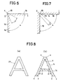
- a sharp, outwardly projecting joint edge 16 is formed at a convex corner portion (x) where two adjacent outer edge lines 15 defining an outside contour of the printing surface 14 meet or cross each other, the joint edge 16 being continuous with the edge lines 15.
- the joint edge 16 is composed of an outwardly tapered projection 17 which is formed integrally with the printing surface 14 at the convex corner portion (x).
- the angle of the joint edge 16 is adjusted to about 35 to 60 degrees, which is narrower than the angle a defined between the two edge lines 15.
- the projecting joint edge 16 includes two somewhat concavely curved edge line portions which extend outward and meet to form a pointed end.
- the shape and size of the joint edge 16 are identical with the desired ones which are determined in consideration of the arcuate isobaric lines (1) at the corner portion (a) as described with reference to Fig. 4.
- an inwardly extending joint edge 19 is formed at a concave corner portion (y) where two adjacent inner edge lines 18 defining an inside contour of the printing surface 14 meet or cross each other, the joint edge 19 being continuous with the edge lines 18.
- the joint edge 19 is composed of a notch 20 tapered toward the inner part of the printing surface 14.
- the notch 20 defined by the joint edge 19 is shaped like a smooth, continuous U-shaped cut, as shown in Fig. 7, in order to prevent lowering of the strength of dies used in forming the notch portion integrally with the printing surface 14, or lowering of the strength of the type due to undesirable effects of the notch 20.
- the shape and size of the notch 20 are determined in consideration of the isobaric lines (1) at the corner portion (b) as described with reference to Fig. 4.
- joint edges 16 and 19 constitute dull print edge canceling edge means.
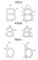
- Figs. 8(a), 9(a), 10(a), 11(a), 12 (a) and 13(a) are enlarged views showing the shapes of various characters 21 printed on printing paper by means of the types 10 of the invention representing various letters A, B, a, b, M and W, respectively.
- Figs. 8(b), 9(b), 10(b), 11(b), 12(b) and 13(b) are enlarged views showing the shapes of the printing surfaces 14 of the invention used to produce the printed characters 21.
- Figs. 8(b) to 13(b) are sectional views as taken along near-surface line I-I of Fig. 5, corresponding to the printing surfaces 14. The printing surfaces 14 shown in Figs.
- the joint edges 16 and 19 are not formed at concave corner portions (z) (Fig. 8(b)) and convex corner portions (f) (Figs. 10(b), 12(b) and 13(b)), for example, since the shape or quality of the printed characters at these portions is hardly influenced by dull print edges, if any, or that the angle between each two adjacent edge lines at the corner portions is an obtuse angle such that the effect of dull print edges is small.
- the concave joint edges 19 should preferably be provided to make the blank portions (k) clear-cut for improved print shape and quality.
- convex and concave joint edges 16 and 19 may be provided at desired convex and concave corner portions, respectively, of other characters, including letters, figures, etc., as well as those illustrative characters described in connection with the above-mentioned embodiment.
Landscapes
- Printing Plates And Materials Therefor (AREA)
- Printing Methods (AREA)
Applications Claiming Priority (2)
| Application Number | Priority Date | Filing Date | Title |
|---|---|---|---|
| JP24528384A JPS61121939A (ja) | 1984-11-19 | 1984-11-19 | 活字 |
| JP245283/84 | 1984-11-19 |
Publications (1)
| Publication Number | Publication Date |
|---|---|
| EP0182331A1 true EP0182331A1 (fr) | 1986-05-28 |
Family
ID=17131361
Family Applications (1)
| Application Number | Title | Priority Date | Filing Date |
|---|---|---|---|
| EP19850114611 Ceased EP0182331A1 (fr) | 1984-11-19 | 1985-11-17 | Type |
Country Status (2)
| Country | Link |
|---|---|
| EP (1) | EP0182331A1 (fr) |
| JP (1) | JPS61121939A (fr) |
Citations (1)
| Publication number | Priority date | Publication date | Assignee | Title |
|---|---|---|---|---|
| US3983814A (en) * | 1973-07-16 | 1976-10-05 | Baker Ray E | Reading type |
-
1984
- 1984-11-19 JP JP24528384A patent/JPS61121939A/ja active Pending
-
1985
- 1985-11-17 EP EP19850114611 patent/EP0182331A1/fr not_active Ceased
Patent Citations (1)
| Publication number | Priority date | Publication date | Assignee | Title |
|---|---|---|---|---|
| US3983814A (en) * | 1973-07-16 | 1976-10-05 | Baker Ray E | Reading type |
Also Published As
| Publication number | Publication date |
|---|---|
| JPS61121939A (ja) | 1986-06-09 |
Similar Documents
| Publication | Publication Date | Title |
|---|---|---|
| US4833627A (en) | Computerized typesetting correction system | |
| US3390631A (en) | Combined relief and intaglio printing method and machine | |
| EP0398267B1 (fr) | Plaque pour l'impression en creux | |
| EP0791473A3 (fr) | Encre d'enregistrement pour l'impression par jet d'encre contenant et procédé pour l'enregistrement | |
| ZA200301516B (en) | Data carrier comprising a gravure printed image and methods for transposing image motifs into linear structure and onto a gravure printing plate. | |
| EP0983855A3 (fr) | Substitution de points pour la compensation des buses à jet d'encre défaillantes | |
| EP1524121A3 (fr) | Impression avec réduction de bavures dans le contour | |
| EP0182331A1 (fr) | Type | |
| EP0936075A3 (fr) | Imprimante, méthode d'impression et programme d'ordinateur pour actualiser l'imprimante | |
| US3773160A (en) | Obliterating sign type carrier for typewriting or similar machines | |
| US3202257A (en) | Bold face type characters having recessed faces | |
| US935519A (en) | Type for type-writing and other machines. | |
| JPS57129760A (en) | Controlling method for rule-line printing in dot printer | |
| US624961A (en) | Tool for lightening and softening surfaces of printing-plates | |
| JPS6136364Y2 (fr) | ||
| JPH0512048Y2 (fr) | ||
| DE2836012C3 (de) | Vorrichtung zum Abdrucken von Typen auf einem Aufzeichnungsträger in Druckgeräten, insbesondere bei Daten- oder Fernschreibmaschinen | |
| JP2007062018A (ja) | スクリーン印刷機 | |
| JPH0215385B2 (fr) | ||
| US4093059A (en) | Character slug construction | |
| CN217293857U (zh) | 一种新型耐磨印版结构 | |
| US4852478A (en) | Apparatus for imprinting a document with secure, machine readable information | |
| US4134337A (en) | Concave impact print hammers | |
| CN214042837U (zh) | 骑缝锯齿防伪标识物 | |
| JPH0569529A (ja) | グラビア印刷法およびそれに用いる凹版 |
Legal Events
| Date | Code | Title | Description |
|---|---|---|---|
| PUAI | Public reference made under article 153(3) epc to a published international application that has entered the european phase |
Free format text: ORIGINAL CODE: 0009012 |
|
| AK | Designated contracting states |
Kind code of ref document: A1 Designated state(s): CH DE FR GB IT LI |
|
| 17P | Request for examination filed |
Effective date: 19861114 |
|
| 17Q | First examination report despatched |
Effective date: 19880205 |
|
| STAA | Information on the status of an ep patent application or granted ep patent |
Free format text: STATUS: THE APPLICATION HAS BEEN REFUSED |
|
| 18R | Application refused |
Effective date: 19881208 |
|
| RIN1 | Information on inventor provided before grant (corrected) |
Inventor name: INAZUKA, HIROJI |