EP0182384A1 - Dispositif pour empiler des articles plats, de préférence des sacs fabriqués à partir d'une feuille de matière plastique - Google Patents
Dispositif pour empiler des articles plats, de préférence des sacs fabriqués à partir d'une feuille de matière plastique Download PDFInfo
- Publication number
- EP0182384A1 EP0182384A1 EP85114853A EP85114853A EP0182384A1 EP 0182384 A1 EP0182384 A1 EP 0182384A1 EP 85114853 A EP85114853 A EP 85114853A EP 85114853 A EP85114853 A EP 85114853A EP 0182384 A1 EP0182384 A1 EP 0182384A1
- Authority
- EP
- European Patent Office
- Prior art keywords
- stacking
- frame
- end frame
- tools
- stack
- Prior art date
- Legal status (The legal status is an assumption and is not a legal conclusion. Google has not performed a legal analysis and makes no representation as to the accuracy of the status listed.)
- Granted
Links
- 238000004080 punching Methods 0.000 claims description 4
- 230000006978 adaptation Effects 0.000 abstract description 2
- 238000003466 welding Methods 0.000 description 2
- 229910000831 Steel Inorganic materials 0.000 description 1
- 230000000903 blocking effect Effects 0.000 description 1
- 239000011248 coating agent Substances 0.000 description 1
- 238000000576 coating method Methods 0.000 description 1
- 238000006073 displacement reaction Methods 0.000 description 1
- 238000000034 method Methods 0.000 description 1
- 239000010959 steel Substances 0.000 description 1
- 238000004804 winding Methods 0.000 description 1
Images


Classifications
-
- B—PERFORMING OPERATIONS; TRANSPORTING
- B31—MAKING ARTICLES OF PAPER, CARDBOARD OR MATERIAL WORKED IN A MANNER ANALOGOUS TO PAPER; WORKING PAPER, CARDBOARD OR MATERIAL WORKED IN A MANNER ANALOGOUS TO PAPER
- B31B—MAKING CONTAINERS OF PAPER, CARDBOARD OR MATERIAL WORKED IN A MANNER ANALOGOUS TO PAPER
- B31B70/00—Making flexible containers, e.g. envelopes or bags
-
- B—PERFORMING OPERATIONS; TRANSPORTING
- B31—MAKING ARTICLES OF PAPER, CARDBOARD OR MATERIAL WORKED IN A MANNER ANALOGOUS TO PAPER; WORKING PAPER, CARDBOARD OR MATERIAL WORKED IN A MANNER ANALOGOUS TO PAPER
- B31B—MAKING CONTAINERS OF PAPER, CARDBOARD OR MATERIAL WORKED IN A MANNER ANALOGOUS TO PAPER
- B31B70/00—Making flexible containers, e.g. envelopes or bags
- B31B70/74—Auxiliary operations
- B31B70/92—Delivering
- B31B70/98—Delivering in stacks or bundles
- B31B70/984—Stacking bags on wicket pins
-
- B—PERFORMING OPERATIONS; TRANSPORTING
- B31—MAKING ARTICLES OF PAPER, CARDBOARD OR MATERIAL WORKED IN A MANNER ANALOGOUS TO PAPER; WORKING PAPER, CARDBOARD OR MATERIAL WORKED IN A MANNER ANALOGOUS TO PAPER
- B31B—MAKING CONTAINERS OF PAPER, CARDBOARD OR MATERIAL WORKED IN A MANNER ANALOGOUS TO PAPER
- B31B2160/00—Shape of flexible containers
- B31B2160/10—Shape of flexible containers rectangular and flat, i.e. without structural provision for thickness of contents
-
- Y—GENERAL TAGGING OF NEW TECHNOLOGICAL DEVELOPMENTS; GENERAL TAGGING OF CROSS-SECTIONAL TECHNOLOGIES SPANNING OVER SEVERAL SECTIONS OF THE IPC; TECHNICAL SUBJECTS COVERED BY FORMER USPC CROSS-REFERENCE ART COLLECTIONS [XRACs] AND DIGESTS
- Y10—TECHNICAL SUBJECTS COVERED BY FORMER USPC
- Y10S—TECHNICAL SUBJECTS COVERED BY FORMER USPC CROSS-REFERENCE ART COLLECTIONS [XRACs] AND DIGESTS
- Y10S493/00—Manufacturing container or tube from paper; or other manufacturing from a sheet or web
- Y10S493/916—Pliable container
- Y10S493/926—Pliable container having handle or suspension means
Definitions
- the invention relates to a device for stacking flat objects, preferably provided with positioning holes, preferably bags which are looped away from a plastic tube or semi-tube web and which are preferably transferred from a so-called Vicketer with transport arms rotating in pairs, arranged in pairs, consisting of a stacking section Endless, intermittently driven traction means running over deflection wheels or rollers, which are provided with upstanding stacking pins or needles attached to support plates.
- the object of the invention is to provide a device of the type specified at the outset which, with simple adaptation to different formats and changing conditions, allows different types of processing on the stacks in a simple manner.
- this object is achieved in that two stacking sections are provided and in that different tools for processing the intermittently conveyed stacking are optionally interchangeable and arranged in a frame-fixed manner between the stacking sections.
- the arrangement of two stacking sections makes it possible to selectively arrange processing tools fixed to the frame between them, which can interact in any way, since it is no longer necessary to include the stacking plates which are moved intermittently as a counter-tool.
- the two stacking sections can be designed correspondingly lighter because they only serve for stacking and no longer have to take on the function of counter tools.
- the tools can consist of an abutment fixed to the frame in the region of the conveying plane, the length of which corresponds to the length of the stack in the conveying direction, and a heated, raised and lowered cutting knife of corresponding length, which is mounted in frame parts fixed to the frame.
- a heated, raised and lowered cutting knife of corresponding length which is mounted in frame parts fixed to the frame.
- double bags stacked on the stacking sections can be separated in the middle, the heated cutting knife simultaneously blocking the separated stacks on the cut surfaces.
- the cutting knife and the abutment can be exchanged or completely removed as required.
- the tools consist of an abutment plate fixed to the frame and of punching or holding punches and / or perforating knives which can be lowered thereon.
- an abutment plate preferably provided with holding stamps, offers the advantage that it can be provided with cutouts, so that processing tools can also be arranged below the abutment plate, which pass through the cutouts for processing the stack. For example, a heated cutting knife can thus pass through the abutment plate from below for severing the stacks.
- each stacking section which preferably consist of toothed belts, can also be provided with only one needle or a pin, so that after the stacks are separated by a longitudinal cut, the stack halves, which hang laterally over the stacking sections, rotate when the needle or the pin is arranged laterally, ie eccentrically. This rotation can be advantageous in order to move the cut surfaces away from the heated cutting knife.
- the longitudinal beams of the two stacking sections are in the end frame a transverse axis mounted non-rotatably about its horizontal axis and supported in its central or front area by a stamp or the like on a support connecting the end frame to the wicket frame, which is rigidly connected to the end frame and is guided with its front end on a transverse axis of the wicket frame , the end frame being guided displaceably or displaceably on floor-fixed guides in the transverse direction and a device for moving the end frame in the transverse direction is provided.
- both stacking sections are moved against each other.
- both stacking sections are moved laterally together, to the extent that the stacking sections enclose the winding arms on one side between them.
- the tool set does not need to be removed to operate the device with only one side stack, since it does not impair the stacking.
- the longitudinal members of the stacking sections are mounted on the transverse axis of the end frame via slide bushes connected in a rotationally fixed manner, and both longitudinal members are provided with threaded nuts with opposing threads into which a common transverse spindle axis is screwed for adjusting the distance between the stacking sections , and that the longitudinal beams of the stacking sections are supported on a slide plate carried by the stamp or the like.
- This configuration makes it possible to change the spacing of the stacking sections in a simple manner only by actuating the spindle in order to adapt to different formats.
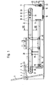
- a shaft 4 is provided which is provided with a drive (not shown) and which carries the transport arms 5 arranged in pairs and provided with suction devices or gripping devices.
- a cross-welding separating device Arranged in front of the winder frame 3 is a cross-welding separating device, not shown, for welding bags off a plastic tube or semi-tube web, from which the rotating transport arms 5 take over the finished bags or double bags and needle them onto the stacking pins b, 7 of the stacking sections 8, 9.
- the endless toothed belts carrying the stacking pins are moved intermittently by such a distance that a set of new stacking pins or needles is brought into the position in which the bags are removed from the transport arms.
- the side parts 11, 12 of the end frame 10 are connected to one another by a front cross member 13.
- a longitudinal member 14 is rigidly connected, which is provided at its front end with a bush 15, which on the a pipe or round steel existing transverse axis 16 of the wicket frame is guided to be displaceable.
- the transverse axis 16 is connected to the side parts 1, 2 of the winder frame 3 by holding pieces 17, 18.
- the end frame 10 has two rollers 19 in the region of its side parts 11, 12, which are guided in transverse floor-fixed guides.
- the side parts 11, 12 of the end frame 10 are also stiffened in their rear region by a cross member 20, which carries on its underside a transverse rack 21 with which the pinion 22 of the gear motor 23 fixed to the ground meshes.
- the end frame By actuating the geared motor 23, the end frame can be moved in the transverse direction on the rollers 19, the longitudinal member 14 being carried along and sliding over its front bush 15 on the transverse axis 16 of the winder frame 3 in accordance with the transverse displacement.
- the longitudinal beams 24 of the two stacking sections 8, 9 are fixedly connected in the region of the end frame 10 to transverse bushings 25, preferably ball bushings, which are displaceably guided on a transverse axis consisting of a tube 26 or the like, which is held in the side parts 11, 12 are.
- transverse bushings 25 preferably ball bushings, which are displaceably guided on a transverse axis consisting of a tube 26 or the like, which is held in the side parts 11, 12 are.
- the side members 24 of the two stacking sections 8, 9 are supported on a slide plate 28 which is carried by a stamp 29 which is fastened on the side member 14.
- the longitudinal beams 24 of the stack sections 8, 9 are provided at their front ends in a fork shape with bearing pieces 3U, between which the deflection wheels 31 are freely rotatable.
- the rear ends of the carrier 24 are also fork-shaped with bearing pieces 32, between which the drive wheels 33 are mounted.
- the longitudinal beams 24 of the two stacking sections are also provided with transverse threaded nuts 34 into which the opposite thread provided spindle 35 is screwed, which is rotatably mounted in the side parts 11, 12 of the end frame.
- the spindle 35 passes through the side part 12 and is provided with a handwheel 36, by means of which the distance between the stack sections 8, 9 can be adjusted.
- the freely projecting supports 24 of the two stacking sections slide on the plate 28 provided with a sliding coating.
- the lower longitudinal member 14, which connects the winder frame 1 to the end frame 10, is provided with lateral base frame parts 41, 42 which are connected to the latter via flanges 40 and which carry side parts 43, 44. These side parts arranged to the side of the stack sections 8, 9 serve to hold tools that process the stack.
- an abutment 45 is screwed onto the lower longitudinal member 14 and is provided with the bottom flanges 46, 47 receiving the screws.
- the top of the abutment 45 is provided with a sufficiently heat-resistant plastic strip 48 for padding.
- the top of this strip 48 lies in the region of the conveying plane of the stacking pins 50 carried by plates 49.
- the plates 49 carrying the stacking pins 50 are alternately connected to toothed belts 51, 52 which run in parallel and in pairs.
- the heated cutting knife 53 can be raised and lowered and cuts the stacks between the stacking pins 50.
- an abutment plate 55 fixed to the frame is provided, which is provided with a central recess 50.
- abutment plate 55 On the side parts 43, 44 lowerable holding punch 57 and perforating knife 58 are arranged.
- a heatable cutting knife 59 Arranged below the abutment plate is a heatable cutting knife 59 which can be raised and lowered and which extends through the recess 55. After the holding punches 57 have been lowered, a stack lying on the abutment plate 50 can thus be severed by lifting the lower knife 59.
- needles bl are fastened on the plates fastened to the toothed belt, onto which the bags can be needled by the support arms 5 without prior positioning holes.
Landscapes
- Making Paper Articles (AREA)
- Delivering By Means Of Belts And Rollers (AREA)
- Discharge By Other Means (AREA)
- Perforating, Stamping-Out Or Severing By Means Other Than Cutting (AREA)
Applications Claiming Priority (4)
| Application Number | Priority Date | Filing Date | Title |
|---|---|---|---|
| DE3442851 | 1984-11-23 | ||
| DE3442851 | 1984-11-23 | ||
| DE19853505858 DE3505858A1 (de) | 1984-11-23 | 1985-02-20 | Vorrichtung zum stapeln von flachen gegenstaenden, vorzugsweise beuteln aus kunststoffolie |
| DE3505858 | 1985-02-20 |
Publications (2)
| Publication Number | Publication Date |
|---|---|
| EP0182384A1 true EP0182384A1 (fr) | 1986-05-28 |
| EP0182384B1 EP0182384B1 (fr) | 1987-11-19 |
Family
ID=25826795
Family Applications (1)
| Application Number | Title | Priority Date | Filing Date |
|---|---|---|---|
| EP85114853A Expired EP0182384B1 (fr) | 1984-11-23 | 1985-11-22 | Dispositif pour empiler des articles plats, de préférence des sacs fabriqués à partir d'une feuille de matière plastique |
Country Status (7)
| Country | Link |
|---|---|
| US (1) | US4657528A (fr) |
| EP (1) | EP0182384B1 (fr) |
| JP (1) | JPH0698718B2 (fr) |
| CA (1) | CA1253179A (fr) |
| DE (1) | DE3505858A1 (fr) |
| DK (1) | DK158604C (fr) |
| ES (1) | ES8609029A1 (fr) |
Cited By (2)
| Publication number | Priority date | Publication date | Assignee | Title |
|---|---|---|---|---|
| EP0239857A3 (en) * | 1986-04-04 | 1988-10-19 | Windmoller & Holscher | Device for stacking flat objects, especially double bags made of a plastics film |
| EP0244600A3 (en) * | 1986-04-02 | 1988-10-19 | Windmoller & Holscher | Device for stacking flat objects, especially double bags made of a plastics film |
Families Citing this family (9)
| Publication number | Priority date | Publication date | Assignee | Title |
|---|---|---|---|---|
| DE3637491A1 (de) * | 1986-11-04 | 1988-05-19 | Windmoeller & Hoelscher | Verfahren und vorrichtung zum stapeln von flachen gegenstaenden vorzugsweise doppelbeuteln, aus kunststoffolie |
| US5000728A (en) * | 1987-06-12 | 1991-03-19 | Lemo M. Lehmacher & Sohn Gmbh Maschinenfabrik | Method of and apparatus for stacking bag segments |
| GB2223201B (en) * | 1988-09-30 | 1992-09-09 | Shen Dar Plastic Machinery Co | Apparatus for producing plastics carrier bags |
| DE3834115C1 (fr) * | 1988-10-07 | 1990-05-03 | Karl Heinz 7000 Stuttgart De Stiegler | |
| DE3838563A1 (de) * | 1988-11-14 | 1990-05-17 | Windmoeller & Hoelscher | Vorrichtung zum stapeln von flachen gegenstaenden |
| DE10059974A1 (de) * | 2000-12-02 | 2002-06-06 | Melitta Haushaltsprodukte | Verfahren zur Herstellung eines tütenartigen Filterpapiereinsatzes |
| JP4902796B1 (ja) * | 2011-03-30 | 2012-03-21 | トタニ技研工業株式会社 | 製袋機 |
| CN111483771B (zh) * | 2020-04-23 | 2021-11-02 | 临泉县曙光食品有限公司 | 一种适用于面粉的运输装置 |
| CN112224665A (zh) * | 2020-11-04 | 2021-01-15 | 王霞 | 一种电动车制造所需金属管用堆放架 |
Citations (2)
| Publication number | Priority date | Publication date | Assignee | Title |
|---|---|---|---|---|
| DE3138221A1 (de) * | 1980-09-26 | 1982-06-16 | Fmc Corp., Chicago, Ill. | Verfahren zur herstellung thermoplastischer beutel |
| DE3140021A1 (de) * | 1981-10-08 | 1983-04-28 | Hobema Maschinenfabrik Hermann H. Raths GmbH & Co KG, 4000 Düsseldorf | Einrichtung zur bildung und angabe von paeckchen aus mehreren, flaechigen einzelerzeugnissen aus papier, zellstoffwatte od. dgl. |
Family Cites Families (9)
| Publication number | Priority date | Publication date | Assignee | Title |
|---|---|---|---|---|
| GB1097478A (en) * | 1965-12-22 | 1968-01-03 | Charles Richard Stevens | Method and apparatus for girth wrapping rectangular blocks of material |
| GB1180569A (en) * | 1967-03-16 | 1970-02-04 | Simon Ltd Henry | Improvements in or relating to Bundling Machines |
| DE1900337B2 (de) * | 1969-01-04 | 1977-03-24 | Sengewald, Karl-Heinz, Dr., 4802 Halle | Verfahren zum herstellen von tragetaschen aus kunststoffolie |
| GB1317375A (en) * | 1971-03-31 | 1973-05-16 | Oestergaard G Vejle Plastic | Carrier bags |
| US4181069A (en) * | 1978-04-28 | 1980-01-01 | Chase Bag Company | Method for producing double streams of side-welded bags in heat-welded pad form |
| JPS5813339B2 (ja) * | 1979-08-31 | 1983-03-12 | 東洋食品機械株式会社 | 袋をピンに插入積み重ねる装置 |
| DE3020009A1 (de) * | 1980-05-24 | 1981-12-03 | Hans 5216 Niederkassel Lehmacher | Vorrichtung fuer die herstellung von beuteln aus einer kunststoffolien-schlauchbahn |
| DE8128146U1 (de) * | 1980-09-26 | 1982-12-09 | Fmc Corp., Chicago, Ill. | Vorrichtung zur herstellung von beutelstapeln |
| FR2521482A3 (fr) * | 1982-02-16 | 1983-08-19 | Moreau Andre Cie Ets | Procede et machine pour la realisation de sacs en films de matiere plastique ou similaire presentant une fenetre ouverte sur l'une de leurs faces |
-
1985
- 1985-02-20 DE DE19853505858 patent/DE3505858A1/de active Granted
- 1985-11-20 CA CA000495814A patent/CA1253179A/fr not_active Expired
- 1985-11-21 ES ES549167A patent/ES8609029A1/es not_active Expired
- 1985-11-21 DK DK539185A patent/DK158604C/da not_active IP Right Cessation
- 1985-11-22 EP EP85114853A patent/EP0182384B1/fr not_active Expired
- 1985-11-22 US US06/800,810 patent/US4657528A/en not_active Expired - Fee Related
- 1985-11-25 JP JP60264736A patent/JPH0698718B2/ja not_active Expired - Lifetime
Patent Citations (2)
| Publication number | Priority date | Publication date | Assignee | Title |
|---|---|---|---|---|
| DE3138221A1 (de) * | 1980-09-26 | 1982-06-16 | Fmc Corp., Chicago, Ill. | Verfahren zur herstellung thermoplastischer beutel |
| DE3140021A1 (de) * | 1981-10-08 | 1983-04-28 | Hobema Maschinenfabrik Hermann H. Raths GmbH & Co KG, 4000 Düsseldorf | Einrichtung zur bildung und angabe von paeckchen aus mehreren, flaechigen einzelerzeugnissen aus papier, zellstoffwatte od. dgl. |
Cited By (2)
| Publication number | Priority date | Publication date | Assignee | Title |
|---|---|---|---|---|
| EP0244600A3 (en) * | 1986-04-02 | 1988-10-19 | Windmoller & Holscher | Device for stacking flat objects, especially double bags made of a plastics film |
| EP0239857A3 (en) * | 1986-04-04 | 1988-10-19 | Windmoller & Holscher | Device for stacking flat objects, especially double bags made of a plastics film |
Also Published As
| Publication number | Publication date |
|---|---|
| JPH0698718B2 (ja) | 1994-12-07 |
| US4657528A (en) | 1987-04-14 |
| DK158604B (da) | 1990-06-18 |
| EP0182384B1 (fr) | 1987-11-19 |
| DK539185D0 (da) | 1985-11-21 |
| ES549167A0 (es) | 1986-07-16 |
| JPS61132327A (ja) | 1986-06-19 |
| DK539185A (da) | 1986-05-24 |
| DE3505858C2 (fr) | 1991-10-31 |
| DE3505858A1 (de) | 1986-06-05 |
| CA1253179A (fr) | 1989-04-25 |
| ES8609029A1 (es) | 1986-07-16 |
| DK158604C (da) | 1990-11-19 |
Similar Documents
| Publication | Publication Date | Title |
|---|---|---|
| DE68903016T2 (de) | Vorrichtung zum Verschliessen von Behältern mittels einer versiegelbaren Folie. | |
| EP0239857B1 (fr) | Dispositif pour empiler des objets plats, en particulier des sacs doubles en matière thermoplastique | |
| EP0182384B1 (fr) | Dispositif pour empiler des articles plats, de préférence des sacs fabriqués à partir d'une feuille de matière plastique | |
| EP0111210B1 (fr) | Dispositif d'enveloppement d'articles avec une feuille en matière plastique ou similaire | |
| DE2164279B2 (de) | Vorrichtung zum automatischen Aufrichten von Kartonagenzuschnitten | |
| DE3432385C2 (de) | Vorrichtung zum Stanzen von Stapeln aus flachen Werkstücken | |
| DE3812604A1 (de) | Vorrichtung zum herstellen von behaeltern | |
| DE2755625A1 (de) | Schneidvorrichtung | |
| DE1131979B (de) | Stapelvorrichtung fuer bogenfoermiges Material | |
| DE2708853A1 (de) | Vorrichtung zum durchtrennen und gleichzeitigem verblocken eines aus folienfoermigen abschnitten gebildeten stapels | |
| DE2005040C3 (de) | Schneidvorrichtung für eine Maschine zum Herstellen von Säcken aus einem Kunststoffschlauch | |
| DE3505109C1 (de) | Vorrichtung zum Stapeln von mit zwei Positionierloechern versehenen flachen Gegenstaenden,vorzugsweise Beuteln aus Kunststoffolie | |
| EP0294582A2 (fr) | Dispositif de fabrication de sachets ou de sacs à partir d'une gaine thermoplastique de préférence pourvue de plis latéraux | |
| DE3637491C2 (fr) | ||
| DE3531457C2 (fr) | ||
| DE1560107B2 (de) | Vorrichtung zum schneiden eines stapels von bahnen aus papier, zellulose oder dergleichen | |
| EP0135734B1 (fr) | Procédé et dispositif pour supprimer le blocage de tas de sacs estampés | |
| EP0920984B1 (fr) | Appareil pour la fabrication de sacs à poignées en feuilles de matière thermoplastique | |
| EP0182343B1 (fr) | Dispositif pour aligner une station d'empilage dite à tourniquet avec un bord de trajectoire | |
| DE369441C (de) | Glasschneidemaschine fuer Glastafeln | |
| DE2733626A1 (de) | Schneideinrichtung fuer verpackungsmaschinen | |
| DE2509697C2 (de) | Vorrichtung zum seitlichen, quer zur Förderrichtung erfolgenden Vereinzeln von nebeneinanderliegend auf einer Fördereinrichtung vorgeschobenen heftförmigen Gegenständen | |
| EP0341506B1 (fr) | Dispositif pour perforer des tubes en papier | |
| DE102022125320A1 (de) | Vorrichtung zum Trennen zumindest eines insbesondere geförderten Flächenelementes, insbesondere einer Kunststofffolie oder eines Kunststofffolienverbundmaterials in einzelne Bestandteile | |
| DE3316981C2 (fr) |
Legal Events
| Date | Code | Title | Description |
|---|---|---|---|
| PUAI | Public reference made under article 153(3) epc to a published international application that has entered the european phase |
Free format text: ORIGINAL CODE: 0009012 |
|
| AK | Designated contracting states |
Kind code of ref document: A1 Designated state(s): BE FR GB IT |
|
| 17P | Request for examination filed |
Effective date: 19860703 |
|
| 17Q | First examination report despatched |
Effective date: 19870205 |
|
| GRAA | (expected) grant |
Free format text: ORIGINAL CODE: 0009210 |
|
| AK | Designated contracting states |
Kind code of ref document: B1 Designated state(s): BE FR GB IT |
|
| ET | Fr: translation filed | ||
| ITF | It: translation for a ep patent filed | ||
| GBT | Gb: translation of ep patent filed (gb section 77(6)(a)/1977) | ||
| PLBE | No opposition filed within time limit |
Free format text: ORIGINAL CODE: 0009261 |
|
| STAA | Information on the status of an ep patent application or granted ep patent |
Free format text: STATUS: NO OPPOSITION FILED WITHIN TIME LIMIT |
|
| 26N | No opposition filed | ||
| ITTA | It: last paid annual fee | ||
| PGFP | Annual fee paid to national office [announced via postgrant information from national office to epo] |
Ref country code: GB Payment date: 19931021 Year of fee payment: 9 |
|
| PGFP | Annual fee paid to national office [announced via postgrant information from national office to epo] |
Ref country code: FR Payment date: 19931108 Year of fee payment: 9 |
|
| PGFP | Annual fee paid to national office [announced via postgrant information from national office to epo] |
Ref country code: BE Payment date: 19931118 Year of fee payment: 9 |
|
| PG25 | Lapsed in a contracting state [announced via postgrant information from national office to epo] |
Ref country code: GB Effective date: 19941122 |
|
| PG25 | Lapsed in a contracting state [announced via postgrant information from national office to epo] |
Ref country code: BE Effective date: 19941130 |
|
| BERE | Be: lapsed |
Owner name: WINDMOLLER & HOLSCHER Effective date: 19941130 |
|
| GBPC | Gb: european patent ceased through non-payment of renewal fee |
Effective date: 19941122 |
|
| PG25 | Lapsed in a contracting state [announced via postgrant information from national office to epo] |
Ref country code: FR Effective date: 19950731 |
|
| REG | Reference to a national code |
Ref country code: FR Ref legal event code: ST |