EP0182423B1 - Appareil et procédé de traitement des images à radiation - Google Patents
Appareil et procédé de traitement des images à radiation Download PDFInfo
- Publication number
- EP0182423B1 EP0182423B1 EP85201811A EP85201811A EP0182423B1 EP 0182423 B1 EP0182423 B1 EP 0182423B1 EP 85201811 A EP85201811 A EP 85201811A EP 85201811 A EP85201811 A EP 85201811A EP 0182423 B1 EP0182423 B1 EP 0182423B1
- Authority
- EP
- European Patent Office
- Prior art keywords
- image
- signal
- image processing
- mask
- digital signals
- Prior art date
- Legal status (The legal status is an assumption and is not a legal conclusion. Google has not performed a legal analysis and makes no representation as to the accuracy of the status listed.)
- Expired
Links
- 230000005855 radiation Effects 0.000 title claims description 15
- 238000000034 method Methods 0.000 title description 20
- 238000003672 processing method Methods 0.000 claims description 12
- OAICVXFJPJFONN-UHFFFAOYSA-N Phosphorus Chemical compound [P] OAICVXFJPJFONN-UHFFFAOYSA-N 0.000 claims description 7
- 238000006243 chemical reaction Methods 0.000 claims description 2
- 230000001186 cumulative effect Effects 0.000 claims 4
- 230000004936 stimulating effect Effects 0.000 claims 2
- 238000003745 diagnosis Methods 0.000 description 5
- 230000006870 function Effects 0.000 description 4
- 210000000988 bone and bone Anatomy 0.000 description 3
- 230000000873 masking effect Effects 0.000 description 3
- 230000001360 synchronised effect Effects 0.000 description 3
- 210000004204 blood vessel Anatomy 0.000 description 2
- 241000282326 Felis catus Species 0.000 description 1
- 230000003247 decreasing effect Effects 0.000 description 1
- 238000010586 diagram Methods 0.000 description 1
- 230000000694 effects Effects 0.000 description 1
- 210000004072 lung Anatomy 0.000 description 1
- 239000000463 material Substances 0.000 description 1
- 210000002784 stomach Anatomy 0.000 description 1
- 239000012780 transparent material Substances 0.000 description 1
- 230000000007 visual effect Effects 0.000 description 1
Images


Classifications
-
- H—ELECTRICITY
- H04—ELECTRIC COMMUNICATION TECHNIQUE
- H04N—PICTORIAL COMMUNICATION, e.g. TELEVISION
- H04N1/00—Scanning, transmission or reproduction of documents or the like, e.g. facsimile transmission; Details thereof
- H04N1/40—Picture signal circuits
- H04N1/409—Edge or detail enhancement; Noise or error suppression
Definitions
- This invention relates to an image processing method and apparatus therefor, and more particularly to a method of and apparatus for conducting an unsharp masking process on an image on a radiographic film (hereinafter referred to as "X-ray image") to improve the diagnostic accuracy when the X-ray image is duplicated, and further to a method of and apparatus for frequency processing an image in a system for recording and reproducing a radiation image by use of stimulable phosphor sheet.
- X-ray image an unsharp masking process on an image on a radiographic film
- the principal object of the present invention is to provide a method of image processing an X-ray image or a radiation image in which the frequency emphasis is conducted without making a ghost image caused by overshoot or undershoot.
- Another object of the present invention is to provide an apparatus for image processing an X-ray image or radiation image by emphasizing a particular frequency component without making a ghost image caused by overshoot or undershoot.
- the method and apparatus for carrying out the frequency emphasis according to the present invention is characterized in that, in contrast to said prior art frequency emphasis in which the unsharp mask density or signal (Dus, Sus) was given based on an average of the image signals of all the picture cells in the unsharp mask, the unsharp mask density or signal is determined based on the median (central value) of the signals of the picture cells or elements the "median" (the (N2+1)/2-th, data in the accumulated histogram when N is an odd number, the N2/2-th or N2/2+1-th data in the accumulated histogram, when N is an even number) is adopted as the unsharp mask density or signal (Dus, Sus).
- the unsharp mask density or signal is determined based on the median (central value) of the signals of the picture cells or elements the "median" (the (N2+1)/2-th, data in the accumulated histogram when N is an odd number, the N2/2-th or N2/2+1-th data in the accumulated hist
- the median is employed as the unsharp mask signal, it becomes possible to limit the size of the object which is emphasized to those having a size smaller than a half of the size of the unsharp mask and occurrence of overshoot and undershoot is prevented and the ghost image can be eliminated.
- the edges of the large-sized structures such as ribs and the heart are not emphasized but only the blood vessels are emphasized. Accordingly, this method is particularly suitable for extracting blood vessel shadows of an image of lungs and provides an image of high diagnostic efficiency and accuracy. Further, it is suitable for extracting stomach walls or fine structures of bones. Hence, the diagnostic efficiency and accuracy can be fairly improved in the filed of medical diagnosis. Furthermore, since the ghost images are prevented from being formed in the radiation images, the shape of the edges of bones can be correctly reproduced, which will prevent errors in diagnosis and is therefore very desirable in the medical diagnostic application.
- FIG. 2 shows an embodiment of an apparatus for carrying out the method of image processing according to the present invention.
- a radiographic film 1 bearing X-ray image information is attached on the surface of a rotating drum 3 made of transparent material, and the light from a light source 2 located in the drum 3 passing through the radiographic film 1 is received by a photomultiplier tube 4 located outside the drum 3 to convert the image information into an electric signal.
- the electric image signal is converted to digital values by way of a logarithmic amplifier 4' and an A/D converter 5 to obtain digital values of original density Dorg.
- the X-ray image information is digitized by use of a drum scanner in the above-described example. However, it may be understood that a plan scanner using a CCD line sensor can be employed instead.
- the image signal indicative of the original density Dorg thus obtained or the signal taken out of a memory device 6 which memorizes the original density signal Dorg thus obtained in a magnetic tape or disc is input into a median calculating unit 7.
- a median (Dus) of the image signal or digital data of the picture elements in an unsharp mask having the size of N x N is calculated, and the calculated median Dus and the original density signal Dorg are input into an arithmetic unit 8.
- an operation of Dorg + ⁇ (Dorg - Dus) i.e. frequency processing, is conducted to output a final image density D which is frequency processed.
- the above operation may be conducted by use of a multiprocessor in which synchronization is made for every line or as shown in Figure 3 by non-synchronized calculation of median calculation and frequency processing calculation. That is, as shown in Figure 3, it is possible to input an image density Dorg into an image memory 10, and calculate the median and the frequency processing in a non-synchronized manner in a median calculating unit 7' and a frequency processing calculating unit 8' based on the digital data stored in the image memory 10, which has as its output a final image signal indicating the final image density D from the image memory 10.
- the calculation according to the example as shown in Figure 3 is disadvantageous in that it is not a real time processing but is advantageous in that it is possible to output an image only based on the median. Further, it is of course possible to make the calculation in the median calculating unit 7' and the calculation in the frequency processing unit 8' synchronized with each other by use of a single processor.
- the output image signal is forwarded to a recording device or a reproducing device to record or reproduce an image. That is, the output signal may be recorded in a magnetic tape or disc to be stored or used for reproducing a visible image on a cat of a photosensitive material.
- Figure 4A shows the original image data Dorg.
- the width of the object of the image is indicated by L in Figure 4A, whereas the width of the unsharp mask is N picture elements.
- Figure 4A' shows the accumulated histogram for the picture elements within the mask for a position of the mask as is shown in Figure 4A.
- L picture elements having a high signal value Q
- N-L picture elements having a low signal value R. From Figure 4A' it follows that the median is the signal value corresponding with 1/2 N picture elements.
- the unsharp mask signal (Dus) will become the same as the original image signal (Dorg) as shown in Figure 4D. Therefore, the final signal after the frequency signal (D) will become the same as the original signal (Dorg) as shown in Figure 4E. That is, in this case, the structure or object of a comparatively large size cannot be employed. In this case too, no overshoot or undershoot is observed.
- the influence thereof can mostly be eliminated by using an emphasizing function F(Dorg) in place of the emphasizing coefficient ⁇ as shown in Figure 7. That is, since the X-ray quantum noise mainly observed in an X-ray image often appear in the low density area of the image or the low exposure area, the noise can be eliminated by using a non-linear emphasizing function which reduces the emphasizing coefficient in the low density area.
- the emphasizing coefficient ⁇ can be a variable which varies according to the level of the original density Dorg. It should be noted, therefore, that the emphasizing coefficient may be a constant or a variable in this specification.
- the unsharp mask density or median Dus is obtained.
- the above-mentioned 8 bits may be 10 bits, in which case 255 becomes 1023, or more bits.
- the shape of the mask may not be a square but may be rectangular, M x N or may be a circle of the diameter R.
- Figures 8A, 8B and 8C show some of these examples in which not all of the image data in the mask is used for obtaining the median.
- Figure 8A shows a pattern of a cross
- Figure 8B shows a pattern of "X”
- Figure 8C shows a pattern of a combination of the cross and "X".
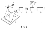
- Figure 9 shows another embodiment of the present invention which is applied to a radiation image recording and reproducing system using a stimulable phosphor sheet.
- a stimulable phosphor sheet 11 in which radiation image information is stored is scanned by a laser beam 12A emitted by a laser source 12 and deflected in the main scanning direction by a galvanometer 13.
- the scanned stimulable phosphor sheet 11 emits light upon exposure to the laser beam 12 A which is received by a photodetector 15 such as a photomultiplier tube by way of a light guide 14.
- the photodetector 15 converts the light carrying the radiation image information into an electric image signal Sorg.
- the output signal Sorg is forwarded to a logarithmic amplifier 16, then to an A/D converter 17, and further to a median calculating unit 18.
- the arithmetic unit 19 and a memory device 20 are equivalent to those as shown in Figure 2 as well as said elements 16 to 18.
Landscapes
- Engineering & Computer Science (AREA)
- Multimedia (AREA)
- Signal Processing (AREA)
- Image Processing (AREA)
- Image Analysis (AREA)
Claims (8)
- Procédé de traitement d'images pour balayer un dispositif de stockage d'information en vue d'en obtenir un signal d'image électrique et pour convertir le signal d'image électrique en une image visible, ce procédé de traitement d'images comprenant les étapes consistant à : convertir le signal d'image électrique en un certain nombre de signaux numériques (Dorg) pour des éléments d'image respectifs de l'image correspondant à des points de balayage et obtenir un signal de basse fréquence (Dus) pour chaque élément d'image d'un groupe des signaux numériques dans un masque d'une dimension prédéterminée, et effectuer une opération Dorg + β(Dorg - Dus) en utilisant un coefficient d'accentuation de fréquence β, caractérisé en ce que, pour le signal de basse fréquence Dus, on utilise une valeur de signal pour laquelle, dans une distribution cumulative (histogramme accumulé) des signaux des éléments d'image dans le masque, on trouve la moitié des éléments d'image, c'est-à-dire la médiane du groupe de signaux numériques dans la distribution cumulative.
- Procédé de traitement d'images suivant la revendication 1, dans lequel la dimension du masque est rendue égale à plus du double de celle de l'objet que l'on souhaite accentuer dans l'image.
- Procédé de traitement d'images suivant la revendication 1 ou 2, dans lequel la médiane est déterminée pour certains des signaux numériques dans le masque.
- Procédé de traitement d'images suivant la revendication 3, dans lequel la médiane est déterminée pour des signaux numériques pour lesquels les éléments d'image dans le masque sont disposés en un motif d'une croix ou d'un "X" ou d'une combinaison d'une croix et d'un "X".
- Procédé de traitement d'images suivant la revendication 1, 2, 3 ou 4, dans lequel le dispositif de stockage d'information d'image (1) comprend un film à rayons X qui doit être balayé par un faisceau lumineux, ce faisceau lumineux, après le balayage du film à rayons X, portant l'information d'image et étant converti par un transducteur photoélectrique (4) en un signal électrique.
- Procédé de traitement d'images suivant la revendication 1, 2, 3 ou 4, dans lequel le dispositif de stockage d'information d'image comprend une feuille luminescente stimulable (11) qui est stimulée lors du balayage et émet de l'information d'image qui y est stockée, sous forme de lumière, le faisceau lumineux étant converti en un signal électrique.
- Appareil de traitement d'images de rayonnement pour un système d'enregistrement et de reproduction d'information d'images de rayonnement qui comprend une source de rayonnement de stimulation (12) pour émettre des rayons de stimulation de balayage qui balaient une feuille luminescente stimulable (11) portant de l'information d'image de rayonnement et qui provoquent l'émission, par la feuille luminescente stimulable (11), de lumière véhiculant l'information d'image de rayonnement, un photodétecteur (15) pour détecter la lumière émise et la convertir en un signal d'image électrique et des moyens actifs (16, 17, 18, 19, 20) pour traiter le signal d'image électrique, les moyens actifs comprenant : un convertisseur (17) pour convertir le signal d'image électrique en un certain nombre de signaux numériques (Sorg) pour des éléments d'image respectifs de l'image, un moyen actif (19) pour effectuer une opération

- Appareil de traitement d'image de rayonnement suivant la revendication 7, dans lequel le premier moyen actif (19) et le second moyen actif (18) sont formés par un processeur unique.
Applications Claiming Priority (4)
| Application Number | Priority Date | Filing Date | Title |
|---|---|---|---|
| JP240361/84 | 1984-11-14 | ||
| JP59240362A JP2542183B2 (ja) | 1984-11-14 | 1984-11-14 | X線画像処理方法および装置 |
| JP59240361A JPH069378B2 (ja) | 1984-11-14 | 1984-11-14 | 放射線画像処理方法および装置 |
| JP240362/84 | 1984-11-14 |
Publications (3)
| Publication Number | Publication Date |
|---|---|
| EP0182423A2 EP0182423A2 (fr) | 1986-05-28 |
| EP0182423A3 EP0182423A3 (en) | 1987-08-19 |
| EP0182423B1 true EP0182423B1 (fr) | 1992-08-26 |
Family
ID=26534697
Family Applications (1)
| Application Number | Title | Priority Date | Filing Date |
|---|---|---|---|
| EP85201811A Expired EP0182423B1 (fr) | 1984-11-14 | 1985-11-08 | Appareil et procédé de traitement des images à radiation |
Country Status (3)
| Country | Link |
|---|---|
| US (1) | US4747052A (fr) |
| EP (1) | EP0182423B1 (fr) |
| DE (1) | DE3586559T2 (fr) |
Families Citing this family (37)
| Publication number | Priority date | Publication date | Assignee | Title |
|---|---|---|---|---|
| CA1316591C (fr) * | 1987-10-20 | 1993-04-20 | Kazuhiro Hishinuma | Methode et appareil de traitement de photographies et de radiographies |
| US4908876A (en) * | 1988-03-16 | 1990-03-13 | Digivision, Inc. | Apparatus and method for enhancement of image viewing by modulated illumination of a transparency |
| JP2952418B2 (ja) * | 1988-09-16 | 1999-09-27 | 富士写真フイルム株式会社 | 放射線画像信号生成方法 |
| US5485534A (en) * | 1990-03-28 | 1996-01-16 | Fuji Photo Film Co., Ltd. | Method and apparatus for emphasizing sharpness of image by detecting the edge portions of the image |
| JP3003799B2 (ja) * | 1990-03-28 | 2000-01-31 | 富士写真フイルム株式会社 | 画像の鮮鋭度強調方法及びその装置 |
| JP2574923B2 (ja) * | 1990-04-10 | 1997-01-22 | 大日本スクリーン製造株式会社 | 輪郭強調方法および画像処理装置 |
| JP3039879B2 (ja) * | 1991-04-17 | 2000-05-08 | 富士写真フイルム株式会社 | 放射線画像の周波数処理方法 |
| US5524162A (en) * | 1991-07-22 | 1996-06-04 | Levien; Raphael L. | Method and apparatus for adaptive sharpening of images |
| EP0527524B1 (fr) * | 1991-08-13 | 1998-06-03 | Agfa-Gevaert N.V. | Procédé pour l'amélioration de la qualité d'une image |
| US6146817A (en) * | 1991-12-06 | 2000-11-14 | Agfa-Gevaert Aktiengesellschaft | Method of and apparatus for masking a master for reproduction |
| US6434262B2 (en) * | 1993-09-29 | 2002-08-13 | Shih-Ping Wang | Computer-aided diagnosis system and method |
| DE4404047C1 (de) * | 1994-02-09 | 1995-08-31 | Daimler Benz Aerospace Ag | Verfahren zur Beeinflussung der Bildqualität von durch eine elektronische Bildaufnahmevorrichtung gelieferten Bildern |
| JPH07248557A (ja) * | 1994-03-10 | 1995-09-26 | Konica Corp | 放射線画像の処理方法 |
| US5774599A (en) * | 1995-03-14 | 1998-06-30 | Eastman Kodak Company | Method for precompensation of digital images for enhanced presentation on digital displays with limited capabilities |
| JPH09107479A (ja) * | 1995-09-29 | 1997-04-22 | Fuji Photo Film Co Ltd | 画像処理方法および装置 |
| JP3669455B2 (ja) * | 1996-03-15 | 2005-07-06 | 富士写真フイルム株式会社 | 画像処理方法および画像処理装置 |
| US6424730B1 (en) | 1998-11-03 | 2002-07-23 | Eastman Kodak Company | Medical image enhancement method for hardcopy prints |
| US6822658B1 (en) | 1999-10-25 | 2004-11-23 | Intel Corporation | Rendering a silhouette edge |
| US6798411B1 (en) * | 1999-10-29 | 2004-09-28 | Intel Corporation | Image processing |
| US7180523B1 (en) | 2000-03-31 | 2007-02-20 | Intel Corporation | Trimming surfaces |
| JP2002116516A (ja) * | 2000-10-05 | 2002-04-19 | Fuji Photo Film Co Ltd | 放射線画像情報読取装置 |
| US7061501B1 (en) | 2000-11-07 | 2006-06-13 | Intel Corporation | Rendering a pencil-sketch image |
| US7116330B2 (en) | 2001-02-28 | 2006-10-03 | Intel Corporation | Approximating motion using a three-dimensional model |
| US7190374B2 (en) | 2001-02-28 | 2007-03-13 | Intel Corporation | Shading polygons from a three-dimensional model |
| US6980206B2 (en) * | 2001-06-07 | 2005-12-27 | Intel Corporation | Rendering a three-dimensional model using a dither pattern |
| US6924804B2 (en) * | 2001-09-25 | 2005-08-02 | Intel Corporation | Reducing the resolution of bones in a three-dimensional model |
| US6906724B2 (en) * | 2001-10-17 | 2005-06-14 | Lntel Corporation | Generating a shadow for a three-dimensional model |
| US7548241B2 (en) | 2002-01-04 | 2009-06-16 | Intel Corporation | Determining a node path through a node graph |
| US7301547B2 (en) | 2002-03-22 | 2007-11-27 | Intel Corporation | Augmented reality system |
| US7146297B2 (en) * | 2002-03-27 | 2006-12-05 | Intel Corporation | Detecting collisions of three-dimensional models |
| US6975318B2 (en) * | 2002-06-25 | 2005-12-13 | Intel Corporation | Polygon binning process for tile-based rendering |
| JP2004030366A (ja) * | 2002-06-27 | 2004-01-29 | Sharp Corp | フィルタ装置、データ駆動型情報処理装置、フィルタ方法、フィルタプログラムおよびフィルタプログラムを記録した機械読取り可能な記録媒体 |
| US6982715B2 (en) * | 2002-07-26 | 2006-01-03 | Intel Corporation | Mesh compression process |
| US7228004B2 (en) * | 2002-09-05 | 2007-06-05 | Eastman Kodak Company | Method for sharpening a digital image |
| US7953260B2 (en) * | 2006-06-09 | 2011-05-31 | Craniosim Solutions, Inc. | Predicting movement of soft tissue of the face in response to movement of underlying bone |
| US11127106B2 (en) | 2019-06-28 | 2021-09-21 | Intel Corporation | Runtime flip stability characterization |
| US11409341B2 (en) | 2019-10-01 | 2022-08-09 | Intel Corporation | Repeating graphics render pattern detection |
Family Cites Families (5)
| Publication number | Priority date | Publication date | Assignee | Title |
|---|---|---|---|---|
| FR2445536B1 (fr) * | 1978-12-26 | 1989-12-22 | Fuji Photo Film Co Ltd | Procede et appareil pour traiter une image radiographique |
| US4315318A (en) * | 1978-12-26 | 1982-02-09 | Fuji Photo Film Co., Ltd. | Method and apparatus for processing a radiation image |
| US4394737A (en) * | 1979-07-11 | 1983-07-19 | Fuji Photo Film Co., Ltd. | Method of processing radiographic image |
| JPS5691735A (en) * | 1979-12-25 | 1981-07-24 | Fuji Photo Film Co Ltd | Method and apparatus for treating xxray image |
| JPS56104645A (en) * | 1979-12-25 | 1981-08-20 | Fuji Photo Film Co Ltd | Radiation picture treating method and its device |
-
1985
- 1985-10-28 US US06/791,678 patent/US4747052A/en not_active Expired - Fee Related
- 1985-11-08 EP EP85201811A patent/EP0182423B1/fr not_active Expired
- 1985-11-08 DE DE8585201811T patent/DE3586559T2/de not_active Expired - Fee Related
Also Published As
| Publication number | Publication date |
|---|---|
| DE3586559T2 (de) | 1993-03-25 |
| EP0182423A2 (fr) | 1986-05-28 |
| US4747052A (en) | 1988-05-24 |
| EP0182423A3 (en) | 1987-08-19 |
| DE3586559D1 (de) | 1992-10-01 |
Similar Documents
| Publication | Publication Date | Title |
|---|---|---|
| US4747052A (en) | Radiation image processing | |
| EP0170270B1 (fr) | Méthode pour l'ajustage des conditions de sortie de mémoire d'une image de rayonnement | |
| EP0032237B1 (fr) | Procédé et appareil pour traiter une image radiographique | |
| EP0392504B1 (fr) | Procédé de génération de signaux d'images à radiation | |
| EP0440166A2 (fr) | Méthode de compression de gammes dynamiques d'images | |
| US5402338A (en) | Method for forming energy subtraction images | |
| US5485371A (en) | Method for forming energy subtraction radiation images, and method and apparatus for smoothing radiation images | |
| JP3538244B2 (ja) | ラジオグラフィー像の表示において飽和画素を捜し出す方法 | |
| JP2849964B2 (ja) | 画像処理方法および装置 | |
| EP0455986A2 (fr) | Méthode et appareil de traitement d'image de rayonnement par soustraction d'énergie | |
| US7433537B2 (en) | Image reproduction system for removing noise of a periodic pattern | |
| EP0758179A2 (fr) | Procédé et dispositif pour l'interpolation de signaux d'images | |
| US4306290A (en) | Image gradation processing method and apparatus for radiographic image copying system | |
| US5015854A (en) | Radiation image displaying apparatus | |
| US5231574A (en) | Method for detecting artifact signal components | |
| JP2598636B2 (ja) | 画像処理条件決定方法 | |
| EP0792061B1 (fr) | Procédé pour générer les signaux d'image de radiation et appareil pour lire la radiation | |
| US4992664A (en) | Radiation image read-out, processing and reproducing methods | |
| EP0546600B1 (fr) | Méthode pour déterminer la gamme des signaux d'image approprié à sa reproduction | |
| US5237176A (en) | Method of energy subtraction for radiation image and apparatus for carrying out the method | |
| US4806759A (en) | Method of adjusting radiation image read-out conditions | |
| EP0254301B1 (fr) | Méthode d'ajustement des conditions de traitement d'images de radiation | |
| EP0287102B1 (fr) | Méthode pour la détection de bruit dans des signaux d'image | |
| US5231575A (en) | Image read-out apparatus | |
| JP3181125B2 (ja) | 再生に関連がある信号レンジの決定方法 |
Legal Events
| Date | Code | Title | Description |
|---|---|---|---|
| PUAI | Public reference made under article 153(3) epc to a published international application that has entered the european phase |
Free format text: ORIGINAL CODE: 0009012 |
|
| AK | Designated contracting states |
Kind code of ref document: A2 Designated state(s): DE FR GB |
|
| PUAL | Search report despatched |
Free format text: ORIGINAL CODE: 0009013 |
|
| AK | Designated contracting states |
Kind code of ref document: A3 Designated state(s): DE FR GB |
|
| 17P | Request for examination filed |
Effective date: 19880218 |
|
| 17Q | First examination report despatched |
Effective date: 19880516 |
|
| GRAA | (expected) grant |
Free format text: ORIGINAL CODE: 0009210 |
|
| AK | Designated contracting states |
Kind code of ref document: B1 Designated state(s): DE FR GB |
|
| REF | Corresponds to: |
Ref document number: 3586559 Country of ref document: DE Date of ref document: 19921001 |
|
| ET | Fr: translation filed | ||
| REG | Reference to a national code |
Ref country code: FR Ref legal event code: CD |
|
| PLBE | No opposition filed within time limit |
Free format text: ORIGINAL CODE: 0009261 |
|
| STAA | Information on the status of an ep patent application or granted ep patent |
Free format text: STATUS: NO OPPOSITION FILED WITHIN TIME LIMIT |
|
| 26N | No opposition filed | ||
| REG | Reference to a national code |
Ref country code: FR Ref legal event code: CD |
|
| PGFP | Annual fee paid to national office [announced via postgrant information from national office to epo] |
Ref country code: FR Payment date: 19981117 Year of fee payment: 14 |
|
| PGFP | Annual fee paid to national office [announced via postgrant information from national office to epo] |
Ref country code: GB Payment date: 19981123 Year of fee payment: 14 |
|
| PGFP | Annual fee paid to national office [announced via postgrant information from national office to epo] |
Ref country code: DE Payment date: 19990125 Year of fee payment: 14 |
|
| PG25 | Lapsed in a contracting state [announced via postgrant information from national office to epo] |
Ref country code: GB Free format text: LAPSE BECAUSE OF NON-PAYMENT OF DUE FEES Effective date: 19991108 |
|
| GBPC | Gb: european patent ceased through non-payment of renewal fee |
Effective date: 19991108 |
|
| PG25 | Lapsed in a contracting state [announced via postgrant information from national office to epo] |
Ref country code: FR Free format text: LAPSE BECAUSE OF NON-PAYMENT OF DUE FEES Effective date: 20000731 |
|
| PG25 | Lapsed in a contracting state [announced via postgrant information from national office to epo] |
Ref country code: DE Free format text: LAPSE BECAUSE OF NON-PAYMENT OF DUE FEES Effective date: 20000901 |
|
| REG | Reference to a national code |
Ref country code: FR Ref legal event code: ST |
|
| APAH | Appeal reference modified |
Free format text: ORIGINAL CODE: EPIDOSCREFNO |