EP0182443A2 - Système lithographique à rayons X, en particulier sa régulation gazeuse ainsi que procédé de fabrication d'un substrat semi-conducteur - Google Patents
Système lithographique à rayons X, en particulier sa régulation gazeuse ainsi que procédé de fabrication d'un substrat semi-conducteur Download PDFInfo
- Publication number
- EP0182443A2 EP0182443A2 EP85201909A EP85201909A EP0182443A2 EP 0182443 A2 EP0182443 A2 EP 0182443A2 EP 85201909 A EP85201909 A EP 85201909A EP 85201909 A EP85201909 A EP 85201909A EP 0182443 A2 EP0182443 A2 EP 0182443A2
- Authority
- EP
- European Patent Office
- Prior art keywords
- mask
- gas
- chamber
- zone
- substrate
- Prior art date
- Legal status (The legal status is an assumption and is not a legal conclusion. Google has not performed a legal analysis and makes no representation as to the accuracy of the status listed.)
- Withdrawn
Links
- 238000000034 method Methods 0.000 title claims abstract description 38
- 239000000758 substrate Substances 0.000 title claims abstract description 21
- 239000004065 semiconductor Substances 0.000 title claims abstract description 6
- 239000007789 gas Substances 0.000 claims abstract description 83
- 239000012528 membrane Substances 0.000 claims abstract description 44
- 239000001307 helium Substances 0.000 claims abstract description 41
- 229910052734 helium Inorganic materials 0.000 claims abstract description 41
- SWQJXJOGLNCZEY-UHFFFAOYSA-N helium atom Chemical compound [He] SWQJXJOGLNCZEY-UHFFFAOYSA-N 0.000 claims abstract description 41
- 230000008569 process Effects 0.000 claims abstract description 29
- 238000004519 manufacturing process Methods 0.000 claims abstract description 10
- 238000013022 venting Methods 0.000 claims description 8
- 238000009792 diffusion process Methods 0.000 claims description 6
- 230000005540 biological transmission Effects 0.000 claims description 5
- 239000000463 material Substances 0.000 claims description 3
- 239000000356 contaminant Substances 0.000 claims description 2
- 238000007789 sealing Methods 0.000 claims description 2
- 230000001678 irradiating effect Effects 0.000 claims 1
- 230000008859 change Effects 0.000 abstract description 5
- XUIMIQQOPSSXEZ-UHFFFAOYSA-N Silicon Chemical compound [Si] XUIMIQQOPSSXEZ-UHFFFAOYSA-N 0.000 abstract description 2
- 229910052710 silicon Inorganic materials 0.000 abstract description 2
- 239000010703 silicon Substances 0.000 abstract description 2
- 235000012431 wafers Nutrition 0.000 description 36
- QVGXLLKOCUKJST-UHFFFAOYSA-N atomic oxygen Chemical compound [O] QVGXLLKOCUKJST-UHFFFAOYSA-N 0.000 description 9
- 239000001301 oxygen Substances 0.000 description 9
- 229910052760 oxygen Inorganic materials 0.000 description 9
- 239000003570 air Substances 0.000 description 8
- IJGRMHOSHXDMSA-UHFFFAOYSA-N Atomic nitrogen Chemical compound N#N IJGRMHOSHXDMSA-UHFFFAOYSA-N 0.000 description 7
- 229920002379 silicone rubber Polymers 0.000 description 6
- 239000004945 silicone rubber Substances 0.000 description 6
- 238000011109 contamination Methods 0.000 description 5
- 230000002093 peripheral effect Effects 0.000 description 5
- 239000012080 ambient air Substances 0.000 description 4
- 239000011261 inert gas Substances 0.000 description 4
- 238000001015 X-ray lithography Methods 0.000 description 3
- 230000033001 locomotion Effects 0.000 description 3
- 229910052757 nitrogen Inorganic materials 0.000 description 3
- 230000002829 reductive effect Effects 0.000 description 3
- 238000003384 imaging method Methods 0.000 description 2
- 230000036961 partial effect Effects 0.000 description 2
- 238000010926 purge Methods 0.000 description 2
- 230000002238 attenuated effect Effects 0.000 description 1
- 229910052790 beryllium Inorganic materials 0.000 description 1
- ATBAMAFKBVZNFJ-UHFFFAOYSA-N beryllium atom Chemical compound [Be] ATBAMAFKBVZNFJ-UHFFFAOYSA-N 0.000 description 1
- 239000011248 coating agent Substances 0.000 description 1
- 238000000576 coating method Methods 0.000 description 1
- 239000000470 constituent Substances 0.000 description 1
- 229910001873 dinitrogen Inorganic materials 0.000 description 1
- 230000000694 effects Effects 0.000 description 1
- 238000011010 flushing procedure Methods 0.000 description 1
- 150000002371 helium Chemical class 0.000 description 1
- 230000006872 improvement Effects 0.000 description 1
- 230000004941 influx Effects 0.000 description 1
- 230000002401 inhibitory effect Effects 0.000 description 1
- 238000010884 ion-beam technique Methods 0.000 description 1
- 230000000670 limiting effect Effects 0.000 description 1
- 239000007788 liquid Substances 0.000 description 1
- 239000000203 mixture Substances 0.000 description 1
- 230000003287 optical effect Effects 0.000 description 1
- 230000002441 reversible effect Effects 0.000 description 1
- 230000035899 viability Effects 0.000 description 1
Images
Classifications
-
- G—PHYSICS
- G03—PHOTOGRAPHY; CINEMATOGRAPHY; ANALOGOUS TECHNIQUES USING WAVES OTHER THAN OPTICAL WAVES; ELECTROGRAPHY; HOLOGRAPHY
- G03F—PHOTOMECHANICAL PRODUCTION OF TEXTURED OR PATTERNED SURFACES, e.g. FOR PRINTING, FOR PROCESSING OF SEMICONDUCTOR DEVICES; MATERIALS THEREFOR; ORIGINALS THEREFOR; APPARATUS SPECIALLY ADAPTED THEREFOR
- G03F7/00—Photomechanical, e.g. photolithographic, production of textured or patterned surfaces, e.g. printing surfaces; Materials therefor, e.g. comprising photoresists; Apparatus specially adapted therefor
- G03F7/70—Microphotolithographic exposure; Apparatus therefor
- G03F7/708—Construction of apparatus, e.g. environment aspects, hygiene aspects or materials
- G03F7/70858—Environment aspects, e.g. pressure of beam-path gas, temperature
- G03F7/70866—Environment aspects, e.g. pressure of beam-path gas, temperature of mask or workpiece
-
- G—PHYSICS
- G03—PHOTOGRAPHY; CINEMATOGRAPHY; ANALOGOUS TECHNIQUES USING WAVES OTHER THAN OPTICAL WAVES; ELECTROGRAPHY; HOLOGRAPHY
- G03F—PHOTOMECHANICAL PRODUCTION OF TEXTURED OR PATTERNED SURFACES, e.g. FOR PRINTING, FOR PROCESSING OF SEMICONDUCTOR DEVICES; MATERIALS THEREFOR; ORIGINALS THEREFOR; APPARATUS SPECIALLY ADAPTED THEREFOR
- G03F7/00—Photomechanical, e.g. photolithographic, production of textured or patterned surfaces, e.g. printing surfaces; Materials therefor, e.g. comprising photoresists; Apparatus specially adapted therefor
- G03F7/20—Exposure; Apparatus therefor
- G03F7/2037—Exposure with X-ray radiation or corpuscular radiation, through a mask with a pattern opaque to that radiation
- G03F7/2039—X-ray radiation
Definitions
- This invention relates to and may be utilized in the lithographic system disclosed in U. S. Application Serial No. 06/487,943 filed April 25, 1983 (now US-A-4,516,253) entitled “Lithographic System” by W. Thomas Novak, Inventor; and U.S. Application Serial No. 475,427 filed March 15, 1983 (now US-A-4,544,311) entitled “Mask Alignment Apparatus” by Anwar Husain, Inventor. The disclosure of such applications are herein incorporated by reference.
- This invention relates to a lithographic alignment system particularly one usable in a system employing x-ray or other beams for printing replicas of patterns or masks on photo sensitive materials contained on semiconductor substrates such as silicon wafers, wherein the inert gas between the x-ray source and mask and the wafer fabrication process gas between the mask and wafer are controlled in terms of purity attenuation, oxygen content and leakage losses, and in pressurization levels affecting the mask-to-wafer gap.
- U. S. Patent 4,185,202 discloses as prior art an x-ray lithography system involving an x-ray source, an x-ray transmission chamber 14 and an imaging or exposing chamber 18 into which a prealigned mask-wafer fixture is moved into position under the source at the bottom of the exposing chamber for each exposure.
- the transmission chamber is maintained in a vacuum at a pressure less than about 10- 6 torr while helium is present in the imaging or exposure chamber or. a 10 -2 torr vacuum provided which limits the throughout capabilities of the system.
- the improvement in the '202 patent is directed to having a movable (expandible) exposure chamber 40 with a side wall 46 which lowered to engage the mask-wafer fixture.
- Helium is flowed into chamber 40 for each exposure at a rate of 10 liters/minute through passageway 42.
- a separate atmosphere of inert gas e.g. nitrogen at a rate of 2.9 liter/minute at a pressure of 5-50 psi is provided into the fixture and the zone between the mask underside and the wafer. Flushing of the zone is initially started while the fixture is still being loaded remote from the exposure chamber.
- the '202 patent also mentions that it may be advantageous to maintain the pressure in the exposure chamber greater than in the mask-to-wafer zone to prevent gaseous constituents in the latter being introduced to the former and contemplates addition of a small amount of inhibiting oxygen in the mask-to-wafer zone.
- the respective gases are both allowed to escape to the atmosphere in a relatively uncontrolled manner, typically the helium leaking profusely near the mask edge and exiting from the junction of the chamber and a bottom frame, and the process gas being injected in the vicinity of the wafer edge, in an attempt to maintain the proper gas environment and allowed to exit between the chuck and bottom frame.
- the purity of the helium in the exposure chamber must be kept high in order to reduce the X-ray exposure time to a minimum.
- a second factor is the need, in certain cases, to have a special wafer fabrication process gas in between the mask and the wafer. As an example, it may be desirable to have a gas mixture of about 0.3% oxygen in nitrogen present above the substrate resist for an optimum exposure. The oxygen in the gas reacts with the resist during exposure to obtain certain desirable printing characteristics.
- a third factor is that the helium gas required is somewhat costly, and steps should be taken to minimize its use. This in turn improves the economic viability of the X-ray lithography system.
- a fourth factor is that due to the membrane nature of the X-ray mask, any differential pressure across the mask must be kept to a minimum. A pressure differential will cause the mask to deflect upward or downward, and therefore cause the mask-to-wafer gap to vary. This gap would also not be uniform across the wafer since the membrane would deflect more in its middle than at its supported peripheral edges and would introduce additional printing distortion. The allowable pressure difference is so small as to be not economically measurable by available sensors. However, the first two factors which have been mentioned tend to cause there to be two different gases on either side of the mask membrane.
- the present invention is an improved X-ray lithographic system and substrate or wafer fabrication method in which the gases in the exposure chamber and in the abutting mask-to-wafer zone are controlled more exactingly and their usage significantly reduced.
- the present invention also provides an improved means for venting, sealing and controlling the pressure in the mask-to-wafer zone, including a gas flange interposed between a wafer-holding chuck and the mask holder, or in an alternative embodiment providing a vent tube for allowing a controlled purge of gas from the mask-to-wafer zone. This prevents contamination of that zone by ingress of ambient air without unduly pressurizing the underside of the mask membrane being acted upon on its top side by the helium or other inert gas in the X-ray exposure chamber. Providing an essential zero pressure differential across the mask membrane obviates any change in the gap distance between the mask membrane and the wafer.
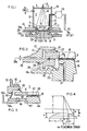
- a X-ray lithography system 10 incorporating the invention is seen in Fig. 1.
- An exposure chamber 11 is formed by cylindrical walls 1 2 and an inwardly extending bottom flange 9 forming an exit 6, X-rays, illustrated by rays 14 eminating from an X-ray source or target 13 in a source vacuum chamber, through a beryllium window 7 in an exposure chamber top closure 5.
- the particular design of the chamber 11 or the vacuum chamber containing source 13 is not critical to this invention other than the relationship of the exit and flange or other equivalent structure with the mask and mask holder, respectively.
- a supply of helium or other gas which does not attenuate the transmission of X-rays enters chamber 11 through upper inlet 4 remote from the mask.
- the purity of the helium must be kept high to reduce the X-ray exposure time to a minimum and wafer printing production to a maximum.
- Al characteristic X-rays at 1.5KeV are attenuated 5% and 42% given a helium purity of 99.90% and 99.00% respectively.
- the assumed contaminant would be air in each case.
- the attenuation for the same two levels of helium purity would be about 1% and 7% respectively.
- the amount of helium gas used during wafer processing must be minimized from an economic standpoint.
- a mask holder 15 typically of the type shown in the related application of Anwar Husain (now US-A-4,544,311) referenced above, abuts at a thick peripheral portion 16 with the underside of flange 9.
- a silicone rubber or other resilient soft seal (not shown) is placed between these surfaces to prevent ingress or egress of gases.
- a wafer chuck 19 mounts on its top surface a semiconductor substrate or wafer 20 on which various electronic circuit patterns may be irradiated and fixed on a coating of X-ray resist material, as is known in the art.
- the wafer and mask membrane are accurately aligned with respect to each other, as set forth for example in the related Novak application, and gapped so as to be in parallel planes with a prescribed vertical gap therebetween typically of about 40 microns.
- a helium vent tube 21 of reversed U-shaped configuration is provided within chamber 11 to prevent a pressure differential across mask membrane 18.
- the helium vents to the exterior of the chamber through the tube 21 at near the minimum velocity required to prevent back diffusion of oxygen or nitrogen molecules into the vent tube through end orifice 23.
- the tube and any orifices along it are the minimum diameter necessary to prevent any back flow or diffusion, but are not so small as to cause significant deflection of the membrane 18.
- Significant deflection would otherwise change or distort the gap distance between or across the mask membrane and the wafer and would result in mask-to-wafer registration errors.
- the maximum deflection allowed is in the range of 1 to 5 microns, depending on the criticality of the concerned wafer processing step.
- ⁇ /r 2 o P/(4St).
- S 10 8 dynes/cm 2
- t 4 ⁇ m
- P 10 dyne/cm 2
- A then equals 8 microns.
- Letting r 1 3.0 cm, the maximum error in alignment (Ae) is then 0.08 microns, which is an acceptable value for wafer diameters of 10 cm.
- the helium gas is introduced at the top of the chamber through inlet 4 and since the gas has a lower density than. the air or air contaminated helium, the contaminated gas tends to settle downward toward the bottom of the chamber. Therefore, the interior end 22 of the vent tube 21 is as close as possible to the mask membrane surface 18, or the lowest point in the chamber (if lower than the mask). Thus the most contaminated gas is vented out of the chamber.
- a silicone rubber seal 27 at the top of the mask 17 is used to prevent helium contamination from the gases exterior to the mask. Since there is a density difference between helium and air, and since there must be zero pressure differential across the mask membrane, a slight positive pressure exists at all levels above the mask within the chamber.
- the exterior end or orifice 23 of the vent tube must be near or approximate the level of the mask surface.
- the vertical height of the end of the tube can be "tuned” to vary the pressure on the top side of the mask and hence zero the differential across the mask by providing a screw threaded extension or sliding adjustable end on the tube end 23.
- This tuning phenomenon follows hydraulic principles common when dealing with liquids.
- the densities of N 2 (air) and helium at 0°C and 760 torr are 1.25 grams/liter and 0.18 grams/liter respectively. The difference is 1 . 07 X 10- 3 grams/cm 3 .
- a 1 cm height change of the exterior end of the helium vent tube corresponds to a pressure change of 1.07 X 10 -3 grams/cm 2 or about 1 dyne/cm 2 .
- the pressure differential at the mask membrane here assumed to be 10 dynes/cm 2
- a small chamber 24 containing an oxygen detector This detector which can be a Model 320 AY manufactured by Teledyne Analytical Instruments is used to monitor the purity of the helium so that helium usage can be minimized.
- the height of tube 21 which can go up in direction or down is not critical. If the helium tube has an inside diameter of 6.0mm, then the calculated flow rate, assuming a pressure differential of 10 dynes/cm, is about 0.4 liters/minute. This corresponds to a helium velocity in the tube of 20 cm/sec. which is sufficient to prevent back-streaming (or back diffusion) of ambient air through orifice 23 back to chamber 11.
- the normal operating sequence is as follows: after the mask 17 has been loaded in holder 15 and is in place against the seal 27, the helium is turned on at a relatively high flow rate typically about 8 liters/minute. When the purity reaches a preset value, a low helium flow of the order of 0.4 liters/minute is set to maintain this purity. If minor leakage is present or if greater pressure differential is allowed, the flow rate may be significantly higher, for example up to 4.0 liters/min. depending on the specific embodiment. An analog signal from the oxygen detector can be outputted and used by a service technician to optimize the low flow rate if required.
- the helium is vented to the atmosphere, but in such a manner as to minimize the helium use and contamination level.
- the helium pressure just above the mask membrane is adjusted relative to the pressure existing in the mask-to-wafer zone 3 to minimize the pressure differential between the top and bottom surfaces of the mask membrane.
- Control of the pressure on the underside of membrane 18 in and around mask-to-wafer zone 3 is effected by various means.
- the gas used in this zone is termed a wafer fabrication process gas since it effects the printing quality on the semiconductor wafer.
- the process gas may be a nitrogen gas containing 0.3% oxygen, as taught by the U. S. Patent 4,185,202.
- Process gas enters via the gas inlet 31 in chuck 19 to provide the proper atmosphere around the periphery of the wafer and in the mask-to-wafer gap in zone 3.
- a circular gas flange 25 is interposed between a peripheral extension 19a of chuck 19 and the underside of mask holder 15 leaving gaps 26a and 26b, respectively, therebetween.
- a silicone rubber seal 27a is used to prevent contaminating air passing through the gap between chuck 19a and gas flange 25 to zone 3. No seal can be placed between the gas flange and mask holder frame in gap 26b. Such a seal would endanger the pressure balance across the mask membrane. Instead, a long thin path indicated by 26b in the Fig. 2 is provided to allow the purging gas to escape to the outside, without a detectable pressure buildup affecting the mask membrane position i.e. preventing deflection. Gap 26b is of a value of about 10 to about 1000 microns.
- the gas must flow at a rate which is faster than the back diffusion rate for air, and in this case, the flow must be sufficiently uniform so that no atmospheric contamination is drawn into the wafer zone during wafer exposure to the X-rays.
- a higher flow rate of about 5 liters/ minute is used initially, as the wafer is being brought toward the mask. At this time, the gap is large between the mask and wafer, and the air, which is initially present, is swept away. The flow rate is reduced after the nominal mask-to-wafer gap is established to about 1.0 ⁇ 0.5 liters/minute.
- Upstanding interdigitated embossments forming X-ray seals 28-30 extend in a circular pattern on facing surfaces of the chuck peripheral edge 19a and the gas flange providing a tortious path which prevents stray X-rays from around the periphery of the mask or mask membrane exiting from the apparatus.
- the bottom of seal 28 is at a level below the top of seals 29 and 30 and seal 28 is positioned midway of the chuck seals 29 and 30.
- Circular seal 27a is inboard of the X-ray seals.
- Fig. 2 shows a magnified cross-sectional view of the left side of Fig. 1 showing the placement of seals 27 and 27a and the relative size of the gaps between the various surfaces.
- a mask-to-wafer gap of 40 microns the preferred gap spacing between the underside of mask holder 17 and the top of gas flange 25 is of the order of from 250 to 350 microns and gap 26b is of the order of 500 microns.
- the membrane 18 is affixed to a frame 17a of mask 17 for example as shown in the related Husain application. Frame 17a is sealed to holder 15 by the circular flexible seal 27.
- the gap 26a around the periphery of the mask and wafer tends to restrict the flow of process gas into the ambient and therefore a small pressure differential may exist between the chamber area 3 and the ambient. This in turn will cause the mask membrane 18 to deflect toward due to the pressure differential that results across the membrane. Control of the process gas flows for a given gap 26a can therefore be used to compensate for the downward mask deflection which may result from the helium flow into the chamber 11 as described previously.
- a tool or the system's optical alignment system can be used to measure the mask deflection from nominal. With the chamber 11 filled with helium and the volume 3 filled with process gas, using near normal, but uncalibrated flow rates, the flows are shut off to zero and the mask membrane 18 allowed to come to equilibrium. The sensor means used to measure the mask deflection is calibrated to zero. Next, the helium flow through inlet 4 is increased to that necessary to maintain the correct helium purity in the chamber 11. The process gas is then turned on and increased until any mask deflection is nulled. The process gas purity in volume 3 should be correct. The helium outlet 23 is.fixed in the present embodiment at the mask membrane level.
- the helium vent outlet can be lowered to compensate for the expected deflection.
- the mask downward deflection caused by reducing the process gas flow can be compensated for by raising the end of the helium vent outlet.
- this solution may increase the demand on the integrity of the seals 27 and 16 since the net positive pressure across the seals will be reduced.
- Fig. 3 illustrates an alternative embodiment (not designed for a step and repeat system) of the invention wherein the process gas pressure and purity is controlled by a circular silicone rubber seal 45 around the wafer and mask to prevent the influx of atmospheric gases into the mask-to-wafer zone 48 and a vent tube 46 is employed, similar to the helium vent tube described previously.
- This vent tube must have an exterior termination or end orifice 46a at the level of the mask. This is needed also, if there is any appreciable density difference between the process gas and ambient air, at the same pressure. This density difference will tend to promote vertical movement and may cause the gas containment and control problem to be more difficult depending on the mechanical design.
- a mask holder 40 abuts the underside of flange 9 of cylinder 12.
- the mask 41 which may be attached to the holder as seen in the Husain related application is sealed thereto by a silicone rubber ring seal 43.
- the mask-to-wafer zone 48 is sealed by a circular silicone rubber ring seal 45 extending from the bottom of mask holder 40 to a peripheral flange 44a on chuck 44.
- Process gas enters through one or more inlets 47 around the periphery of chuck 44 adjacent to the wafer-holding central portion.
- Zone 48 extends in the gap 49 between mask membrane 42 and wafer 20 and around the periphery of wafer 20.
- Venting of the process gas is provided through vent tube 46 which extends upwardly to ambient air at orifice end 46a at a level equal or approximate to about the level of the mask membrane.
- the pressure on the top and bottom of the mask membrane are equal or of a differential not sufficient to cause significant membrane deflection or vibration.
Landscapes
- Health & Medical Sciences (AREA)
- Toxicology (AREA)
- Physics & Mathematics (AREA)
- General Physics & Mathematics (AREA)
- Life Sciences & Earth Sciences (AREA)
- Atmospheric Sciences (AREA)
- Engineering & Computer Science (AREA)
- Environmental & Geological Engineering (AREA)
- Epidemiology (AREA)
- Public Health (AREA)
- Exposure And Positioning Against Photoresist Photosensitive Materials (AREA)
- Exposure Of Semiconductors, Excluding Electron Or Ion Beam Exposure (AREA)
Applications Claiming Priority (2)
| Application Number | Priority Date | Filing Date | Title |
|---|---|---|---|
| US673964 | 1984-11-21 | ||
| US06/673,964 US4648106A (en) | 1984-11-21 | 1984-11-21 | Gas control for X-ray lithographic system |
Publications (2)
| Publication Number | Publication Date |
|---|---|
| EP0182443A2 true EP0182443A2 (fr) | 1986-05-28 |
| EP0182443A3 EP0182443A3 (fr) | 1987-10-28 |
Family
ID=24704803
Family Applications (1)
| Application Number | Title | Priority Date | Filing Date |
|---|---|---|---|
| EP85201909A Withdrawn EP0182443A3 (fr) | 1984-11-21 | 1985-11-19 | Système lithographique à rayons X, en particulier sa régulation gazeuse ainsi que procédé de fabrication d'un substrat semi-conducteur |
Country Status (3)
| Country | Link |
|---|---|
| US (1) | US4648106A (fr) |
| EP (1) | EP0182443A3 (fr) |
| JP (1) | JPS61180440A (fr) |
Cited By (1)
| Publication number | Priority date | Publication date | Assignee | Title |
|---|---|---|---|---|
| US6653639B1 (en) | 2000-10-17 | 2003-11-25 | Nikon Corporation | Chuck for mounting reticle to a reticle stage |
Families Citing this family (13)
| Publication number | Priority date | Publication date | Assignee | Title |
|---|---|---|---|---|
| JPS6197918A (ja) * | 1984-10-19 | 1986-05-16 | Hitachi Ltd | X線露光装置 |
| JPH0687408B2 (ja) * | 1986-03-07 | 1994-11-02 | 株式会社日立製作所 | プラズマx線発生装置 |
| JPH01139237U (fr) * | 1988-03-15 | 1989-09-22 | ||
| JP2676526B2 (ja) * | 1988-06-09 | 1997-11-17 | 富士通株式会社 | X線露光装置 |
| JP2766935B2 (ja) * | 1989-10-20 | 1998-06-18 | キヤノン株式会社 | X線露光装置 |
| JP3377165B2 (ja) * | 1997-05-19 | 2003-02-17 | キヤノン株式会社 | 半導体露光装置 |
| US6459472B1 (en) | 1998-05-15 | 2002-10-01 | Asml Netherlands B.V. | Lithographic device |
| US6198792B1 (en) * | 1998-11-06 | 2001-03-06 | Euv Llc | Wafer chamber having a gas curtain for extreme-UV lithography |
| JP4849598B2 (ja) * | 2006-01-13 | 2012-01-11 | Nskテクノロジー株式会社 | 露光装置 |
| JP4735272B2 (ja) * | 2006-01-13 | 2011-07-27 | 日本精工株式会社 | 露光装置 |
| NL2008345A (en) * | 2011-03-28 | 2012-10-01 | Asml Holding Nv | Lithographic apparatus and device manufacturing method. |
| WO2015112467A1 (fr) * | 2014-01-21 | 2015-07-30 | Applied Materials, Inc. | Chambre de traitement de dépôt de couche atomique permettant un remplacement d'outil à basse pression |
| NL2017806B1 (nl) * | 2016-11-16 | 2018-05-25 | Suess Microtec Photomask Equipment Gmbh & Co Kg | Holder for receiving and for protecting one side of a photomask or of a photomask with pellicle from a cleaning medium, method for cleaning a photomask or a photomask with pellicle and apparatus for opening and closing a holder |
Family Cites Families (5)
| Publication number | Priority date | Publication date | Assignee | Title |
|---|---|---|---|---|
| US4085329A (en) * | 1976-05-03 | 1978-04-18 | Hughes Aircraft Company | Hard X-ray and fluorescent X-ray detection of alignment marks for precision mask alignment |
| US4185202A (en) * | 1977-12-05 | 1980-01-22 | Bell Telephone Laboratories, Incorporated | X-ray lithography |
| US4453262A (en) * | 1978-01-16 | 1984-06-05 | The Perkin-Elmer Corporation | X-Ray lithography apparatus and method of use |
| JPS59101833A (ja) * | 1982-12-03 | 1984-06-12 | Hitachi Ltd | X線露光装置 |
| JPS6197918A (ja) * | 1984-10-19 | 1986-05-16 | Hitachi Ltd | X線露光装置 |
-
1984
- 1984-11-21 US US06/673,964 patent/US4648106A/en not_active Expired - Fee Related
-
1985
- 1985-11-19 EP EP85201909A patent/EP0182443A3/fr not_active Withdrawn
- 1985-11-21 JP JP60259940A patent/JPS61180440A/ja active Pending
Cited By (1)
| Publication number | Priority date | Publication date | Assignee | Title |
|---|---|---|---|---|
| US6653639B1 (en) | 2000-10-17 | 2003-11-25 | Nikon Corporation | Chuck for mounting reticle to a reticle stage |
Also Published As
| Publication number | Publication date |
|---|---|
| EP0182443A3 (fr) | 1987-10-28 |
| JPS61180440A (ja) | 1986-08-13 |
| US4648106A (en) | 1987-03-03 |
Similar Documents
| Publication | Publication Date | Title |
|---|---|---|
| US4648106A (en) | Gas control for X-ray lithographic system | |
| EP1207425B1 (fr) | Appareil d' exposition | |
| KR100518064B1 (ko) | 불활성가스퍼지방법 및 장치, 노광방법, 레티클보관고,레티클검사장치, 레티클반송박스, 및 디바이스제조방법 | |
| EP0532968B1 (fr) | Appareil à rayons-X pour lithographie par projection | |
| US6809799B2 (en) | Processing system and device manufacturing method using the same | |
| US6317479B1 (en) | X-ray mask, and exposure method and apparatus using the same | |
| US4851097A (en) | Apparatus for repairing a pattern film | |
| US20060209278A1 (en) | Exposure apparatus and device manufacturing method | |
| JPH0638388B2 (ja) | マイクロリソグラフイ装置 | |
| EP0424181B1 (fr) | Appareil pour l'exposition aux rayons X | |
| US7576833B2 (en) | Gas curtain type immersion lithography tool using porous material for fluid removal | |
| US20050068512A1 (en) | Optical unit, exposure apparatus, and device manufacturing method | |
| EP0110414A2 (fr) | Appareil de lithographie par rayons X | |
| US7463331B2 (en) | Exposure apparatus and method for manufacturing device | |
| EP0540302B1 (fr) | Appareil d'exposition aux rayons-x et méthode de fabrication de dispositifs semi-conducteurs | |
| US20040169832A1 (en) | Vacuum chamber having instrument-mounting bulkhead exhibiting reduced deformation in response to pressure differential, and energy-beam systems comprising same | |
| JP2006060037A (ja) | 露光装置 | |
| US7119952B2 (en) | Optical instrument, exposure apparatus, and device manufacturing method | |
| KR20060120649A (ko) | 오염으로부터 레티클을 보호하기 위해 사용된 펠리클에대한 중력의 영향을 보상하기 위한 방법 및 장치 | |
| KR20050044800A (ko) | 투영 조사 시스템을 시일하는 장치 | |
| JPS6167917A (ja) | X線取り出し筒 | |
| JPH0438814A (ja) | X線露光装置 | |
| EP0363163B1 (fr) | Appareil pour l'exposition aux rayons X | |
| JP2003332214A (ja) | 減圧装置、基板の制御方法、露光装置、半導体デバイスの製造方法 | |
| KR20020077509A (ko) | 포토 마스크 유닛, 포토 마스크 장치, 투영 노광 장치 및반도체 장치 |
Legal Events
| Date | Code | Title | Description |
|---|---|---|---|
| PUAI | Public reference made under article 153(3) epc to a published international application that has entered the european phase |
Free format text: ORIGINAL CODE: 0009012 |
|
| AK | Designated contracting states |
Kind code of ref document: A2 Designated state(s): CH DE FR GB IT LI |
|
| PUAL | Search report despatched |
Free format text: ORIGINAL CODE: 0009013 |
|
| AK | Designated contracting states |
Kind code of ref document: A3 Designated state(s): CH DE FR GB IT LI |
|
| STAA | Information on the status of an ep patent application or granted ep patent |
Free format text: STATUS: THE APPLICATION IS DEEMED TO BE WITHDRAWN |
|
| 18D | Application deemed to be withdrawn |
Effective date: 19871201 |
|
| RIN1 | Information on inventor provided before grant (corrected) |
Inventor name: NOVAK, THOMAS W. |