EP0182489B1 - Joint pour élément rotatif contenant un orifice de pulvérisation - Google Patents
Joint pour élément rotatif contenant un orifice de pulvérisation Download PDFInfo
- Publication number
- EP0182489B1 EP0182489B1 EP85307280A EP85307280A EP0182489B1 EP 0182489 B1 EP0182489 B1 EP 0182489B1 EP 85307280 A EP85307280 A EP 85307280A EP 85307280 A EP85307280 A EP 85307280A EP 0182489 B1 EP0182489 B1 EP 0182489B1
- Authority
- EP
- European Patent Office
- Prior art keywords
- seal
- spray tip
- piston
- turret member
- spray
- Prior art date
- Legal status (The legal status is an assumption and is not a legal conclusion. Google has not performed a legal analysis and makes no representation as to the accuracy of the status listed.)
- Expired
Links
- 239000007921 spray Substances 0.000 title claims description 74
- 239000004033 plastic Substances 0.000 claims description 14
- 229920003023 plastic Polymers 0.000 claims description 14
- 230000002829 reductive effect Effects 0.000 claims description 8
- 238000011144 upstream manufacturing Methods 0.000 claims description 8
- 230000006835 compression Effects 0.000 claims description 7
- 238000007906 compression Methods 0.000 claims description 7
- 238000007789 sealing Methods 0.000 claims description 7
- DHKHKXVYLBGOIT-UHFFFAOYSA-N acetaldehyde Diethyl Acetal Natural products CCOC(C)OCC DHKHKXVYLBGOIT-UHFFFAOYSA-N 0.000 claims description 6
- 229920001577 copolymer Polymers 0.000 claims description 6
- 230000002787 reinforcement Effects 0.000 claims description 5
- 239000002990 reinforced plastic Substances 0.000 claims description 2
- 239000000463 material Substances 0.000 claims 5
- 239000011152 fibreglass Substances 0.000 claims 1
- 229920006324 polyoxymethylene Polymers 0.000 claims 1
- 238000005507 spraying Methods 0.000 description 6
- 238000010276 construction Methods 0.000 description 5
- 239000007788 liquid Substances 0.000 description 5
- 230000002441 reversible effect Effects 0.000 description 5
- OKTJSMMVPCPJKN-UHFFFAOYSA-N Carbon Chemical compound [C] OKTJSMMVPCPJKN-UHFFFAOYSA-N 0.000 description 3
- 238000004140 cleaning Methods 0.000 description 3
- 239000003365 glass fiber Substances 0.000 description 3
- 239000002184 metal Substances 0.000 description 3
- 229920000642 polymer Polymers 0.000 description 3
- 230000000717 retained effect Effects 0.000 description 3
- VYPSYNLAJGMNEJ-UHFFFAOYSA-N Silicium dioxide Chemical compound O=[Si]=O VYPSYNLAJGMNEJ-UHFFFAOYSA-N 0.000 description 2
- 229910052799 carbon Inorganic materials 0.000 description 2
- 239000000945 filler Substances 0.000 description 2
- 229910002804 graphite Inorganic materials 0.000 description 2
- 239000010439 graphite Substances 0.000 description 2
- 230000000670 limiting effect Effects 0.000 description 2
- 239000007787 solid Substances 0.000 description 2
- BGJSXRVXTHVRSN-UHFFFAOYSA-N 1,3,5-trioxane Chemical compound C1OCOCO1 BGJSXRVXTHVRSN-UHFFFAOYSA-N 0.000 description 1
- 239000004677 Nylon Substances 0.000 description 1
- 239000004734 Polyphenylene sulfide Substances 0.000 description 1
- 125000002777 acetyl group Chemical class [H]C([H])([H])C(*)=O 0.000 description 1
- PNEYBMLMFCGWSK-UHFFFAOYSA-N aluminium oxide Inorganic materials [O-2].[O-2].[O-2].[Al+3].[Al+3] PNEYBMLMFCGWSK-UHFFFAOYSA-N 0.000 description 1
- 238000007334 copolymerization reaction Methods 0.000 description 1
- 230000001419 dependent effect Effects 0.000 description 1
- 238000000605 extraction Methods 0.000 description 1
- 239000012530 fluid Substances 0.000 description 1
- 229920001519 homopolymer Polymers 0.000 description 1
- 229920001778 nylon Polymers 0.000 description 1
- 238000012856 packing Methods 0.000 description 1
- 230000036961 partial effect Effects 0.000 description 1
- 229920002492 poly(sulfone) Polymers 0.000 description 1
- 229920000515 polycarbonate Polymers 0.000 description 1
- 239000004417 polycarbonate Substances 0.000 description 1
- 229920000069 polyphenylene sulfide Polymers 0.000 description 1
- 239000000843 powder Substances 0.000 description 1
- 230000002035 prolonged effect Effects 0.000 description 1
- 239000000377 silicon dioxide Substances 0.000 description 1
- 230000002459 sustained effect Effects 0.000 description 1
- 229920001169 thermoplastic Polymers 0.000 description 1
- 229920001187 thermosetting polymer Polymers 0.000 description 1
- 239000004416 thermosoftening plastic Substances 0.000 description 1
Images
Classifications
-
- B—PERFORMING OPERATIONS; TRANSPORTING
- B05—SPRAYING OR ATOMISING IN GENERAL; APPLYING FLUENT MATERIALS TO SURFACES, IN GENERAL
- B05B—SPRAYING APPARATUS; ATOMISING APPARATUS; NOZZLES
- B05B9/00—Spraying apparatus for discharge of liquids or other fluent material, without essentially mixing with gas or vapour
- B05B9/01—Spray pistols, discharge devices
-
- B—PERFORMING OPERATIONS; TRANSPORTING
- B05—SPRAYING OR ATOMISING IN GENERAL; APPLYING FLUENT MATERIALS TO SURFACES, IN GENERAL
- B05B—SPRAYING APPARATUS; ATOMISING APPARATUS; NOZZLES
- B05B15/00—Details of spraying plant or spraying apparatus not otherwise provided for; Accessories
- B05B15/50—Arrangements for cleaning; Arrangements for preventing deposits, drying-out or blockage; Arrangements for detecting improper discharge caused by the presence of foreign matter
- B05B15/52—Arrangements for cleaning; Arrangements for preventing deposits, drying-out or blockage; Arrangements for detecting improper discharge caused by the presence of foreign matter for removal of clogging particles
- B05B15/531—Arrangements for cleaning; Arrangements for preventing deposits, drying-out or blockage; Arrangements for detecting improper discharge caused by the presence of foreign matter for removal of clogging particles using backflow
- B05B15/534—Arrangements for cleaning; Arrangements for preventing deposits, drying-out or blockage; Arrangements for detecting improper discharge caused by the presence of foreign matter for removal of clogging particles using backflow by reversing the nozzle relative to the supply conduit
Definitions
- This invention relates to a spray tip for airless spraying according to the preamble of claim 1, and, in particular, to such a spray tip provided with a reversible and interchangeable turret member.
- a spray tip assembly in which the spray tip orifice is mounted in a cylindrical turret member which can be rotated in the housing to reverse the orifice member for cleaning.
- This construction employs a solid, resilient plastic seal which has a concave, cylindrical sealing surface.
- US-A-3,202,360 also discloses an airless spray tip having a rotatable turret member, which is sealed with a packing sleeve and nut.
- US-A-4,165,836 discloses that plastic seals experience excessive wear and suggests that an entirely metal seal be used to provide metal-to- metal contact with the turret member.
- an entirely metal seal be used to provide metal-to- metal contact with the turret member.
- a metal seal is not effective with low viscosity liquids, which leak from the assembly under the high pressures used in airless spraying.
- the invention as claimed provides a spray tip useful for high pressure, airless spraying which utilizes a turret member which contains an orifice tip.
- the turret member is rotationally mounted in the spray tip housing so that it is reversible and is interchangeable with other holders supporting orifice tips of varied diameters and capacities.
- the spray tip member uses a seal subassembly which is received in the longitudinal through passageway of the housing, and this subassembly includes a seal formed entirely of a reinforced plastic.
- a very hard plastic such as an acetal copolymer is used and, preferably, this plastic is reinforced with glass fibers.
- the seal is mounted on one end of a piston that is slidably received in the through bore of the adapter, and is resiliently biased to compress the seal against the turret member.
- the piston On its opposite end, the piston is engaged by a compression spring that is captured between the upstream end of the piston and the end face of the barrel of the spray gun on which the spray tip is mounted, to provide the resilient bias for sealing the turret member.
- the spray tip of this invention provides very superior performance over all other spray tips.
- the seal is indexed and restrained against rotation and dislodgement when the turret member is removed, thereby facilitating replacement of the turret member.
- the seal is very effective, even with very low viscosity liquids and effectively seals the turret member against all leakage of the spray liquid.
- the spring biasing the seal sub- assembly provides a number of advantages. When the tip is placed on a spray gun, the retainer nut can be hand tightened to compress the spring sufficiently to restrain the turret member from falling out of the tip, thus freeing one's hand to apply a wrench for final tightening of the retainer nut and to rotate the tip to the desired alignment on the spray gun.
- the spring When the retainer nut is tightened sufficiently to prevent leaking under pressure, the spring still provides sufficient resilient bias on the seal to maintain a dynamic seal which freely permits one to rotate the turret member between its cleaning and spraying positions with finger pressure and without releasing the tension on the retainer nut.
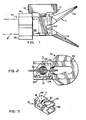
- FIGURES 1 and 2 the invention is shown with a spray guard 10 mounted on a housing body 12 which supports a turret member 14.
- the turret member has a dependent handle 16 on shaft 18 which extends to a cylindrical turret member described in detail hereinafter.
- the spray guard body 26 has an aperture 28 which receives the turret member 14.
- the turret member 14 has a radial prong 20 and aperture 28 in spray guard 10 has a notch 32 which permits extraction of the turret member when the latter is rotated to align prong 20 beneath notch 32.
- body 12 is also shown in FIGURE 3 with the turret member 14 and spray guard 10 removed.
- body 12 of the spray tip housing has a longitudinal chamber 46 of non- circular, preferably rectangular, cross-section.
- the end wall 48 is bored to provide the central aperture 15.
- the housing body 12 also has a cylindrical bore 30 orthogonal to and intersecting the longitudinal chamber 46 and this cylindrical bore 30 receives the cylindrical turret member 14.
- the top wall 17 of the body 12 has a raised annular shoulder 19 and abutment stops 22 and 24 at its opposite edges. As shown in FIGURE 2, these abutment stops serve as limiting stops for the rotation of the turret member, engaging prong 20 and permitting rotation of the turret member through 180 degrees of rotation. These rotation limiting stops are engaged when the turret member is in either its cleaning or spraying positions.
- the spray guard 10 has a square. cross-sectional body 26 with a central cavity 38 that fits over the rectangular body 12 of the spray tip.
- the spray guard 10 has a pair of outwardly diverging wings 40 and 42 which are generally trapezoidal. At the apex or intersection of wings 40 and 42, the spray guard has a slot 44 to provide clearance for the spray discharged from the spray tip.
- Each of the outwardly diverging wings 40 and 42 has a longitudinal, central, through slot such as 41. As illustrated for the preferred embodiment, the slots are narrow and extend substantially the entire length of wings 40 and 42.
- the spray tip assembly is retained on the externally threaded barrel 21 of a spray gun by the retainer cap nut 34. Tightening of this nut on the threaded barrel of the spray gun axially compresses the internal seals of assembly in the manner described in greater detail hereinafter.
- lugs 36 can be provided to permit hand tightening of cap nut 34.
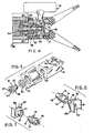
- the spray tip assembly is shown in greater detail, removed from barrel 21 of the spray gun.
- the turret member 14 is received in bore 30 of the housing body 12 and extends across the longitudinal chamber 46.
- the turret member carries a spray tip orifice member 56 in a transverse bore 52.
- the housing body 12 is assembled to a housing adapter 58 to form a housing subassembly, which is shown in exploded view by FIGURE 5.
- the adapter 58 has a through bore 63 and a threaded end 57 and an annular shoulder 61.
- Adapter 58 has an end flange 60 that is received within the retainer nut 34, and a low frictional characteristic, bearing washer 62 is captured between the annular rim 64 (see FIGURE 4) of retainer nut 34 and flange 60 of adapter 58 and provides very low frictional resistance between the retainer nut 34 and the assembly of body 12 and adapter 58, when the retainer nut 34 is tightened.
- the housing subassembly is permanently secured by threading adapter 58 into internally threaded bore 50 in body 12.
- wrench flats 65 are formed on the internal end wall of bore 63 of adapter 58.
- the bore 50 also has a square shoulder, i.e., is unchamfered, to provide an abutment stop which precisely controls the axial positioning of adapter 58 provides the inlet port to the housing body 12, and this passage 63 receives the seal subassembly, which is also illustrated in FIGURE 4, and in an exploded view by FIGURE 6.
- the seal subassembly (see FIGURE 6) comprises a piston 76 with a through bore 77 which aligns with a central through bore 87 in seal 88.
- the seal 88 has a square face 89, to fit the square cross-sectional chamber 46 of body 12.
- the rear face of seal 88 has a boss 90 and a reduced diameter neck 92 which is received in a counterbore 74 of piston 76.
- Piston 76 has an annular groove 75 which receives a sealing washer, e.g., an O-ring 80 (see FIGURE 4) to seal the piston in the central passage 63 of adapter 58.
- the upstream end of piston 76 has a reduced diameter neck 78 and a compression spring 66 is received over this neck.
- the assembly of the spray tip on a spray gun and tightening of the retainer cap nut 34 on the threaded barrel 21 (see FIGURE 1) of the spray gun applies an axial compression to the seal assembly.
- the compression spring 66 bears against the end of the spray gun barrel and applies a resilient force to the piston 76, ensuring that a constant loading is applied to the seal 88, regardless of the tension applied to the retainer nut 34.
- a seal washer 69 is retained between the end of the spray gun barrel and the inside face of flange 60 of adapter 58.
- the turret member 14 has a transverse bore 52 which is counterbored at 54 to receive spray tip orifice member 56.
- the orifice member 56 is firmly seated against the annular shoulder between bore 54 and counterbore 56.
- Bore 52 should be of sufficient length that the orifice tip 56 does not project beyond the cylindrical surface of turret member 14.
- the orifice member 56 is retained in the assembly by sleeve 55 which is pressed into the counterbore 54 and a sealing washer 57 is compressed against the orifice member 56 to seal this member in the counterbore 56.
- the seal 88 is substantially the same as previously described with a square face 89 to fit in the chamber 46 of housing body 12.
- the rear face of seal 88 has a boss 90 which has an enlarged counterbore 93.
- the piston 76 has a reduced diameter neck 79 on its downstream end and this neck fits into the counterbore 93 of the seal 88.
- the remainder of the seal subassembly is the same as previously described with reference to FIGURE 6, with annular groove 75 which receives and 0-ring 80 to seal the piston in the central passage 57 of adapter 58 and a reduced diameter neck 78 on its upstream end to receive compression spring 66, previously described.
- the seal is formed entirely of plastic, which is filled with from 5 to 50, preferably from 15 to about 30, weight percent of a reinforcement filler.
- plastics can be used for this purpose, including acetal homopolymer and copolymer, polysulfones, polyphenylene sulfide, polycarbonate, thermosetting and thermoplastic polyimdes, Nylon, poly(amide-imide), etc.
- Acetal copolymer is preferred for its hardness and wear resistance.
- acetal copolymers have Rockwell hardness values from M78 to M80 by the ASTM D785 test.
- the acetal copolymer is prepared by the copolymerization of trioxane with slight amounts of a comonomer which provides carbon to carbon bonding in the polymer chain, thereby imparting a high degree of thermal stability to the polymer.
- the polymer has a very high creep resistance and a tensile strength in excess of 1054 kilograms per square centimeter.
- the fillers which can be used for reinforcement of the plastic seal body include graphite, silica, alumina powders, and fibrous reinforcements such as graphite and glass fibers.
- fibrous reinforcements such as graphite and glass fibers.
- glass fibers having lengths from about 0.23 to about 0.63 centimeters are used.
- the spray tip of this invention is provided with a plurality of interchangeable turret members with varied sizes of orifice tips to permit the user to switch turret members whenever it is desired to change the volume or spread of the fan spray.
- the orifice tips can be provided in sizes from about 0.023 to about 0.19 centimeter in any varied increments, preferably in increments from about 0.003 to 0.008 centimeter. These orifice tips will provide a fan spray with a width from 5 to about 55 centimeters in approximately 5 centimeter increments.
- the cylindrically concave face 89 of the seal remains in axial alignment with the cylindrical bore 309 when the turret member is removed or replaced. Also, since the seal support 76 is restrained by its frictional fit with the piston 76, it can not fall out of position when the turret member is removed. Instead, it resists dislodgement and remains in place to ensure that the turret member, or a replacement turret member, can be quickly inserted without need to reposition the seal support.
- the invention provides a number of definite advantages over prior spray tips.
- the plastic seal of the invention tightly seals and minimizes leakage even with low viscosity liquids.
- the rigid seal support firmly supports the seal, and the compression spring ensures that the seal does not seize the turret member and prevent its rotation by hand, even when the spray tip has been mounted on the spray gun for a prolonged period.
- the turret member can be quickly reversed to its clean-out position, any obstructions can be sprayed out of the orifice, and the turret member can be returned to its spraying position, all without loosening the retainer nut.
- the turret member is easily removable from the spray tip simply by loosening retainer cap nut 30 and rotating the turret member to align its prong with the notch of the spray guard.
- the seal and seal support remain in place to permit rapid replacement of the turret member.
- the retainer cap nut can be tightened and loosened by hand and the spray tip can be rotated on the spray gun without loosening the cap nut.
Landscapes
- Details Or Accessories Of Spraying Plant Or Apparatus (AREA)
Claims (12)
Applications Claiming Priority (2)
| Application Number | Priority Date | Filing Date | Title |
|---|---|---|---|
| US66261584A | 1984-10-19 | 1984-10-19 | |
| US662615 | 1984-10-19 |
Publications (2)
| Publication Number | Publication Date |
|---|---|
| EP0182489A1 EP0182489A1 (fr) | 1986-05-28 |
| EP0182489B1 true EP0182489B1 (fr) | 1988-12-21 |
Family
ID=24658437
Family Applications (1)
| Application Number | Title | Priority Date | Filing Date |
|---|---|---|---|
| EP85307280A Expired EP0182489B1 (fr) | 1984-10-19 | 1985-10-11 | Joint pour élément rotatif contenant un orifice de pulvérisation |
Country Status (2)
| Country | Link |
|---|---|
| EP (1) | EP0182489B1 (fr) |
| DE (1) | DE3566869D1 (fr) |
Families Citing this family (7)
| Publication number | Priority date | Publication date | Assignee | Title |
|---|---|---|---|---|
| US4685621A (en) * | 1986-03-24 | 1987-08-11 | Graco, Inc. | Accumulation resistant tip guard |
| DE8803389U1 (de) * | 1988-03-12 | 1988-05-19 | J. Wagner GmbH, 7778 Markdorf | Düsen-Wechselhalter für Hochdruck-Farbspritzpistolen |
| US5340029A (en) * | 1993-04-05 | 1994-08-23 | Spraying Systems Co. | Rotary spray tip assembly with improved rotor sealing means |
| US5749528A (en) * | 1995-12-27 | 1998-05-12 | Titan Tool, Inc. | Reversible spray tip |
| DE29622482U1 (de) * | 1996-12-27 | 1997-02-13 | Goldberg, Hans, 88709 Hagnau | Vorrichtung zum Reinigen verstopfter Düsen bei der kombinierten pneumatisch-hydraulischen Zerstäubung |
| BR112017017216B1 (pt) | 2015-02-13 | 2022-09-27 | Chemetall Gmbh | Método para vedação, revestimento ou/e nivelamento aerodinâmico de pelo menos um elemento de conexão, aparelho automático, e, uso do método inventivo ou/e do aparelho inventivo |
| WO2021222200A1 (fr) * | 2020-04-29 | 2021-11-04 | Graco Minnesota Inc. | Distributeur de fluide sanitaire comportant un joint d'étanchéité en selle élastique |
Family Cites Families (3)
| Publication number | Priority date | Publication date | Assignee | Title |
|---|---|---|---|---|
| US4116386A (en) * | 1976-02-23 | 1978-09-26 | A.S.M. Company | Spray nozzle head |
| DE3001997A1 (de) * | 1980-01-21 | 1981-07-23 | Goetze Ag, 5093 Burscheid | Gummiflachdichtung |
| US4508268A (en) * | 1982-12-21 | 1985-04-02 | Geberth John Daniel Jun | Reversible spray tip |
-
1985
- 1985-10-11 EP EP85307280A patent/EP0182489B1/fr not_active Expired
- 1985-10-11 DE DE8585307280T patent/DE3566869D1/de not_active Expired
Also Published As
| Publication number | Publication date |
|---|---|
| DE3566869D1 (en) | 1989-01-26 |
| EP0182489A1 (fr) | 1986-05-28 |
Similar Documents
| Publication | Publication Date | Title |
|---|---|---|
| EP0215572B1 (fr) | Buse de pulvérisation | |
| US4830281A (en) | Spray tip with seal ejector | |
| US4757947A (en) | Spray tip with improved turret seal | |
| US4484707A (en) | Spray tip | |
| US4537355A (en) | Spray tip | |
| US5379939A (en) | Single piece spray tip | |
| EP0182489B1 (fr) | Joint pour élément rotatif contenant un orifice de pulvérisation | |
| US4074857A (en) | Reversible spray tip | |
| US4483481A (en) | Spray tip | |
| US4508268A (en) | Reversible spray tip | |
| EP0486455A2 (fr) | Applicateur de matière pateuse à poussée variable | |
| US5094402A (en) | High performance spray head | |
| WO2009108668A2 (fr) | Raccord à serrer à usages multiples et embout compressible | |
| CA1089502A (fr) | Dispositif d'absorption d'energie cinetique, reglable, assurant une deceleration lineaire | |
| WO1991011644A1 (fr) | Structure d'emballage d'aiguille | |
| CA2174929A1 (fr) | Siege de soupape de surete pour pompe volumetrique | |
| AU2005201673B2 (en) | Reversible spray tip unit | |
| US5379938A (en) | Seal for airless spray gun | |
| US5454515A (en) | Spray tip for flat orifice tip | |
| GB2079184A (en) | Spray Tip | |
| US5494226A (en) | Splined carbide nozzle | |
| EP0634224A1 (fr) | Bague d'étanchéité pour pistolet de peinture portable | |
| EP0167225B1 (fr) | Dispositif de soupape | |
| EP0015600A1 (fr) | Robinet amélioré | |
| EP2606266B1 (fr) | Appareil de guidage de tige destiné à être utilisé avec des poussoirs à fluide |
Legal Events
| Date | Code | Title | Description |
|---|---|---|---|
| PUAI | Public reference made under article 153(3) epc to a published international application that has entered the european phase |
Free format text: ORIGINAL CODE: 0009012 |
|
| AK | Designated contracting states |
Kind code of ref document: A1 Designated state(s): CH DE FR GB IT LI |
|
| 17P | Request for examination filed |
Effective date: 19861126 |
|
| 17Q | First examination report despatched |
Effective date: 19870715 |
|
| GRAA | (expected) grant |
Free format text: ORIGINAL CODE: 0009210 |
|
| ITF | It: translation for a ep patent filed | ||
| AK | Designated contracting states |
Kind code of ref document: B1 Designated state(s): CH DE FR GB IT LI |
|
| REF | Corresponds to: |
Ref document number: 3566869 Country of ref document: DE Date of ref document: 19890126 |
|
| ET | Fr: translation filed | ||
| PLBE | No opposition filed within time limit |
Free format text: ORIGINAL CODE: 0009261 |
|
| STAA | Information on the status of an ep patent application or granted ep patent |
Free format text: STATUS: NO OPPOSITION FILED WITHIN TIME LIMIT |
|
| 26N | No opposition filed | ||
| ITTA | It: last paid annual fee | ||
| PGFP | Annual fee paid to national office [announced via postgrant information from national office to epo] |
Ref country code: CH Payment date: 20011005 Year of fee payment: 17 |
|
| PGFP | Annual fee paid to national office [announced via postgrant information from national office to epo] |
Ref country code: GB Payment date: 20011009 Year of fee payment: 17 |
|
| PGFP | Annual fee paid to national office [announced via postgrant information from national office to epo] |
Ref country code: FR Payment date: 20011026 Year of fee payment: 17 |
|
| PGFP | Annual fee paid to national office [announced via postgrant information from national office to epo] |
Ref country code: DE Payment date: 20011223 Year of fee payment: 17 |
|
| REG | Reference to a national code |
Ref country code: GB Ref legal event code: IF02 |
|
| PG25 | Lapsed in a contracting state [announced via postgrant information from national office to epo] |
Ref country code: GB Free format text: LAPSE BECAUSE OF NON-PAYMENT OF DUE FEES Effective date: 20021011 |
|
| PG25 | Lapsed in a contracting state [announced via postgrant information from national office to epo] |
Ref country code: LI Free format text: LAPSE BECAUSE OF NON-PAYMENT OF DUE FEES Effective date: 20021031 Ref country code: CH Free format text: LAPSE BECAUSE OF NON-PAYMENT OF DUE FEES Effective date: 20021031 |
|
| PG25 | Lapsed in a contracting state [announced via postgrant information from national office to epo] |
Ref country code: DE Free format text: LAPSE BECAUSE OF NON-PAYMENT OF DUE FEES Effective date: 20030501 |
|
| GBPC | Gb: european patent ceased through non-payment of renewal fee |
Effective date: 20021011 |
|
| REG | Reference to a national code |
Ref country code: CH Ref legal event code: PL |
|
| PG25 | Lapsed in a contracting state [announced via postgrant information from national office to epo] |
Ref country code: FR Free format text: LAPSE BECAUSE OF NON-PAYMENT OF DUE FEES Effective date: 20030630 |
|
| REG | Reference to a national code |
Ref country code: FR Ref legal event code: ST |